CN113405345A - Drying equipment for tealeaves - Google Patents
Drying equipment for tealeaves Download PDFInfo
- Publication number
- CN113405345A CN113405345A CN202110566117.6A CN202110566117A CN113405345A CN 113405345 A CN113405345 A CN 113405345A CN 202110566117 A CN202110566117 A CN 202110566117A CN 113405345 A CN113405345 A CN 113405345A
- Authority
- CN
- China
- Prior art keywords
- tea leaves
- dust
- base
- dust collection
- shaft
- Prior art date
- Legal status (The legal status is an assumption and is not a legal conclusion. Google has not performed a legal analysis and makes no representation as to the accuracy of the status listed.)
- Withdrawn
Links
Images


Classifications
-
- F—MECHANICAL ENGINEERING; LIGHTING; HEATING; WEAPONS; BLASTING
- F26—DRYING
- F26B—DRYING SOLID MATERIALS OR OBJECTS BY REMOVING LIQUID THEREFROM
- F26B17/00—Machines or apparatus for drying materials in loose, plastic, or fluidised form, e.g. granules, staple fibres, with progressive movement
- F26B17/02—Machines or apparatus for drying materials in loose, plastic, or fluidised form, e.g. granules, staple fibres, with progressive movement with movement performed by belts carrying the materials; with movement performed by belts or elements attached to endless belts or chains propelling the materials over stationary surfaces
- F26B17/04—Machines or apparatus for drying materials in loose, plastic, or fluidised form, e.g. granules, staple fibres, with progressive movement with movement performed by belts carrying the materials; with movement performed by belts or elements attached to endless belts or chains propelling the materials over stationary surfaces the belts being all horizontal or slightly inclined
-
- A—HUMAN NECESSITIES
- A23—FOODS OR FOODSTUFFS; TREATMENT THEREOF, NOT COVERED BY OTHER CLASSES
- A23F—COFFEE; TEA; THEIR SUBSTITUTES; MANUFACTURE, PREPARATION, OR INFUSION THEREOF
- A23F3/00—Tea; Tea substitutes; Preparations thereof
- A23F3/06—Treating tea before extraction; Preparations produced thereby
-
- B—PERFORMING OPERATIONS; TRANSPORTING
- B07—SEPARATING SOLIDS FROM SOLIDS; SORTING
- B07B—SEPARATING SOLIDS FROM SOLIDS BY SIEVING, SCREENING, SIFTING OR BY USING GAS CURRENTS; SEPARATING BY OTHER DRY METHODS APPLICABLE TO BULK MATERIAL, e.g. LOOSE ARTICLES FIT TO BE HANDLED LIKE BULK MATERIAL
- B07B1/00—Sieving, screening, sifting, or sorting solid materials using networks, gratings, grids, or the like
- B07B1/28—Moving screens not otherwise provided for, e.g. swinging, reciprocating, rocking, tilting or wobbling screens
-
- B—PERFORMING OPERATIONS; TRANSPORTING
- B07—SEPARATING SOLIDS FROM SOLIDS; SORTING
- B07B—SEPARATING SOLIDS FROM SOLIDS BY SIEVING, SCREENING, SIFTING OR BY USING GAS CURRENTS; SEPARATING BY OTHER DRY METHODS APPLICABLE TO BULK MATERIAL, e.g. LOOSE ARTICLES FIT TO BE HANDLED LIKE BULK MATERIAL
- B07B1/00—Sieving, screening, sifting, or sorting solid materials using networks, gratings, grids, or the like
- B07B1/42—Drive mechanisms, regulating or controlling devices, or balancing devices, specially adapted for screens
-
- B—PERFORMING OPERATIONS; TRANSPORTING
- B07—SEPARATING SOLIDS FROM SOLIDS; SORTING
- B07B—SEPARATING SOLIDS FROM SOLIDS BY SIEVING, SCREENING, SIFTING OR BY USING GAS CURRENTS; SEPARATING BY OTHER DRY METHODS APPLICABLE TO BULK MATERIAL, e.g. LOOSE ARTICLES FIT TO BE HANDLED LIKE BULK MATERIAL
- B07B1/00—Sieving, screening, sifting, or sorting solid materials using networks, gratings, grids, or the like
- B07B1/46—Constructional details of screens in general; Cleaning or heating of screens
- B07B1/4609—Constructional details of screens in general; Cleaning or heating of screens constructional details of screening surfaces or meshes
- B07B1/4663—Multi-layer screening surfaces
-
- F—MECHANICAL ENGINEERING; LIGHTING; HEATING; WEAPONS; BLASTING
- F26—DRYING
- F26B—DRYING SOLID MATERIALS OR OBJECTS BY REMOVING LIQUID THEREFROM
- F26B23/00—Heating arrangements
-
- F—MECHANICAL ENGINEERING; LIGHTING; HEATING; WEAPONS; BLASTING
- F26—DRYING
- F26B—DRYING SOLID MATERIALS OR OBJECTS BY REMOVING LIQUID THEREFROM
- F26B25/00—Details of general application not covered by group F26B21/00 or F26B23/00
-
- B—PERFORMING OPERATIONS; TRANSPORTING
- B07—SEPARATING SOLIDS FROM SOLIDS; SORTING
- B07B—SEPARATING SOLIDS FROM SOLIDS BY SIEVING, SCREENING, SIFTING OR BY USING GAS CURRENTS; SEPARATING BY OTHER DRY METHODS APPLICABLE TO BULK MATERIAL, e.g. LOOSE ARTICLES FIT TO BE HANDLED LIKE BULK MATERIAL
- B07B2201/00—Details applicable to machines for screening using sieves or gratings
- B07B2201/04—Multiple deck screening devices comprising one or more superimposed screens
-
- F—MECHANICAL ENGINEERING; LIGHTING; HEATING; WEAPONS; BLASTING
- F26—DRYING
- F26B—DRYING SOLID MATERIALS OR OBJECTS BY REMOVING LIQUID THEREFROM
- F26B2200/00—Drying processes and machines for solid materials characterised by the specific requirements of the drying good
- F26B2200/20—Teas, i.e. drying, conditioning, withering of tea leaves
Abstract
The invention discloses drying equipment for tea, which comprises a base and a base, and is characterized in that: the bottom end of the base is provided with a base, the bottom end inside the base is provided with a collecting mechanism, the other side of the base is provided with a shell, the other side of the shell is fixedly connected with a dust collecting box, the bottom end inside the dust collecting box is provided with a filter screen, the upper side inside the dust collecting box is fixedly provided with a plurality of groups of dust removing nets, the top end of the dust collecting box is provided with an exhaust fan, the bottom end of the dust collecting box is provided with a dust exhaust pipe, the input end of the dust exhaust pipe penetrates through the side wall of the shell and extends to the upper part of the filter box, the input end of the dust exhaust pipe is fixedly connected with a dust exhaust cover, and the inside of the dust exhaust cover is fixedly connected with a filter plate; with granule impurity and dust impurity separation, can not cause the pollution to the environment, be convenient for simultaneously collect the processing to impurity, avoid the net jam that removes dust.
Description
Technical Field
The invention relates to the technical field of tea production, in particular to drying equipment for tea.
Background
Tea processing needs to be carried out through a plurality of processing procedures such as beach cooling, enzyme deactivation, rolling, sun drying, primary selection, secondary selection, steaming and softening, drying, dehumidification, classification, impurity removal, pressing and the like, wherein the drying is an important step for removing redundant moisture in tea, evaporating surface moisture and improving tea aroma, the drying quality influences the quality of finally discharged tea to a great extent and further influences the tea taste, the equipment used for drying tea in the market at present is divided into two types, one type is a heating and drying table used for dehumidifying after being exposed in air, the other type is a drying cabinet used for final drying, and the heating and drying table used in the market at present has a series of problems to be improved.
In the process of implementing the invention, the inventor finds that at least the following problems in the prior art are not solved:
(1) the traditional drying equipment for tea has single function, is inconvenient for automatically removing impurities after drying, and has low efficiency of manually sieving and removing impurities;
(2) when the traditional tea leaf drying equipment is used for drying tea leaves, the tea leaves are fixed in position, uneven manual laying is not uniform, and the problem of uneven drying is easy to occur;
(3) the traditional drying equipment for tea leaves is inconvenient for screening and separating unqualified tea leaves such as broken leaves, end leaves, residual leaves and the like;
(4) the traditional drying equipment for tea leaves needs to manually take out unqualified tea leaves, so that the operation convenience needs to be improved;
(5) when the traditional tea leaves are discharged by using drying equipment, the tea leaves are light in weight and easy to accumulate to block a discharge hole;
(6) traditional drying equipment for tealeaves is after long-time work, and the impurity that the course of working produced makes the filter screen jam easily to influence the going on of processing.
Disclosure of Invention
The invention aims to provide drying equipment for tea leaves, and aims to solve the problems that the prior art is single in function and inconvenient to automatically remove impurities after drying.
In order to achieve the purpose, the invention provides the following technical scheme: a drying device for tea leaves comprises a base and a base, wherein the bottom end of the base is provided with the base, the top end of the base is provided with a heating plate, the top end of the heating plate is provided with a conveying mechanism, one side of the top end of the base is provided with a guide plate, a vibrating screen mechanism is arranged in the middle position of the interior of the base, the bottom end of the interior of the base is provided with a collecting mechanism, the other side of the base is provided with a shell, a pipeline fan is arranged between the shell and the base, the output end and the input end of the pipeline fan are respectively provided with a material pumping pipe, the shell is communicated with the interior of the base through the material pumping pipe, the bottom end of the interior of the shell is provided with a material discharging mechanism, and the top end of the interior of the shell is provided with a winnowing mechanism;
the winnowing mechanism is including screening the case, the screening case sets up the intermediate position department inside the casing, the inside of screening case transversely is provided with the stirring axle, the stirring axle outside is provided with the blade, the both sides of stirring axle run through the inner wall of screening case and with the inner wall swing joint of casing, one side of casing is provided with second driving motor, one side fixed connection of shaft coupling and stirring axle is passed through to second driving motor's output, the opposite side fixedly connected with dust collection box of casing, the bottom of dust collection box is provided with the air exhauster, the top of dust collection box is provided with the dust extraction pipe, the input of dust extraction pipe runs through the lateral wall of casing and extends to the top of screening case, the input fixedly connected with dust extraction cover of dust extraction pipe, the inside fixedly connected with filter plate of dust extraction cover.
Preferably, the blades are arranged in four groups on the outer part of the stirring shaft and distributed in an annular mode relative to the axis of the stirring shaft, and the blades are arrayed with a plurality of groups of circular through holes in the inner part.
Preferably, transport mechanism comprises driven gear, pin, stoving platform, chain, driving gear, blanking groove, conveyer belt, transmission shaft and gear motor, the stoving platform sets up the top at the base, the inside of stoving platform is provided with the conveyer belt, the inside one side of conveyer belt is provided with the driving gear, the inside opposite side of conveyer belt is provided with driven gear, the other end fixedly connected with transmission shaft of driving gear, the other end fixedly connected with gear motor of stoving platform one side, gear motor's output passes through driving belt and transmission shaft fixed connection, the outside meshing of driving gear and driven gear has the chain, the top of conveyer belt opposite side is provided with the pin, one side of stoving platform is provided with the blanking groove, the bottom of blanking groove is linked together with the inside of base.
Preferably, the chains are respectively arranged at two ends of the drying table and symmetrically distributed about a horizontal center line of the drying table, and an opening at the top end of the charging chute is obliquely arranged.
Preferably, the sieve mechanism that shakes comprises sieve, first pivot, commentaries on classics handle, transfer line, fixed plate, logical groove, hinge bar and second pivot, fixed plate fixed connection is in the inside of base, the inside of fixed plate is provided with logical groove, the both sides at fixed plate both ends articulate respectively has the hinge bar, the top of hinge bar articulates there is the sieve, one side swing joint of fixed plate has first pivot, the one end fixedly connected with of first pivot changes the handle, the one end fixedly connected with transfer line of changeing the handle, the bottom swing joint of sieve opposite side has the second pivot, the one end of second pivot is articulated with the opposite side activity of transfer line, the other end of first pivot is provided with a driving motor, the axle center fixed connection of shaft coupling and first pivot is passed through to a driving motor's output.
Preferably, the top end of one side of the sieve plate is located at a horizontal position lower than the bottom end of the guide plate, and the inclination angle of the sieve plate is 20 degrees.
Preferably, collect the mechanism and constitute by the case that gathers materials, handle, cylinder, slide and pulley, the case that gathers materials sets up in the inside bottom of base, four corners of the case bottom that gathers materials are provided with the pulley, the bottom of pulley is provided with the slide, the pulley inlay in the inside of slide and with slide sliding connection, the one end of the case that gathers materials is provided with the handle, the cylinder sets up the inner wall at the base other end, the output of cylinder and the other end fixed connection of the case that gathers materials.
Preferably, the length of the material collecting box is greater than that of the through groove.
Preferably, discharge mechanism carries axle, discharge gate, third driving motor and play feed cylinder by the screw to constitute, go out feed cylinder fixed connection in the inside bottom of casing, the centre of a circle department fixedly connected with third driving motor on feed cylinder top, the output of third driving motor passes through shaft coupling fixedly connected with discharge gate, the discharge gate sets up the bottom at the casing, the discharge gate is linked together with the bottom of play feed cylinder, the bottom of third driving motor extends to the below of discharge gate.
Preferably, the ejection of compact section of thick bamboo cross-section is for leaking hopper-shaped, the bottom of screening case is provided with blanking pipeline, ejection of compact section of thick bamboo setting is under blanking pipeline.
Preferably, a filter screen is arranged at the bottom end inside the dust collection box, a plurality of groups of dust removal nets are fixedly mounted on the upper side inside the dust collection box, an exhaust fan is arranged at the top end of the dust collection box, a dust extraction pipe is arranged at the bottom end of the dust collection box, the input end of the dust extraction pipe penetrates through the side wall of the shell and extends to the upper part of the screening box, a dust extraction cover is fixedly connected to the input end of the dust extraction pipe, and a filter plate is fixedly connected to the inside of the dust extraction cover;
the dust collecting box is characterized in that a rotating motor is fixedly installed at the top of the dust collecting box, the output end of the rotating motor penetrates through the top wall of the dust collecting box and is fixedly installed with a transmission shaft, the bottom end of the transmission shaft penetrates through the bottom wall of the dust collecting box and is rotatably connected with the bottom wall of the dust collecting box, the transmission shaft is a hollow shaft, a plurality of groups of blanking holes are arranged on the outer side of the bottom of the transmission shaft, the blanking holes are positioned on the upper side of the filter screen, the middle parts of the upper sides of the filter screen and the dust removing screen are fixedly provided with protrusions, fixed rods are fixedly installed on the left side and the right side of the transmission shaft, a moving groove is formed at one end, away from the transmission shaft, of each fixed rod, a moving rod is connected in a sliding mode, a pressure spring is fixedly connected between one end of each moving rod and the moving groove, an impact ball is fixedly installed at the other end of each moving rod, and the impact ball is in movable contact with the protrusions;
the dust collection box is characterized in that a guide plate is fixedly mounted at the bottom of the dust collection box and is obliquely arranged, a dust exhaust pipe communicated with the inside of the dust collection box is arranged at the lower end of the guide plate, an electromagnetic valve is arranged in the middle of the dust exhaust pipe, and a rubber plug is clamped at the bottom of the transmission shaft.
Compared with the prior art, the invention has the beneficial effects that: the drying equipment for the tea not only realizes impurity removal, uniform drying, screening and classification, convenient operation, but also uniform discharging;
(1) the tea leaf winnowing machine is provided with blades, a stirring shaft, an exhaust fan, a filter screen, a dust collection box, a dust extraction pipe, a dust extraction cover and a screening box, a pipeline fan extracts dried and screened qualified tea leaves and sends the tea leaves into the screening box through the material extraction pipe, a second driving motor and the exhaust fan are synchronously started, the stirring shaft rotates to drive the blades to continuously stir the tea leaves in the screening box, the dust extraction cover sucks away impurities with light weight, such as dust, broken particles and the like, in the tea leaf jumping process, the filter plate in the dust extraction cover can prevent complete tea leaves with large leaf diameters from being sucked away, the impurities enter the dust collection box and are collected and then concentrated, a plurality of groups of circular through holes are arrayed in the blades and can be used for the tea leaves to pass through, the tea leaves can be scattered in the stirring process, and the winnowing quality is further improved;
(2) the tea leaf drying machine is characterized in that a driven gear, a stop lever, a drying table, a chain, a driving gear, a charging chute, a conveying belt, a transmission shaft and a speed reduction motor are arranged, a heating plate is started to heat up and preheat, tea leaves are spread on the top end of the conveying belt, the speed reduction motor is started, the transmission shaft transmits torque, the driving gear, the driven gear and the chain are meshed and rotate, the conveying belt slowly conveys the tea leaves to the charging chute, and due to the fact that the uniformity of the tea leaves spread manually is inconsistent, the stop lever can push the tea leaves to be flat when the conveying belt advances, so that the tea leaves can be heated uniformly as much as possible;
(3) through the sieve plate, the first rotating shaft, the rotating handle, the transmission rod, the fixed plate, the through groove, the hinge rod and the second rotating shaft, the tea leaves dried by heating fall from the speed reducing motor, are guided into the top end of the sieve plate through the guide plate, the first driving motor is started, the first rotating shaft rotates and drives the rotating handle to turn over, so that one side of the transmission rod is pulled to do circular motion around the axis of the first rotating shaft, the second rotating shaft also rotates synchronously, due to the back-and-forth pulling of the transmission rod, the sieve plate hinged above the fixed plate vibrates at a high speed, the tea leaves bounce at the top end of the sieve plate, unqualified residual leaves and tail leaves are sieved and fall into the aggregate box through the through groove, qualified tea leaves continuously bounce to the right side of the base on the obliquely arranged sieve plate, and the mechanism can realize automatic classification and screening molding of the finished tea leaves after drying without manual screening, and is efficient and fast;
(4) through the arrangement of the material collecting box, the handle, the cylinder, the slide way and the pulley, the broken leaves falling from the through groove are continuously collected in the material collecting box, after the material collecting box is filled with tea leaves, the cylinder is started, the material collecting box is pushed out from the base by a piston rod at the output end of the cylinder, the pulley slides smoothly in the slide way, a worker pours the tea leaves into the sorting device for further sorting and subsequent processing, the handle can be pulled out manually, and automatic pushing and manual pushing are combined, so that the operation is convenient;
(5) through being provided with the screw thread and carrying the axle, the discharge gate, third driving motor and play feed cylinder, it is the stoving back through the second degree screening to fall from the blanking pipeline of screening case this moment, the better tealeaves of quality, if direct big ejection of compact in batches, because of the tealeaves quality is lighter, easily block up the discharge gate under the action of gravity, manual mediation is wasted time and energy, consequently, be provided with third driving motor, start third driving motor, the screw thread is carried the rotation of axes, tealeaves is along spiral leaf ration, the orderly ejection of compact, needn't worry the problem of jam, the ejection of compact is more even, and is stable.
(6) The transmission shaft is driven to rotate by the rotating motor, wherein the particle impurities fall on the upper side of the filter screen after entering the dust collection box, then the granular impurities are collected at the bottom of the transmission shaft through the blanking hole at the outer side of the transmission shaft and then the inside of the transmission shaft, the granular impurities can be taken out by pulling out the rubber plug, the dust impurities are adsorbed by a plurality of groups of dust removing nets arranged on the upper side of the dust collecting box, so that clean air is discharged from the output end of the exhaust fan, the environment is not polluted, but the dust removing net is easy to be blocked after long-time dust removal, so that the fixed rod at the shaft side of the transmission shaft synchronously rotates, when the impact ball contacts with the bulge, the impact ball drives the movable handle to move towards the direction far away from the bulge, the pressure spring is in a compressed state, make filter screen and dust removal net constantly vibrate through the continuous striking between striking ball and the arch for dust impurity and granule impurity whereabouts, thereby be convenient for collect.
Drawings
FIG. 1 is a schematic front sectional view of the present invention;
FIG. 2 is a schematic top view of the drying table according to the present invention;
FIG. 3 is a rear view of a cross-sectional structure of the base of the present invention;
FIG. 4 is a front view of the suction fan of the present invention;
FIG. 5 is a schematic view of the bottom of the filter plate of the present invention;
FIG. 6 is a schematic front view of a threaded conveyor shaft according to the present invention;
figure 7 is a schematic view of the interior of the dust bin of the present invention;
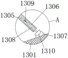
fig. 8 is an enlarged view of a portion of the invention at a in fig. 7.
In the figure: 1. a transport mechanism; 101. a driven gear; 102. a stop lever; 103. a drying table; 104. a chain; 105. a driving gear; 106. a charging chute; 107. a conveyor belt; 108. a drive shaft; 109. a reduction motor; 2. heating plates; 3. a guide plate; 4. a base; 5. a vibrating screen mechanism; 501. a sieve plate; 502. a first rotating shaft; 503. turning a handle; 504. a transmission rod; 505. a fixing plate; 506. a through groove; 507. a hinged lever; 508. a second rotating shaft; 509. a first drive motor; 6. a base; 7. a collection mechanism; 701. a material collecting box; 702. a handle; 703. a cylinder; 704. a slideway; 705. a pulley; 8. a discharging mechanism; 801. a threaded delivery shaft; 802. a discharge port; 803. a third drive motor; 804. a discharging barrel; 9. a blade; 10. a stirring shaft; 11. an exhaust fan; 12. a dust exhaust pipe; 1301. a filter screen; 1302. a dust removal net; 1303. a rotating electric machine; 1304. a drive shaft; 1341. a blanking hole; 1305. fixing the rod; 1306. a moving groove; 1307. a protrusion; 1308. a travel bar; 1309. a pressure spring; 1310. striking a ball; 13. a dust collection box; 14. a dust extraction pipe; 15. a dust extraction hood; 16. a screening box; 17. a housing; 18. a material pumping pipe; 19. a second drive motor; 20. a pipeline fan; 21. filtering the plate; 22. a material guide plate; 23. a rubber plug; 24. an electromagnetic valve.
Detailed Description
The technical solutions in the embodiments of the present invention will be clearly and completely described below with reference to the drawings in the embodiments of the present invention, and it is obvious that the described embodiments are only a part of the embodiments of the present invention, and not all of the embodiments. All other embodiments, which can be derived by a person skilled in the art from the embodiments given herein without making any creative effort, shall fall within the protection scope of the present invention.
Example 1: referring to fig. 1-6, a drying device for tea leaves comprises a base 4 and a base 6, wherein the base 6 is arranged at the bottom end of the base 4, a heating plate 2 is arranged at the top end of the base 4, the type of the heating plate 2 can be JQ-024, a conveying mechanism 1 is arranged at the top end of the heating plate 2, a guide plate 3 is arranged at one side of the top end of the base 4, a vibrating screen mechanism 5 is arranged at the middle position inside the base 4, a collecting mechanism 7 is arranged at the bottom end inside the base 4, a shell 17 is arranged at the other side of the base 4, a pipeline fan 20 is arranged between the shell 17 and the base 4, the type of the pipeline fan 20 can be HCC-30S, a material pumping pipe 18 is respectively arranged at the output end and the input end of the pipeline fan 20, the shell 17 is communicated with the inside the base 4 through the material pumping pipe 18, a discharging mechanism 8 is arranged at the bottom end inside the shell 17, and a winnowing mechanism is arranged at the top end inside the shell 17;
referring to fig. 1-6, a drying apparatus for tea further comprises an air separation mechanism, the air separation mechanism comprises a screening box 16, the screening box 16 is disposed at a middle position inside a housing 17, a stirring shaft 10 is transversely disposed inside the screening box 16, blades 9 are disposed outside the stirring shaft 10, two sides of the stirring shaft 10 penetrate through an inner wall of the screening box 16 and are movably connected with an inner wall of the housing 17, one side of the housing 17 is provided with a second driving motor 19, the type of the second driving motor 19 can be Y90S-2, an output end of the second driving motor 19 is fixedly connected with one side of the stirring shaft 10 through a coupling, the other side of the housing 17 is fixedly connected with a dust collection box 13, a filter screen 12 is disposed at a bottom end inside the dust collection box 13, an exhaust fan 11 is disposed at a bottom end of the dust collection box 13, the type of the exhaust fan 11 can be BFX-100, a dust exhaust pipe 14 is disposed at a top end of the dust collection box 13, the input end of the dust extraction pipe 14 penetrates through the side wall of the shell 17 and extends to the upper part of the screening box 16, the input end of the dust extraction pipe 14 is fixedly connected with a dust extraction cover 15, and the inside of the dust extraction cover 15 is fixedly connected with a filter plate 21;
the blades 9 are arranged in four groups outside the stirring shaft 10 and distributed in an annular mode relative to the axis of the stirring shaft 10, and a plurality of groups of circular through holes are arrayed inside the blades 9;
specifically, as shown in fig. 1, 4 and 5, the pipeline fan 20 draws out the dried and screened qualified tea leaves and sends the tea leaves into the screening box 16 through the material pumping pipe 18, the second driving motor 19 and the exhaust fan 11 are synchronously started, the stirring shaft 10 rotates to drive the blades 9 to continuously turn over the tea leaves in the screening box 16, during the tea leaf turning process, the dust hood 15 sucks away light impurities such as dust and broken particles, the filter plate 21 in the dust hood 15 can prevent the complete tea leaves with larger leaf diameter from being sucked away, the impurities enter the dust collection box 13 to be collected and then concentrated, a plurality of groups of circular through holes are arrayed inside the blades 9 and can be passed through by the tea leaves, the tea leaves are scattered during the turning and stirring, and the air separation quality is further improved.
Example 2: the transmission mechanism 1 consists of a driven gear 101, a stop lever 102, a drying platform 103, a chain 104, a driving gear 105, a charging chute 106, a conveyor belt 107, a transmission shaft 108 and a speed reduction motor 109, the drying table 103 is arranged at the top end of the base 4, a conveyor belt 107 is arranged inside the drying table 103, a driving gear 105 is arranged on one side inside the conveyor belt 107, a driven gear 101 is arranged on the other side inside the conveyor belt 107, a transmission shaft 108 is fixedly connected to the other end of the driving gear 105, a speed reduction motor 109 is fixedly connected to the other end of one side of the drying table 103, the model of the speed reduction motor 109 can be 2IK6GN-C, the output end of the speed reduction motor 109 is fixedly connected with the transmission shaft 108 through a transmission belt, a chain 104 is meshed outside the driving gear 105 and the driven gear 101, a stop lever 102 is arranged above the other side of the conveyor belt 107, a blanking groove 106 is arranged on one side of the drying table 103, and the bottom end of the blanking groove 106 is communicated with the inside of the base 4;
the chains 104 are respectively arranged at two ends of the drying platform 103 and are symmetrically distributed about the horizontal central line of the drying platform 103, and the top opening of the charging chute 106 is obliquely arranged;
specifically, as shown in fig. 1 and 2, the heating plate 2 is started to heat up and preheat, tea leaves are spread on the top of the conveying belt 107, the speed reduction motor 109 is started, the transmission shaft 108 transmits torque, the driving gear 105 and the driven gear 101 are meshed with the chain 104 to rotate, the conveying belt 107 slowly conveys the tea leaves towards the direction of the blanking groove 106, and due to the fact that the tea leaves are spread manually and uneven, the blocking rod 102 can push the tea leaves to be flat when the conveying belt 107 runs, so that the tea leaves are heated uniformly as much as possible, moisture is evaporated at a specific temperature, and the drying effect is better.
Example 3: the vibrating screen mechanism 5 is composed of a screen plate 501, a first rotating shaft 502, a rotating handle 503, a transmission rod 504, a fixing plate 505, a through groove 506, a hinge rod 507 and a second rotating shaft 508, the fixing plate 505 is fixedly connected inside the base 4, a through groove 506 is arranged inside the fixing plate 505, two sides of two ends of the fixing plate 505 are respectively hinged with a hinge rod 507, the top end of the hinge rod 507 is hinged with a sieve plate 501, one side of the fixing plate 505 is movably connected with a first rotating shaft 502, one end of the first rotating shaft 502 is fixedly connected with a rotating handle 503, one end of the rotating handle 503 is fixedly connected with a transmission rod 504, the bottom end of the other side of the sieve plate 501 is movably connected with a second rotating shaft 508, one end of the second rotating shaft 508 is movably hinged with the other side of the transmission rod 504, the other end of the first rotating shaft 502 is provided with a first driving motor 509, the type of the first driving motor 509 can be Y80M2-2, and the output end of the first driving motor 509 is fixedly connected with the axis of the first rotating shaft 502 through a coupler;
the horizontal position of the top end of one side of the sieve plate 501 is lower than the bottom end of the guide plate 3, and the inclination angle of the sieve plate 501 is 20 degrees;
specifically, as shown in fig. 1 and fig. 3, the tea leaves after being heated and dried fall from the speed reduction motor 109, and are guided into the top end of the sieve plate 501 through the guide plate 3, the first driving motor 509 is started, the first rotating shaft 502 rotates and drives the rotating handle 503 to turn over, so that one side of the driving rod 504 is pulled to make a circular motion around the axis of the first rotating shaft 502, the second rotating shaft 508 also rotates synchronously, due to the back-and-forth pulling of the driving rod 504, the sieve plate 501 hinged above the fixed plate 505 vibrates at a high speed, the tea leaves bounce at the top end of the sieve plate 501, unqualified residual leaves and final leaves are screened and fall into the collecting box 701 through the through groove 506, qualified tea leaves continuously bounce to the right side of the base 4 on the obliquely arranged sieve plate 501, and the mechanism can realize automatic classification and screening molding of the tea leaves after being dried without manual screening, and is efficient and fast.
Example 4: the collecting mechanism 7 comprises a collecting box 701, a pull handle 702, an air cylinder 703, a slide way 704 and a pulley 705, wherein the collecting box 701 is arranged at the bottom end inside the base 4, the pulleys 705 are arranged at four corners of the bottom end of the collecting box 701, the slide way 704 is arranged at the bottom end of the pulley 705, the pulley 705 is embedded inside the slide way 704 and is in sliding connection with the slide way 704, the pull handle 702 is arranged at one end of the collecting box 701, the air cylinder 703 is arranged on the inner wall at the other end of the base 4, the type of the air cylinder 703 can be SDA, and the output end of the air cylinder 703 is fixedly connected with the other end of the collecting box 701;
the length of the material collecting box 701 is larger than that of the through groove 506;
specifically, as shown in fig. 1, the collection box 701 continuously collects the fallen leaves and crushed leaves in the through groove 506, when the collection box 701 is full of tea leaves, the air cylinder 703 is started, the piston rod at the output end of the air cylinder 703 pushes the collection box 701 out of the base 4, the pulley 705 smoothly slides inside the slideway 704, and a worker can pour the tea leaves into the sorting device for further sorting and subsequent processing, or can pull out the handle 702 manually, and the automatic pushing-out and the manual pushing-out are combined, so that the operation is convenient.
Example 5: the discharging mechanism 8 is composed of a threaded conveying shaft 801, a discharging port 802, a third driving motor 803 and a discharging barrel 804, the discharging barrel 804 is fixedly connected to the bottom end inside the shell 17, the circle center of the top end of the discharging barrel 804 is fixedly connected with the third driving motor 803, the model of the third driving motor 803 can be JSS57P2N, the output end of the third driving motor 803 is fixedly connected with the discharging port 802 through a coupler, the discharging port 802 is arranged at the bottom end of the shell 17, the discharging port 802 is communicated with the bottom end of the discharging barrel 804, and the bottom end of the third driving motor 803 extends to the lower side of the discharging port 802;
the section of the discharging barrel 804 is funnel-shaped, a blanking pipeline is arranged at the bottom end of the screening box 16, and the discharging barrel 804 is arranged right below the blanking pipeline;
specifically, as shown in fig. 1 and 6, the tea leaves which are dried and then screened in two degrees and have better quality fall from the blanking pipeline of the screening box 16, if the tea leaves are directly discharged in large batches, the tea leaves are lighter in quality and easy to block the discharge hole 802 under the action of gravity, manual dredging is time-consuming and labor-consuming, a third driving motor 803 is arranged, the third driving motor 803 is started, the threaded conveying shaft 801 rotates, the tea leaves are quantitatively and orderly discharged along the spiral leaves, the problem of blocking is avoided, and discharging is more uniform and stable.
Example 6: a filter screen 1301 is arranged at the bottom end inside the dust collection box 13, a plurality of groups of dust collection screens 1302 are fixedly mounted on the upper side inside the dust collection box 13, an exhaust fan 11 is arranged at the top end of the dust collection box 13, a dust extraction pipe 14 is arranged at the bottom end of the dust collection box 13, the input end of the dust extraction pipe 14 penetrates through the side wall of the shell 17 and extends to the upper side of the screening box 16, a dust extraction cover 15 is fixedly connected to the input end of the dust extraction pipe 14, and a filter plate 21 is fixedly connected inside the dust extraction cover 15;
a rotating motor 1303 is fixedly arranged at the top of the dust collection box 13, a transmission shaft 1304 is fixedly arranged at the output end of the rotating motor 1303 penetrates through the top wall of the dust collection box 13, the bottom end of the transmission shaft 1304 penetrates through the bottom wall of the dust collection box 13 and is rotatably connected with the bottom wall, the transmission shaft 1304 is a hollow shaft, a plurality of groups of blanking holes 1341 are arranged on the outer side of the bottom of the transmission shaft 1304, the blanking hole 1341 is positioned at the upper side of the filter screen 1301, the middle parts of the upper sides of the filter screen 1301 and the dust removal screen 1302 are both fixedly provided with a bulge 1307, fixed rods 1305 are fixedly arranged on the left side and the right side of the transmission shaft 1304, one end, far away from the transmission shaft 1304, of each fixed rod 1305 is provided with a movable groove 1306, a moving rod 1308 is connected in the moving groove 1306 in a sliding way, a pressure spring 1309 is fixedly connected between one end of the moving rod 1308 and the moving groove 1306, the other end of the moving rod 1308 is fixedly provided with a striking ball 1310, and the striking ball 1310 is movably contacted with the protrusion 1307;
Specifically, as shown in fig. 7 and 8, the impurities enter the dust collection box 13 and the rotating motor 1303 is started, wherein the granular impurities fall on the upper side of the filter screen 1301 after entering the dust collection box 13, and further pass through the blanking hole 1341 on the outer side of the transmission shaft 1304 and further pass through the inside of the shaft, so that the granular impurities are collected at the bottom of the transmission shaft 1304, the granular impurities can be taken out by pulling out the rubber stopper 23, and the granular impurities are adsorbed by the sets of dust removal nets 1302 arranged on the upper side of the dust collection box 13, so that the clean air is discharged from the output end of the exhaust fan 11, which does not pollute the environment, but the dust removal nets 1302 are easily blocked after long-time dust removal, therefore, the transmission shaft 1304 is driven to rotate by the rotating motor 1303, so that the fixing rods 1305 on the shaft side of the transmission shaft 1304 synchronously rotate, when the impact ball 1310 contacts with the protrusion 1307, the impact ball 1310 drives the moving rod 1310 to move in the direction away from the protrusion 1307, and the pressure spring 1309 is in a compressed state, the filter net 1301 and the dust removal net 1302 are continuously vibrated by the continuous impact between the impact ball 1310 and the protrusion 1307 to accelerate the falling of dust impurities and particle impurities, thereby facilitating the collection.
The working principle is as follows: when the tea leaf drying machine is used, firstly, the heating plate 2 is started to heat up and preheat, tea leaves are spread on the top end of the conveying belt 107, the speed reduction motor 109 is started, the transmission shaft 108 transmits torque, the driving gear 105 and the driven gear 101 are meshed with the chain 104 to rotate, the conveying belt 107 slowly conveys the tea leaves to the blanking groove 106, and due to the fact that the uniformity of the tea leaves spread manually is inconsistent, the blocking rod 102 can push the tea leaves to be flat when the conveying belt 107 advances, so that the tea leaves are heated uniformly as much as possible, moisture is evaporated at a specific temperature, and the drying effect is better.
Then, the tea leaves dried by heating fall from the speed reducing motor 109, are guided into the top end of the sieve plate 501 through the guide plate 3, the first driving motor 509 is started, the first rotating shaft 502 rotates and drives the rotating handle 503 to turn over, so that one side of the driving rod 504 is pulled to do circular motion around the axis of the first rotating shaft 502, the second rotating shaft 508 also synchronously rotates, due to the back-and-forth pulling of the driving rod 504, the sieve plate 501 hinged above the fixed plate 505 vibrates at a high speed, the tea leaves bounce at the top end of the sieve plate 501, unqualified residual leaves and end leaves are sieved and fall into the material collecting box 701 through the through groove 506, qualified tea leaves continuously bounce to the right side of the base 4 on the obliquely arranged sieve plate 501, and the mechanism can realize automatic classification and screening molding of the whole tea leaves after drying without manual sieving, and is efficient and rapid.
Secondly, the residual and crushed tea leaves falling from the through groove 506 are continuously collected in the material collecting box 701, when the material collecting box 701 is full of tea leaves, the air cylinder 703 is started, a piston rod at the output end of the air cylinder 703 pushes the material collecting box 701 out of the base 4, the pulley 705 smoothly slides in the slide way 704, a worker pours the tea leaves into the sorting device for further sorting and subsequent processing, the worker can also manually pull out the handle 702, and automatic pushing and manual pushing are combined, so that the operation is convenient.
Thirdly, the pipeline fan 20 draws out the dried and screened qualified tea leaves and sends the tea leaves into the screening box 16 through the material drawing pipe 18, the second driving motor 19 and the exhaust fan 11 are synchronously started, the stirring shaft 10 rotates to drive the blades 9 to continuously turn the tea leaves in the screening box 16, in the process of tea leaf turning, the dust hood 15 sucks away impurities with light weight, such as dust, broken particles and the like, the filter plate 21 in the dust hood 15 can prevent complete tea leaves with large leaf diameter from being sucked away, the impurities enter the dust collection box 13 to be collected and then concentrated, a plurality of groups of circular through holes are arrayed in the blades 9 and can be used for the tea leaves to pass through, the tea leaves can be scattered conveniently during turning and stirring, and the winnowing quality is further improved.
Finally, what fell from the blanking pipeline of screening case 16 at this moment was the tealeaves that the stoving back was through the second degree screening, the quality is better, if direct big ejection of compact in batches, because of the tealeaves quality is lighter, easily block up discharge gate 802 under the action of gravity, manual mediation is wasted time and energy, consequently is provided with third driving motor 803, starts third driving motor 803, and screw thread delivery shaft 801 is rotatory, tealeaves along spiral leaf ration, orderly ejection of compact, needn't worry the problem of jam, the ejection of compact is more even, stable.
It will be evident to those skilled in the art that the invention is not limited to the details of the foregoing illustrative embodiments, and that the present invention may be embodied in other specific forms without departing from the spirit or essential attributes thereof. The present embodiments are therefore to be considered in all respects as illustrative and not restrictive, the scope of the invention being indicated by the appended claims rather than by the foregoing description, and all changes which come within the meaning and range of equivalency of the claims are therefore intended to be embraced therein. Any reference sign in a claim should not be construed as limiting the claim concerned.
Claims (10)
1. The utility model provides a drying equipment for tealeaves, includes base (4) and base (6), its characterized in that: the bottom of the base (4) is provided with a base (6), the top of the base (4) is provided with a heating plate (2), the top of the heating plate (2) is provided with a conveying mechanism (1), one side of the top of the base (4) is provided with a guide plate (3), a vibrating screen mechanism (5) is arranged at the middle position inside the base (4), the bottom inside the base (4) is provided with a collecting mechanism (7), the other side of the base (4) is provided with a shell (17),
the dust collection box (13) is fixedly connected to the other side of the shell (17), a filter screen (1301) is arranged at the bottom end inside the dust collection box (13), a plurality of groups of dust collection nets (1302) are fixedly mounted on the upper side inside the dust collection box (13), an exhaust fan (11) is arranged at the top end of the dust collection box (13), a dust extraction pipe (14) is arranged at the bottom end of the dust collection box (13), the input end of the dust extraction pipe (14) penetrates through the side wall of the shell (17) and extends to the upper side of the screening box (16), a dust extraction cover (15) is fixedly connected to the input end of the dust extraction pipe (14), and a filter plate (21) is fixedly connected to the inside of the dust extraction cover (15);
the dust collection box is characterized in that a rotating motor (1303) is fixedly mounted at the top of the dust collection box (13), the output end of the rotating motor (1303) penetrates through the top wall of the dust collection box (13) and is fixedly mounted with a transmission shaft (1304), the bottom end of the transmission shaft (1304) penetrates through the bottom wall of the dust collection box (13) and is rotatably connected with the bottom wall of the dust collection box (13), the transmission shaft (1304) is a hollow shaft, a plurality of groups of blanking holes (1341) are formed in the outer side of the bottom of the transmission shaft (1304), the blanking holes (1341) are located on the upper side of a filter screen (1301), protrusions (1307) are fixedly mounted in the middle of the upper sides of the filter screen (1301) and a dust removal screen (1302), fixing rods (1305) are fixedly mounted on the left side and the right side of the transmission shaft (1304), a moving groove (1306) is formed in one end of the fixing rod (1305) far away from the transmission shaft (1304), a moving rod (1308) is slidably connected with a moving rod (1308), a pressure spring (1309) is fixedly connected between one end of the moving rod (1308) and the moving groove (1306), the other end of the moving rod (1308) is fixedly provided with a striking ball (1310), and the striking ball (1310) is movably contacted with the bulge (1307).
2. The drying apparatus for tea leaves according to claim 1, wherein: a pipeline fan (20) is arranged between the shell (17) and the base (4), an output end and an input end of the pipeline fan (20) are respectively provided with a material pumping pipe (18), the shell (17) is communicated with the inside of the base (4) through the material pumping pipe (18), the bottom end of the inside of the shell (17) is provided with a discharging mechanism (8), and the top end of the inside of the shell (17) is provided with a winnowing mechanism;
the winnowing mechanism is including screening case (16), screening case (16) set up the intermediate position department in casing (17) inside, the inside of screening case (16) transversely is provided with stirring shaft (10), stirring shaft (10) outside is provided with blade (9), the both sides of stirring shaft (10) run through the inner wall of screening case (16) and with the inner wall swing joint of casing (17), one side of casing (17) is provided with second driving motor (19), one side fixed connection of shaft coupling and stirring shaft (10) is passed through to the output of second driving motor (19).
3. The drying apparatus for tea leaves according to claim 2, wherein: the blades (9) are arranged in four groups outside the stirring shaft (10) and are distributed in an annular mode relative to the axis of the stirring shaft (10), and multiple groups of circular through holes are arrayed inside the blades (9).
4. The drying apparatus for tea leaves according to claim 1, wherein: the conveying mechanism (1) consists of a driven gear (101), a stop lever (102), a drying table (103), a chain (104), a driving gear (105), a charging chute (106), a conveying belt (107), a transmission shaft (108) and a speed reduction motor (109), the drying table (103) is arranged at the top end of a base (4), the conveying belt (107) is arranged inside the drying table (103), the driving gear (105) is arranged on one side inside the conveying belt (107), the driven gear (101) is arranged on the other side inside the conveying belt (107), the transmission shaft (108) is fixedly connected to the other end of the driving gear (105), the speed reduction motor (109) is fixedly connected to the other end of one side of the drying table (103), the output end of the speed reduction motor (109) is fixedly connected with the transmission shaft (108) through the transmission belt, and the chain (104) is meshed with the driving gear (105) and the driven gear (101, a stop lever (102) is arranged above the other side of the conveyor belt (107), a charging chute (106) is arranged on one side of the drying table (103), and the bottom end of the charging chute (106) is communicated with the inside of the base (4).
5. The drying apparatus for tea leaves according to claim 4, wherein: the chain (104) is respectively arranged at two ends of the drying platform (103) and symmetrically distributed about the horizontal central line of the drying platform (103), and an opening at the top end of the charging chute (106) is obliquely arranged.
6. The drying apparatus for tea leaves according to claim 1, wherein: the vibrating screen mechanism (5) comprises a screen plate (501), a first rotating shaft (502), a rotating handle (503), a transmission rod (504), a fixed plate (505), a through groove (506), a hinged rod (507) and a second rotating shaft (508), wherein the fixed plate (505) is fixedly connected inside a base (4), the through groove (506) is arranged inside the fixed plate (505), the two sides of the two ends of the fixed plate (505) are respectively hinged with the hinged rod (507), the top end of the hinged rod (507) is hinged with the screen plate (501), one side of the fixed plate (505) is movably connected with the first rotating shaft (502), one end of the first rotating shaft (502) is fixedly connected with the rotating handle (503), one end of the rotating handle (503) is fixedly connected with the transmission rod (504), the bottom end of the other side of the screen plate (501) is movably connected with the second rotating shaft (508), one end of the second rotating shaft (508) is movably hinged with the other side, the other end of first pivot (502) is provided with first driving motor (509), the output of first driving motor (509) passes through the axle center fixed connection of shaft coupling and first pivot (502).
7. The drying apparatus for tea leaves according to claim 1, wherein: collect mechanism (7) and constitute by collection workbin (701), handle (702), cylinder (703), slide (704) and pulley (705), collection workbin (701) sets up the bottom in base (4) inside, four corners of collection workbin (701) bottom are provided with pulley (705), the bottom of pulley (705) is provided with slide (704), pulley (705) inlay the inside of slide (704) and with slide (704) sliding connection, the one end of collection workbin (701) is provided with handle (702), cylinder (703) set up the inner wall at base (4) other end, the output of cylinder (703) and the other end fixed connection of collection workbin (701).
8. The drying apparatus for tea leaves according to claim 7, wherein: the length of the material collecting box (701) is larger than that of the through groove (506).
9. The drying apparatus for tea leaves according to claim 1, wherein: dust collection box (13) bottom fixed mounting has stock guide (22), stock guide (22) slope sets up, and the lower one end department of stock guide (22) is equipped with dust exhaust pipe (12) with the inside intercommunication of dust collection box (13), dust exhaust pipe (12) middle part is equipped with solenoid valve (24), transmission shaft (1304) bottom joint has rubber buffer (23).
10. The drying method of tea leaves according to claim 1, wherein: firstly, the heating plate 2 is started to heat up and preheat, tea leaves are spread on the top end of the conveyor belt 107, the speed reduction motor 109 is started, the transmission shaft 108 transmits torque, the driving gear 105 and the driven gear 101 are meshed with the chain 104 to rotate, the conveyor belt 107 slowly conveys the tea leaves towards the direction of the charging chute 106, and the blocking rod 102 can push the tea leaves to be flat when the conveyor belt 107 runs due to the fact that uniformity of the artificially spread tea leaves is inconsistent; then, the tea leaves after being heated and dried fall from the speed reducing motor 109, the tea leaves are guided into the top end of the sieve plate 501 through the guide plate 3, the first driving motor 509 is started, the first rotating shaft 502 rotates and drives the rotating handle 503 to turn over, so that one side of the transmission rod 504 is pulled to do circular motion around the axis of the first rotating shaft 502, the second rotating shaft 508 also synchronously rotates, due to the back-and-forth pulling of the transmission rod 504, the sieve plate 501 hinged above the fixed plate 505 vibrates at a high speed, the tea leaves jump at the top end of the sieve plate 501, unqualified residual leaves and end leaves are sieved and fall into the material collecting box 701 through the through groove 506, qualified tea leaves continuously jump to the right side of the base 4 on the obliquely arranged sieve plate 501, and the mechanism can realize automatic classification and screening forming of the complete tea leaves after being dried without manual sieving, and is efficient and fast;
secondly, the residual and crushed tea leaves falling from the through groove 506 are continuously collected in the material collecting box 701, when the material collecting box 701 is full of tea leaves, the air cylinder 703 is started, a piston rod at the output end of the air cylinder 703 pushes the material collecting box 701 out of the base 4, the pulley 705 smoothly slides in the slide 704, and a worker pours the tea leaves into the sorting device for further sorting and subsequent processing; thirdly, the pipeline fan 20 draws out the dried and screened qualified tea leaves and sends the tea leaves into the screening box 16 through the material drawing pipe 18, the second driving motor 19 and the exhaust fan 11 are synchronously started, the stirring shaft 10 rotates to drive the blades 9 to continuously turn over the tea leaves in the screening box 16, in the process of tea leaf turning, the dust hood 15 sucks away impurities with light weight, such as dust, broken particles and the like, the filter plate 21 in the dust hood 15 can prevent the whole tea leaves with larger leaf diameter from being sucked away, the impurities enter the dust collection box 13 to be collected and then concentrated, the impurities enter the dust collection box 13 and simultaneously start the rotating motor 1303, wherein the particle impurities enter the dust collection box 13 and fall on the upper side of the filter screen 1301, and then enter the dust collection box through the blanking hole 1341 on the outer side of the transmission shaft 1304, so that the particle impurities are collected at the bottom of the transmission shaft 1304, the particle impurities can be taken out through the rubber plug 23, and the dust impurities are adsorbed by a plurality of dust collection nets 1302 arranged on the upper side of the dust collection box 13, clean air is discharged from the output end of the exhaust fan 11, no pollution is caused to the environment, but the dust removal net 1302 is easy to block after long-time dust removal, so that the rotating motor 1303 drives the transmission shaft 1304 to rotate, the fixed rod 1305 on the shaft side of the transmission shaft 1304 is enabled to synchronously rotate, when the impact ball 1310 is in contact with the protrusion 1307, the impact ball 1310 drives the movable handle 1308 to move in the direction away from the protrusion 1307, the pressure spring 1309 is in a compression state, the filter screen 1301 and the dust removal net 1302 continuously vibrate through continuous impact between the impact ball 1310 and the protrusion 1307, falling of dust impurities and particle impurities is accelerated, and collection is facilitated, and multiple groups of circular through holes are arrayed inside the blades 9 and can be used for tea leaves to pass through;
finally, what fell from the blanking pipeline of screening case 16 at this moment was the tealeaves that the stoving back was through the second degree screening, the quality is better, if direct big ejection of compact in batches, because of the tealeaves quality is lighter, easily block up discharge gate 802 under the action of gravity, manual mediation is wasted time and energy, consequently is provided with third driving motor 803, starts third driving motor 803, and screw thread delivery shaft 801 is rotatory, tealeaves along spiral leaf ration, orderly ejection of compact, needn't worry the problem of jam, the ejection of compact is more even, stable.
Priority Applications (1)
| Application Number | Priority Date | Filing Date | Title |
|---|---|---|---|
| CN202110566117.6A CN113405345A (en) | 2021-05-24 | 2021-05-24 | Drying equipment for tealeaves |
Applications Claiming Priority (1)
| Application Number | Priority Date | Filing Date | Title |
|---|---|---|---|
| CN202110566117.6A CN113405345A (en) | 2021-05-24 | 2021-05-24 | Drying equipment for tealeaves |
Publications (1)
| Publication Number | Publication Date |
|---|---|
| CN113405345A true CN113405345A (en) | 2021-09-17 |
Family
ID=77674578
Family Applications (1)
| Application Number | Title | Priority Date | Filing Date |
|---|---|---|---|
| CN202110566117.6A Withdrawn CN113405345A (en) | 2021-05-24 | 2021-05-24 | Drying equipment for tealeaves |
Country Status (1)
| Country | Link |
|---|---|
| CN (1) | CN113405345A (en) |
Cited By (3)
| Publication number | Priority date | Publication date | Assignee | Title |
|---|---|---|---|---|
| CN114558394A (en) * | 2022-03-22 | 2022-05-31 | 日照市岚山区人民医院(日照市第二人民医院) | Clinical anesthetic gas purification device that uses of department of anesthesia |
| CN114992986A (en) * | 2022-06-17 | 2022-09-02 | 吴淑玲 | Tea leaf drying machine capable of uniformly drying and efficiently sterilizing |
| CN116294486A (en) * | 2023-05-11 | 2023-06-23 | 福建顺茗道茶业有限公司 | Drying equipment is used in tealeaves processing |
-
2021
- 2021-05-24 CN CN202110566117.6A patent/CN113405345A/en not_active Withdrawn
Cited By (5)
| Publication number | Priority date | Publication date | Assignee | Title |
|---|---|---|---|---|
| CN114558394A (en) * | 2022-03-22 | 2022-05-31 | 日照市岚山区人民医院(日照市第二人民医院) | Clinical anesthetic gas purification device that uses of department of anesthesia |
| CN114558394B (en) * | 2022-03-22 | 2024-01-30 | 日照市岚山区人民医院(日照市第二人民医院) | Clinical anesthetic gas purification device that uses of department of anesthesia |
| CN114992986A (en) * | 2022-06-17 | 2022-09-02 | 吴淑玲 | Tea leaf drying machine capable of uniformly drying and efficiently sterilizing |
| CN116294486A (en) * | 2023-05-11 | 2023-06-23 | 福建顺茗道茶业有限公司 | Drying equipment is used in tealeaves processing |
| CN116294486B (en) * | 2023-05-11 | 2023-07-21 | 福建顺茗道茶业有限公司 | Drying equipment is used in tealeaves processing |
Similar Documents
| Publication | Publication Date | Title |
|---|---|---|
| CN113405345A (en) | Drying equipment for tealeaves | |
| CN109201474B (en) | Screening equipment for corn kernels | |
| CN113080477B (en) | Automatic shell breaking, peeling and kernel taking machine for Chinese chestnuts and using method thereof | |
| CN110369266A (en) | A kind of timber factory lumber bits Screening Treatment device | |
| CN115025960A (en) | Dust-proof screening equipment for grain processing and method thereof | |
| CN113439502A (en) | Peanut shelling and seed selecting device | |
| CN113154853A (en) | Drying equipment for tealeaves | |
| CN116833089B (en) | Raw material processing equipment and processing method for graphitized cathode production | |
| CN114425472B (en) | Biomass energy raw materials pulverizes sieving mechanism | |
| CN205056424U (en) | Honeysuckle sieve separator | |
| CN114178179B (en) | Annular V-shaped selection composite powder separator | |
| CN116237237A (en) | Agricultural product storage device with edulcoration function | |
| CN115845966A (en) | Rice grinding device for separating impurities by specific gravity | |
| CN115090210A (en) | Drum-type full-automatic coke mechanical ball making all-in-one machine | |
| CN209255396U (en) | A kind of electrostatic tea exclusion device | |
| CN113276309A (en) | Environment-friendly heat insulation plastic film processing device | |
| CN111804370A (en) | Grinding equipment | |
| CN215430131U (en) | Tea grade analysis system | |
| CN220677937U (en) | Automatic crushing and screening device for neodymium iron boron magnetic powder blocks | |
| CN220048914U (en) | Impurity removal screening machine | |
| CN220295219U (en) | Screening installation is used in nut food processing | |
| CN114377776B (en) | Even grinder of wheat of rejecting impurity | |
| CN218707465U (en) | Discharging device for asphalt concrete crusher | |
| CN218902689U (en) | Fallen leaf collecting device | |
| CN113369142B (en) | Screening plant is used in coal production |
Legal Events
| Date | Code | Title | Description |
|---|---|---|---|
| PB01 | Publication | ||
| PB01 | Publication | ||
| SE01 | Entry into force of request for substantive examination | ||
| SE01 | Entry into force of request for substantive examination | ||
| WW01 | Invention patent application withdrawn after publication | ||
| WW01 | Invention patent application withdrawn after publication |
Application publication date: 20210917 |