Walking hoisting robot for double-layer bolt ball net rack rod supplementing and hoisting method thereof
Technical Field
The invention belongs to the field of hoisting equipment, and particularly relates to a walking hoisting robot for a double-layer bolt ball net rack rod supplementing and a hoisting method thereof.
Background
At present, hoisting of domestic steel structures mainly comprises high-altitude splicing, integral lifting, block lifting and the like. Due to the fact that the hoisting range of the crane is limited, when the main body part of the structure is installed, hoisting operation cannot be conducted on the partial roof secondary structure part often. If the crane model is increased to meet the installation requirement of such scattered components, the installation measure cost is greatly increased, the construction cost is seriously influenced, and if the measure cost is not increased, the structure installation cannot be completed due to the limitation of the height and the structure covering surface size, and the installation and delivery of the structural components are seriously influenced.
Disclosure of Invention
The invention aims to provide a walking hoisting robot for a double-layer bolt ball net rack rod supplementing and a hoisting method thereof, so as to solve the technical problems.
Therefore, the invention provides a walking hoisting robot for a double-layer bolt ball net rack rod supplementing, which comprises:
the low-level track is connected with the net rack support on the double-layer bolt ball net rack;
the high-level rail is arranged on one side of the low-level rail in parallel, the bottom elevation of the high-level rail is higher than that of the low-level rail, the top of the high-level rail is flush with that of the low-level rail, and the high-level rail is connected with a net rack support on a double-layer bolt ball net rack;
the crane chassis is connected between the top of the high-level track and the top of the low-level track in a sliding manner;
the mechanical arm is connected to the top of the crane chassis;
and the driving and controlling mechanism is used for driving and controlling the crane chassis and the mechanical arm to move.
Preferably, the two sides of the bottom of the crane chassis are respectively connected with a leveling mechanism, the cross section of the leveling mechanism is in a pi shape and comprises a horizontal plate and side plates connected to the two sides of the bottom of the horizontal plate, rollers are connected between the side plates through bearings, and the rollers on the two sides of the crane chassis slide along the high-position track and the low-position track respectively.
Preferably, the bottom end of the side plate on one side of the crane chassis is lower than the upper flange plate of the high-position track, the inner side of the side plate is connected with an anti-overturning wheel through a bearing, the bottom end of the side plate on the other side of the crane chassis is lower than the upper flange plate of the low-position track, the inner side of the side plate is connected with the anti-overturning wheel through a bearing, and the anti-overturning wheels on the two sides of the crane chassis respectively slide along the bottom of the upper flange plate of the high-position track and the bottom of the upper flange plate of the low-position track.
Preferably, the low-level rail and the high-level rail are respectively connected with the net rack support bracket through bolts.
Preferably, the drive and control mechanism comprises:
the traveling motor and the speed reducer are arranged at the top of the crane chassis and are used for driving the crane chassis to move;
the winch is connected with the mechanical arm through a rope and used for driving the mechanical arm to move;
and the remote control mechanism is arranged in the winch and used for controlling the winch to work.
Preferably, the bottom of the mechanical arm is connected with a crane chassis through a slewing bearing.
Preferably, the low-level rail is HM244 × 175 × 7 × 11 section steel, and the high-level rail is HM150 × 150 × 7 × 10 section steel.
In addition, the invention also provides a hoisting method of the walking hoisting robot for the rod supplement of the double-layer bolt-ball net rack, which comprises the following steps:
step one, after double-layer bolt ball net racks on two sides of an axis are lifted to a proper position, assembling an installation unit of a ball four-bar on the ground;
secondly, a crane maintenance platform is used as a transfer platform, and the walking hoisting robot for rod compensation of the double-layer bolt ball net rack is arranged on the double-layer bolt ball net rack;
thirdly, connecting the low-position track and the high-position track with a net rack support on a double-layer bolt ball net rack respectively;
fourthly, mounting a leveling mechanism and a roller at the bottom of the crane chassis;
hoisting the crane chassis to the low-position track and the high-position track, wherein the overturn-preventing wheels on one side of the crane chassis slide along the bottom of the upper flange plate of the low-position track, and the overturn-preventing wheels on the other side of the crane chassis slide along the bottom of the upper flange plate of the high-position track;
sixthly, mounting the mechanical arm on the top of the crane chassis;
seventhly, the driving and controlling mechanism works to control the crane chassis to slide to a position to be constructed and control the mechanical arm to start hoisting, so that the installation work of the ball supplementing and rod supplementing rod is completed;
and step eight, after the structural member is installed, controlling the crane chassis to reversely run by the driving and controlling mechanism, dismantling the low-level rail and the high-level rail while running, and finally running to a position where the ground crane can hoist to complete dismantling work.
Preferably, in step four, the anti-overturning wheel is also arranged at the bottom of the chassis of the crane.
Compared with the prior art, the invention has the characteristics and beneficial effects that:
(1) the track comprises a low-position track and a high-position track which are respectively connected with the net rack support on the double-layer bolt ball net rack, compared with the common track, the track has better stability and strength, and the appearance characteristic of the upper flange plate is easy to clamp the crane sliding device. In addition, the position of the track can be set at will, so that the construction hoisting blind area can be hoisted and installed in all directions without dead angles, and the requirement of structural installation work of positions where a ground truck crane, a crawler crane or a tower crane cannot reach in the installation process of the high-altitude position of the roof structure can be met.
(2) According to the invention, the crane chassis is connected with the leveling mechanism, the anti-overturning wheels are connected to the inner sides of the side plates of the leveling mechanism, and the leveling mechanism and the anti-overturning wheels are utilized to ensure the stability and safety of the crane in the hoisting operation process.
(3) The walking type hoisting tool disclosed by the invention is hundreds of kilograms in total weight, is supported by four points, has small counter force of each fulcrum, can meet the requirements of construction of similar structures of various light and heavy roofs, and can cover all construction blind corners, so that the hoisting capacity of a crane can be properly reduced, the optimization of construction measure input is realized, and the economic benefit is realized.
(4) The invention can realize the unmanned operation of the crane, adopts a dynamic remote control mode to carry out the operation and the instruction transmission of the hoisting operation, realizes the command of the walking and hoisting operation by a set of remote sensing device, and finally realizes the integral installation. This lifting device can guarantee that on-the-spot rack whole promotion is accomplished the back, can normally carry out the follow-up installation of rack superstructure component, ensures going on smoothly of small-size structural installation, has practiced thrift a large amount of hoist and mount costs simultaneously.
(5) After the installation of the structural member is completed, the traveling type hoisting tool reversely runs, the rail and the accessories are removed while running, and finally the traveling type hoisting tool runs to a position where a ground crane can hoist, so that the removal work of a small crane is completed, and the construction efficiency is improved.
Drawings
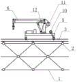
Fig. 1 is a schematic side view of a walking remote-control hoisting tool.
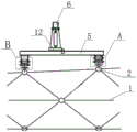
Fig. 2 is a schematic front view of a walking remote-control hoisting tool.
Fig. 3 is an enlarged view of a portion a of fig. 2.
Fig. 4 is an enlarged schematic view of part B of fig. 2.
The attached drawings are marked as follows: 1-double-layer bolt ball net rack, 2-net rack support, 3-low-position track, 4-high-position track, 5-crane chassis, 6-mechanical arm, 7-leveling mechanism, 71-horizontal plate, 72-side plate, 8-roller, 9-overturn prevention wheel, 10-walking motor and speed reducer, 11-winch and 12-slewing bearing.
Detailed Description
In order to make the technical means, innovative features, objectives and functions realized by the present invention easy to understand, the present invention is further described below.
The examples described herein are specific embodiments of the present invention, are intended to be illustrative and exemplary in nature, and are not to be construed as limiting the scope of the invention. In addition to the embodiments described herein, those skilled in the art will be able to employ other technical solutions which are obvious based on the disclosure of the claims and the specification of the present application, and these technical solutions include technical solutions which make any obvious replacement or modification for the embodiments described herein.
In the description of the present invention, it should be noted that the terms "upper", "lower", "inner", "outer", "front", "rear", "both ends", "one end", "the other end", and the like indicate orientations or positional relationships based on those shown in the drawings, and are only for convenience of description and simplicity of description, but do not indicate or imply that the referred device or element must have a specific orientation, be constructed in a specific orientation, and be operated, and thus, should not be construed as limiting the present invention. Furthermore, the terms "first" and "second" are used for descriptive purposes only and are not to be construed as indicating or implying relative importance.
In the description of the present invention, it is to be noted that, unless otherwise explicitly specified or limited, the terms "mounted," "disposed," "connected," and the like are to be construed broadly, such as "connected," which may be fixedly connected, detachably connected, or integrally connected; can be mechanically or electrically connected; they may be connected directly or indirectly through intervening media, or they may be interconnected between two elements. The specific meanings of the above terms in the present invention can be understood in specific cases to those skilled in the art.
As shown in fig. 1-4, the walking hoisting robot for rod supplement of the double-layer bolt-ball net rack comprises a low-position track 3, a high-position track 4, a crane chassis 5, a mechanical arm 6 and a driving and controlling mechanism. The low-level track 3 and the high-level track 4 can adopt I-shaped steel or H-shaped steel.
The low-level track 3 is connected with a net rack support 2 on the double-layer bolt ball net rack 1. Specifically, the low rail 3 is connected with the net rack support 2 on the double-layer bolt ball net rack 1 through bolts.
High-order track 4 parallel arrangement is in one side of low level track 3 to high-order track 4's bottom elevation is higher than low level track 3's bottom elevation, and high-order track 4's top and low level track 3's top parallel and level, high-order track 4 and the rack rest 2 on the double-deck bolt ball rack 1 are connected. Specifically, the high-level rail 4 is connected with the net rack support 2 on the double-layer bolt ball net rack 1 through bolts.
A crane chassis 5 is slidably connected between the top of the high level rail 4 and the top of the low level rail 3. The bottom two sides of the crane chassis 5 are respectively connected with a leveling mechanism 7, the cross section of the leveling mechanism 7 is in a pi shape and comprises a horizontal plate 71 and side plates 72 connected to the two sides of the bottom of the horizontal plate 71, idler wheels 8 are connected between the side plates 72 through bearings, and the idler wheels 8 on the two sides of the crane chassis 5 slide along the high-position track 4 and the low-position track 3 respectively. The bottom end of the side plate 72 on one side of the crane chassis 5 is lower than the upper flange plate of the high-position track 4, the inner side of the side plate 72 is connected with an anti-overturning wheel 9 through a bearing, the bottom end of the side plate 72 on the other side of the crane chassis 5 is lower than the upper flange plate of the low-position track 3, the inner side of the side plate 72 is connected with the anti-overturning wheel 9 through a bearing, and the anti-overturning wheels 9 on the two sides of the crane chassis 5 respectively slide along the bottom of the upper flange plate of the high-position track 4 and the bottom of the upper flange plate of the low-position track 3.
The robot arm 6 is attached to the top of the crane chassis 5. Specifically, the bottom of the robot arm 6 is connected to the crane chassis 5 through a slewing bearing 12, and the slewing bearing 12 serves as a rotation and support member for the robot arm 6.
The drive and control mechanism is used to drive and control the movement of the crane chassis 5 and the robot arm 6. The driving and controlling mechanism comprises a walking motor, a speed reducer 10, a winch 11 and a remote control mechanism. The walking motor and the speed reducer 10 are arranged at the top of the crane chassis 5 and are used for driving the crane chassis 5 to move. The winch 11 is connected with the mechanical arm 6 through a rope and is used for driving the mechanical arm 6 to move. The remote control mechanism is arranged in the winch 11 and used for controlling the winch 11 to work.
Specifically, taking a certain walking type remote control hoisting tool as an example, the low-position rail 3 is a section steel with a height of HM244 × 175 × 7 × 11, and the high-position rail 4 is a section steel with a height of HM150 × 150 × 7 × 10. The hoist 11 is an 8-ton hydraulically-driven hoist, and the designed hoisting weight is 1 ton, and the maximum actual hoisting weight is 700 kg. The length of the steel wire rope of the winch 11 is more than 60 meters, and the working radius of the crane is changed by a hydraulic telescopic component.
The hoisting method of the walking hoisting robot for the double-layer bolt ball net rack rod compensation specifically comprises the following steps:
step one, after the double-layer bolt ball net racks 1 on two sides of the axis are lifted to the right position, the installation unit of the ball four rods is assembled on the ground.
And step two, a crane maintenance platform is used as a transfer platform, and the double-layer bolt ball net rack 1 is provided with the walking hoisting robot for rod supplement.
And step three, respectively connecting the low-position rail 3 and the high-position rail 4 with a net rack support 2 on the double-layer bolt ball net rack 1. Specifically, the low-level rail 3 and the high-level rail 4 are respectively connected with the net rack support 2 on the double-layer bolt ball net rack 1 through bolts.
And step four, mounting a leveling mechanism 7 and a roller 8 at the bottom of the crane chassis 5. In order to improve the stability and safety of hoisting, an anti-overturning wheel 9 is also mounted at the bottom of the crane chassis 5. Specifically, a leveling mechanism 7 with a pi-shaped cross section is welded at the bottom of the crane chassis 5. The roller 8 is connected between the side plates 72 of the leveling mechanism 7 by means of bearings. The anti-overturning wheel 9 is then attached by bearings on the inside of the side plates 72.
And fifthly, hoisting the crane chassis 5 to the low-position rail 3 and the high-position rail 4, wherein the rollers 8 on two sides of the crane chassis 5 slide along the top of the upper flange plate of the low-position rail 3 and the top of the upper flange plate of the high-position rail 4 respectively. The anti-tip over wheels 9 on one side of the crane chassis 5 slide along the bottom of the upper flange plate of the low level rail 3 and the anti-tip over wheels 9 on the other side of the crane chassis 5 slide along the bottom of the upper flange plate of the high level rail 4.
And step six, mounting the mechanical arm 6 on the top of the crane chassis 5. Specifically, a slewing bearing 12 is installed on the top of the crane chassis 5, and the bottom of the robot arm 6 is connected to the slewing bearing 12.
And seventhly, the driving and controlling mechanism works to control the crane chassis 5 to slide to the position to be constructed and control the mechanical arm 6 to start hoisting so as to finish the installation work of the ball and rod supplementing. Specifically, the traveling motor and the speed reducer 10 drive the crane chassis 5 to move to a position to be constructed, then the remote control mechanism controls the winch 11 to work, the winch 11 drives the mechanical arm 6 to move, and the hydraulic telescopic component changes the operation radius of the mechanical arm 6.
Step eight, after the structural member is installed, the driving and control mechanism controls the crane chassis 5 to reversely run, the low-level rail 3 and the high-level rail 4 are removed while running, and finally the crane runs to a position where the ground crane can hoist, so that the removal work is completed.
The above examples are only for describing the preferred embodiments of the present invention, and are not intended to limit the scope of the present invention, and various modifications and improvements made to the technical solution of the present invention by those skilled in the art without departing from the spirit of the present invention should fall within the protection scope defined by the claims of the present invention.