CN113400473A - Rapid stirring and grouting device for tunnel slurry - Google Patents
Rapid stirring and grouting device for tunnel slurry Download PDFInfo
- Publication number
- CN113400473A CN113400473A CN202110722951.XA CN202110722951A CN113400473A CN 113400473 A CN113400473 A CN 113400473A CN 202110722951 A CN202110722951 A CN 202110722951A CN 113400473 A CN113400473 A CN 113400473A
- Authority
- CN
- China
- Prior art keywords
- shell
- casing
- arc
- rotating shaft
- cylinder
- Prior art date
- Legal status (The legal status is an assumption and is not a legal conclusion. Google has not performed a legal analysis and makes no representation as to the accuracy of the status listed.)
- Granted
Links
Images


Classifications
-
- B—PERFORMING OPERATIONS; TRANSPORTING
- B28—WORKING CEMENT, CLAY, OR STONE
- B28C—PREPARING CLAY; PRODUCING MIXTURES CONTAINING CLAY OR CEMENTITIOUS MATERIAL, e.g. PLASTER
- B28C5/00—Apparatus or methods for producing mixtures of cement with other substances, e.g. slurries, mortars, porous or fibrous compositions
- B28C5/08—Apparatus or methods for producing mixtures of cement with other substances, e.g. slurries, mortars, porous or fibrous compositions using driven mechanical means affecting the mixing
- B28C5/10—Mixing in containers not actuated to effect the mixing
- B28C5/12—Mixing in containers not actuated to effect the mixing with stirrers sweeping through the materials, e.g. with incorporated feeding or discharging means or with oscillating stirrers
- B28C5/16—Mixing in containers not actuated to effect the mixing with stirrers sweeping through the materials, e.g. with incorporated feeding or discharging means or with oscillating stirrers the stirrers having motion about a vertical or steeply inclined axis
-
- B—PERFORMING OPERATIONS; TRANSPORTING
- B28—WORKING CEMENT, CLAY, OR STONE
- B28C—PREPARING CLAY; PRODUCING MIXTURES CONTAINING CLAY OR CEMENTITIOUS MATERIAL, e.g. PLASTER
- B28C5/00—Apparatus or methods for producing mixtures of cement with other substances, e.g. slurries, mortars, porous or fibrous compositions
- B28C5/08—Apparatus or methods for producing mixtures of cement with other substances, e.g. slurries, mortars, porous or fibrous compositions using driven mechanical means affecting the mixing
- B28C5/0806—Details; Accessories
- B28C5/0856—Supporting frames or structures, e.g. supporting wheels
-
- B—PERFORMING OPERATIONS; TRANSPORTING
- B28—WORKING CEMENT, CLAY, OR STONE
- B28C—PREPARING CLAY; PRODUCING MIXTURES CONTAINING CLAY OR CEMENTITIOUS MATERIAL, e.g. PLASTER
- B28C7/00—Controlling the operation of apparatus for producing mixtures of clay or cement with other substances; Supplying or proportioning the ingredients for mixing clay or cement with other substances; Discharging the mixture
- B28C7/16—Discharge means, e.g. with intermediate storage of fresh concrete
- B28C7/162—Discharge means, e.g. with intermediate storage of fresh concrete by means of conveyors, other than those comprising skips or containers, e.g. endless belts, screws, air under pressure
-
- E—FIXED CONSTRUCTIONS
- E21—EARTH DRILLING; MINING
- E21D—SHAFTS; TUNNELS; GALLERIES; LARGE UNDERGROUND CHAMBERS
- E21D11/00—Lining tunnels, galleries or other underground cavities, e.g. large underground chambers; Linings therefor; Making such linings in situ, e.g. by assembling
- E21D11/04—Lining with building materials
- E21D11/10—Lining with building materials with concrete cast in situ; Shuttering also lost shutterings, e.g. made of blocks, of metal plates or other equipment adapted therefor
- E21D11/105—Transport or application of concrete specially adapted for the lining of tunnels or galleries ; Backfilling the space between main building element and the surrounding rock, e.g. with concrete
Abstract
The utility model provides a rapid mixing slip casting device of tunnel mud, including first casing, there is the feed inlet at the left side top of first casing, there is the hopper at the top of first casing corresponding feed inlet position, install sealed apron on the hopper, there is rabbling mechanism at the interior bottom of first casing, first pivot is connected at the top of first casing, there is first slewing mechanism on the first casing, the bottom intermediate position of first casing has first discharge gate, the first discharge gate position that corresponds of first casing has the second casing, the other installation of second casing shelters from the mechanism, the discharging pipe is connected to second casing bottom, there is first air feed mechanism on the first casing, the other installation controller of first casing. This device can last the discharge through first air feed mechanism with the mud in the first casing, and rabbling mechanism has efficient stirring function, can discharge the position that needs the slip casting with the mud in the first casing simultaneously, and the rabbling mechanism can be in the same as remaining mud in the clearance first casing simultaneously to discharge mud, can effectively prevent the waste of mud.
Description
Technical Field
The invention belongs to the field of grouting devices with stirring functions, and particularly relates to a rapid stirring grouting device for tunnel slurry.
Background
The tunnel need be through slip casting device in to appointed pipe or other position slip casting at the in-process of building, however present slip casting device stirring effect is not good, hardly stirs mud fully, and secondly general slip casting effect is not good, and intermittent outside slip casting accomplishes the back at the slip casting simultaneously, can remain not more mud in the slip casting equipment, also can cause the waste to mud.
Disclosure of Invention
The invention provides a rapid stirring and grouting device for tunnel slurry, which is used for overcoming the defects in the prior art.
The invention is realized by the following technical scheme:
a rapid stirring and grouting device for tunnel slurry comprises a first shell, wherein a feed inlet is formed in the top of the left side of the first shell, a hopper is arranged at the top of the first shell corresponding to the position of the feed inlet, a sealing cover plate is detachably arranged at the top of the hopper, a stirring mechanism is arranged at the inner bottom of the first shell, the top of the first shell is vertically and rotatably connected with a first rotating shaft, a first rotating mechanism is arranged at the top of the first shell and used for driving the first rotating shaft to rotate, the first rotating shaft is connected with the stirring mechanism, a first discharge hole is formed in the middle position of the bottom of the first shell, a second shell is arranged at the position of the first shell corresponding to the first discharge hole, a shielding mechanism is arranged beside the second shell and completely blocks the first discharge hole when the shielding mechanism is started, a discharge pipe is connected to the bottom of the second shell, and a first gas supply mechanism is arranged at the top of the first shell, the first air supply mechanism is used for supplying air into the first shell, a controller is arranged beside the first shell, and the controller is connected with the stirring mechanism, the first rotating mechanism, the shielding mechanism and the first air supply mechanism.
The rapid stirring and grouting device for tunnel slurry comprises a sliding mechanism, the sliding mechanism is arranged at the lower end of a first rotating shaft, the middle part of a fixed part of the sliding mechanism is connected with the first rotating shaft, the lower end of a movable part of the sliding mechanism is vertically provided with a waterproof electric telescopic mechanism, the bottom of the electric telescopic mechanism is provided with a third shell, the third shell is cylindrical and is arranged below the first rotating shaft, the lower end of the third shell is provided with a cylinder, the top of the cylinder is closed, the lower end of the cylinder is provided with an opening, the cylinder is vertically and rotatably connected with a second rotating shaft, the top surface of the cylinder in the third shell is provided with a second rotating mechanism, the second rotating mechanism is used for driving the second rotating shaft to rotate, the outer ring of the second rotating shaft inside the cylinder is provided with a helical blade, and the outer ring of the cylinder is provided with a plurality of first through holes in a circular array, the top of first through-hole on the drum is installed waterproof formula's third slewing mechanism, correspond first arc on the outer lane of drum and install first arc in the first through-hole position, the interior cambered surface of first arc is towards the drum, third slewing mechanism is used for driving first arc and rotates, install the gasbag on the interior cambered surface of first arc, the whole shape of first casing is the bowl form, the inboard of third casing is provided with second air feed mechanism and air exhaust mechanism, second air feed mechanism is used for supplying air in the gasbag, air exhaust mechanism is used for taking out the air in the gasbag, install the second arc on the extrados of first arc, the second arc is along the radial setting of drum, controller and slide mechanism, electronic telescopic mechanism, second slewing mechanism, third slewing mechanism, second air feed mechanism and air exhaust mechanism link to each other.
According to the rapid stirring and grouting device for tunnel slurry, the second arc-shaped plate is provided with the plurality of second through holes at equal intervals on the surface.
As above a rapid mixing slip casting device of tunnel mud, shelter from the mechanism and include the slide rail, the slide rail is transversely installed at the right side top of second casing, installs electronic slider on the slide rail, the baffle is transversely installed in the left side of electronic slider, the right side top of second casing corresponds the baffle position and has seted up the third through-hole, the baffle part stretches into in the third through-hole, correspond the baffle position on the left side inner wall of second casing and install the dog, the controller links to each other with electronic slider.
According to the rapid stirring and grouting device for tunnel slurry, the first shell is arranged on the trolley through the plurality of support rods.
According to the rapid stirring and grouting device for tunnel slurry, the protective cover is vertically arranged on the top surface of the third shell, and the movable part of the electric telescopic mechanism is arranged in the protective cover.
According to the rapid stirring and grouting device for tunnel slurry, the transverse plate is transversely installed at the inner top of the first shell, the first rotating shaft penetrates through the transverse plate, and the first rotating shaft is rotatably connected with the transverse plate.
The invention has the advantages that: the invention is controlled by the controller; the slurry in the invention is cement, when grouting is needed to an appointed position, the equipment is firstly pushed to the side of the appointed position, the discharge pipe is connected with the position needing grouting, the sealing cover plate is opened, a plurality of raw materials are added into the first shell, the sealing cover plate is locked on the hopper after the addition is completed, the stirring mechanism is started, the stirring mechanism is used for stirring the plurality of raw materials in the first shell, the first discharge hole is completely opened through the shielding mechanism after the stirring is completed, the first gas supply mechanism is started, the slurry in the first shell is discharged to the position needing grouting through the discharge pipe under the action of the first gas supply mechanism and the stirring mechanism, and meanwhile, the stirring mechanism can discharge the residual slurry in the first shell, thereby effectively preventing the waste of the slurry; the invention relates to a rapid stirring and grouting device for tunnel slurry, which has a simple structure and is convenient to use, and can continuously discharge slurry in a first shell through a first gas supply mechanism.
Drawings
In order to more clearly illustrate the embodiments of the present invention or the technical solutions in the prior art, the drawings needed to be used in the description of the embodiments or the prior art will be briefly introduced below, and it is obvious that the drawings in the following description are some embodiments of the present invention, and for those skilled in the art, other drawings can be obtained according to these drawings without creative efforts.
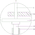
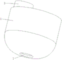
FIG. 1 is a schematic diagram of the mechanism of the present invention; FIG. 2 is a partially enlarged view of the portion I in FIG. 1; FIG. 3 is a partially enlarged view of the area II in FIG. 1; FIG. 4 is an enlarged view of a three-dimensional connection schematic of the cylinder and the first arcuate plate; FIG. 5 is a schematic three-dimensional connection of the first housing and the hopper; fig. 6 is an enlarged view of a three-dimensional view of the first arcuate plate.
Detailed Description
In order to make the objects, technical solutions and advantages of the embodiments of the present invention clearer, the technical solutions in the embodiments of the present invention will be clearly and completely described below with reference to the drawings in the embodiments of the present invention, and it is obvious that the described embodiments are some, but not all, embodiments of the present invention. All other embodiments, which can be derived by a person skilled in the art from the embodiments given herein without making any creative effort, shall fall within the protection scope of the present invention.
A rapid stirring and grouting device for tunnel slurry comprises a first shell 1, wherein a feed inlet 2 is formed in the top of the left side of the first shell 1, a hopper 3 is arranged at the top of the first shell 1 corresponding to the position of the feed inlet 2, a sealing cover plate 4 is detachably arranged at the top of the hopper 3, a stirring mechanism is arranged at the inner bottom of the first shell 1, the top of the first shell 1 is vertically and rotatably connected with a first rotating shaft 5, a first rotating mechanism 6 is arranged at the top of the first shell 1, the first rotating mechanism 6 is used for driving the first rotating shaft 5 to rotate, the first rotating shaft 5 is connected with the stirring mechanism, a first discharge outlet 7 is formed in the middle position of the bottom of the first shell 1, a second shell 8 is arranged at the position of the first shell 1 corresponding to the first discharge outlet 7, a shielding mechanism is arranged beside the second shell 8, and completely shields the first discharge outlet 7 when the shielding mechanism is started, the bottom of the second shell 8 is connected with a discharge pipe 9, the top of the first shell 1 is provided with a first gas supply mechanism 10, the first gas supply mechanism 10 is used for supplying gas into the first shell 1, a controller is arranged beside the first shell 1, and the controller is connected with the stirring mechanism, the first rotating mechanism 6, the shielding mechanism and the first gas supply mechanism 10. The invention is controlled by the controller; the mud in the invention is cement, when grouting is needed to an appointed position, the equipment is firstly pushed to the side of the appointed position, the discharge pipe 9 is connected with the position needing grouting, the sealing cover plate 4 is opened, a plurality of raw materials are added into the first shell 1, after the addition is finished, the sealing cover plate 4 is locked on the hopper 3, the stirring mechanism is started, the stirring mechanism stirs the plurality of raw materials in the first shell 1, after the stirring is finished, the first discharge hole 7 is completely opened through the shielding mechanism, the first gas supply mechanism 10 is started, under the action of the first gas supply mechanism 10 and the stirring mechanism, the mud in the first shell 1 is discharged to the position needing grouting through the discharge pipe 9, meanwhile, the stirring mechanism can discharge the residual mud in the first shell 1, and the waste of the mud is effectively prevented; the invention relates to a rapid stirring and grouting device for tunnel slurry, which has a simple structure and is convenient to use, and can continuously discharge slurry in a first shell 1 through a first gas supply mechanism 10.
Specifically, as shown in the figures, the stirring mechanism according to the embodiment includes a sliding mechanism 17, the sliding mechanism 17 is installed at the lower end of the first rotating shaft 5, the middle part of the fixed part of the sliding mechanism 17 is connected to the first rotating shaft 5, the lower end of the movable part of the sliding mechanism 17 is vertically installed with a waterproof electric telescopic mechanism 18, the bottom of the electric telescopic mechanism 18 is installed with a third housing 11, the third housing 11 is cylindrical, the third housing 11 is disposed below the first rotating shaft 5, the lower end of the third housing 11 is installed with a cylinder 12, the top of the cylinder 12 is closed, the lower end of the cylinder 12 is provided with an opening, the cylinder 12 is vertically and rotatably connected with a second rotating shaft 13, the top of the cylinder 12 in the third housing 11 is installed with a second rotating mechanism 14, the second rotating mechanism 14 is used for driving the second rotating shaft 13 to rotate, the outer ring of the second rotating shaft 13 inside the cylinder, the circular array on the outer lane of drum 12 has a plurality of first through-holes 16, the top of first through-hole 16 on drum 12 is installed with waterproof third slewing mechanism 19, first arc 20 is installed on the outer lane of drum 12 corresponding to first through-hole 16 position, the inner arc of first arc 20 faces drum 12, third slewing mechanism 19 is used for driving first arc 20 to rotate, install gasbag 21 on the inner arc of first arc 20, the whole shape of first casing 1 is bowl-shaped, the inboard of third casing 11 is provided with second air feed mechanism 22 and air exhaust mechanism 23, second air feed mechanism 22 is used for supplying air to gasbag 21, air exhaust mechanism 23 is used for exhausting air in gasbag 12, the outer arc of first arc 20 is installed with second arc 24, second arc 24 is arranged along the radial of drum 12, controller and sliding mechanism 17, electric telescopic mechanism 18, second slewing mechanism 14, controller and sliding mechanism 17, The third rotating mechanism 19, the second air supply mechanism 22 and the air exhaust mechanism 23 are connected. When the slurry needs to be stirred by the stirring mechanism, the third rotating mechanism 19 is started, the third rotating mechanism 19 drives the first arc-shaped plate 20 to rotate upwards until the first arc-shaped plate 20 is completely unfolded upwards, the first rotating mechanism 6 is started, the first rotating mechanism 6 drives the first rotating shaft 5 to rotate, the first rotating shaft 5 rotates to drive the cylinder 12, the first arc-shaped plate 20 and the second arc-shaped plate 24 to rotate, and the rotation of the first arc-shaped plate 20 and the second arc-shaped plate 24 can stir the slurry in the first shell 1; in the stirring process, the second rotating mechanism 14 can be started, the second rotating mechanism 14 drives the second rotating shaft 13 and the helical blade 15 to rotate, and the slurry in the first shell 1 can be stirred more fully through the rotating helical blade 15; in the stirring process, the second air supply mechanism 22 and the air exhaust mechanism 23 can be used for circularly supplying air and exhausting air into the air bag 21 so that the air bag 21 is expanded and contracted in a reciprocating manner, and the process can drive the slurry in the first shell 1 to move, so that the slurry in the first shell 1 is stirred more fully; meanwhile, in the stirring process, the sliding mechanism 17 and the electric telescopic mechanism 18 can be started, the sliding mechanism 17 and the electric telescopic mechanism 18 can drive the first arc-shaped plate 20 and the second arc-shaped plate 24 to move, and in the process, the slurry in the first shell 1 can be stirred more fully; after stirring is completed, when slurry in the first shell 1 needs to be discharged outwards through the discharge pipe 9, firstly, the first discharge hole 7 is completely opened through the shielding mechanism, the slurry in the first shell 1 flows into the second shell 8 through the first discharge hole 7 under the action of gravity, the first gas supply mechanism 10 is started, the first gas supply mechanism 10 continuously discharges the slurry in the first shell 1 outwards through the discharge pipe 9, in the discharging process, the second rotating mechanism 14 is started, the second rotating mechanism 14 drives the second rotating shaft 13 and the helical blade 15 to rotate, and the helical blade 15 can continuously press the slurry in the first shell 1 into the second shell 8 and discharge outwards through the discharge pipe 9 in the rotating process; meanwhile, in the process of discharging and grouting outwards, the third rotating mechanism 19 can be started, the third rotating mechanism 19 drives the first arc-shaped plate 20 to rotate upwards until the first arc-shaped plate 20 is unfolded completely upwards, the air pumping mechanism 23 is started, the air pumping mechanism 23 pumps air in the air bag 21 out, the air bag 21 is internally contracted and is connected with the inner arc surface of the first arc-shaped plate 20, the third rotating mechanism 19 is started, the third rotating mechanism 19 drives the first arc-shaped plate 20 to rotate downwards, the first arc-shaped plate 20 can stir the slurry in the first shell 8 into the cylinder 12 by means of the inner arc surface of the first arc-shaped plate 20 in the rotating process, when the first arc-shaped plate 20 rotates downwards to the limit position, the second air supply mechanism 22 is started, the second air supply mechanism 22 supplies air to the air bag 21, the air bag 21 ejects the slurry on the inner arc surface of the first arc-shaped plate 20 into the cylinder 12, and can extrude the slurry in the cylinder 12, the discharge pipe 9 can increase the discharge pressure of grouting in the grouting process, the grouting process is circulated, the slurry can be continuously stirred into the cylinder 12 through the first arc-shaped plate 20 and extruded to the cylinder 12, and meanwhile, the inner side surface of the first arc-shaped plate 20 is arc-shaped, so that the slurry in the first shell 1 can be stirred into the cylinder 12 more easily; when the mud that remains with first casing 1 is cleared up to needs, accessible control slide mechanism 17, electric telescopic handle mechanism 18 and first rotation mechanism 6 drive second arc 24 from last to down along the inner wall of first casing 1, scrape the mud that remains on the inner wall of first casing 1 totally to outwards discharge through discharging pipe 9.
Specifically, as shown in the drawings, a plurality of second through holes 25 are equidistantly formed on the surface of the second arc-shaped plate 24 according to the embodiment. The stirring mechanism can extrude the mud in the first shell 1 outwards through the second through hole 25 in the process of stirring the mud in the first shell 1, and the process can ensure that the mud in the first shell 1 can be stirred more fully.
Further, as shown in the figure, the shielding mechanism in this embodiment includes slide rail 26, slide rail 26 transversely installs at the right side top of second casing 8, installs electronic slider 27 on slide rail 26, and baffle 28 is transversely installed in the left side of electronic slider 27, and third through-hole 29 has been seted up to the corresponding baffle 28 position in right side top of second casing 8, and baffle 28 part stretches into in third through-hole 29, corresponds baffle 28 position on the left side inner wall of second casing 8 and installs dog 30, and the controller links to each other with electronic slider 27. When the first discharge port 7 needs to be completely blocked by the blocking mechanism, the electric slide block 27 is started, the electric slide block 27 drives the baffle 28 to slide leftwards until the baffle 28 completely covers the first discharge port 7, and the baffle 30 can effectively prevent the baffle 28 from being extruded by slurry in the first shell 1 to deform; when the first discharge hole 7 needs to be completely opened, the operation is reversed.
Further, as shown in the drawings, the first casing 1 of the present embodiment is mounted on a cart 32 through a plurality of support rods 31. The user is facilitated to move the apparatus by means of the cart 32.
Further, as shown in the drawings, a protection cover 33 is vertically installed on the top surface of the third housing 11 according to the embodiment, and the movable portion of the electric telescopic mechanism 18 is disposed in the protection cover 33. The protective cover 33 can effectively prevent the slurry in the first housing 1 from adhering to the movable outer ring of the electric telescopic mechanism 18, which causes the electric telescopic mechanism 18 not to be normally telescopic.
Furthermore, as shown in the drawings, a transverse plate 34 is transversely installed at the inner top of the first casing 1, the first rotating shaft 5 penetrates through the transverse plate 34, and the first rotating shaft 5 and the transverse plate 34 are rotatably connected. The transverse plate 34 can effectively prevent the first rotating shaft 5 from shaking violently to cause bending deformation of the first rotating shaft 5 in the rotating process of the first rotating shaft 5.
Finally, it should be noted that: the above examples are only intended to illustrate the technical solution of the present invention, but not to limit it; although the present invention has been described in detail with reference to the foregoing embodiments, it will be understood by those of ordinary skill in the art that: the technical solutions described in the foregoing embodiments may still be modified, or some technical features may be equivalently replaced; and such modifications or substitutions do not depart from the spirit and scope of the corresponding technical solutions of the embodiments of the present invention.
Claims (7)
1. The utility model provides a rapid mixing slip casting device of tunnel mud which characterized in that: comprises a first shell (1), a feed inlet (2) is arranged at the top of the left side of the first shell (1), a hopper (3) is arranged at the top of the first shell (1) corresponding to the feed inlet (2), a sealing cover plate (4) is detachably arranged at the top of the hopper (3), a stirring mechanism is arranged at the inner bottom of the first shell (1), the top of the first shell (1) is vertically and rotatably connected with a first rotating shaft (5), a first rotating mechanism (6) is arranged at the top of the first shell (1), the first rotating mechanism (6) is used for driving the first rotating shaft (5) to rotate, the first rotating shaft (5) is connected with the stirring mechanism, a first discharge outlet (7) is arranged at the middle position of the bottom of the first shell (1), a second shell (8) is arranged at the position of the first shell (1) corresponding to the first discharge outlet (7), and a shielding mechanism is arranged beside the second shell (8), shelter from the mechanism and block first discharge gate (7) completely at the beginning, second casing (8) bottom is connected with discharging pipe (9), first air feed mechanism (10) are installed at the top of first casing (1), first air feed mechanism (10) are used for to first casing (1) internal gas supply, the other controller of installing of first casing (1), the controller links to each other with rabbling mechanism, first slewing mechanism (6), shelter from mechanism, first air feed mechanism (10).
2. The rapid stirring grouting device for tunnel slurry according to claim 1, characterized in that: the stirring mechanism comprises a sliding mechanism (17), the sliding mechanism (17) is installed at the lower end of a first rotating shaft (5), the middle part of a fixed part of the sliding mechanism (17) is connected with the first rotating shaft (5), a waterproof electric telescopic mechanism (18) is vertically installed at the lower end of a movable part of the sliding mechanism (17), a third shell (11) is installed at the bottom of the electric telescopic mechanism (18), the third shell (11) is cylindrical, the third shell (11) is arranged below the first rotating shaft (5), a cylinder (12) is installed at the lower end of the third shell (11), the top of the cylinder (12) is closed, the lower end of the cylinder (12) is provided with an opening, a second rotating shaft (13) is vertically and rotatably connected onto the cylinder (12), a second rotating mechanism (14) is installed on the top surface of the cylinder (12) in the third shell (11), and the second rotating mechanism (14) is used for driving the second rotating shaft (13) to rotate, the outer ring of a second rotating shaft (13) on the inner side of a cylinder (12) is provided with a helical blade (15), the outer ring of the cylinder (12) is provided with a plurality of first through holes (16) in a circular array manner, the top of the first through holes (16) on the cylinder (12) is provided with a waterproof third rotating mechanism (19), the outer ring of the cylinder (12) is provided with a first arc-shaped plate (20) corresponding to the first through holes (16), the inner arc surface of the first arc-shaped plate (20) faces the cylinder (12), the third rotating mechanism (19) is used for driving the first arc-shaped plate (20) to rotate, the inner arc surface of the first arc-shaped plate (20) is provided with an air bag (21), the first shell (1) is bowl-shaped as a whole, the inner side of a third shell (11) is provided with a second air supply mechanism (22) and an air exhaust mechanism (23), the second air supply mechanism (22) is used for supplying air to the air bag (21), and the air exhaust mechanism (23) is used for exhausting air in the air bag (12), a second arc-shaped plate (24) is installed on the outer arc surface of the first arc-shaped plate (20), the second arc-shaped plate (24) is arranged along the radial direction of the cylinder (12), and the controller is connected with the sliding mechanism (17), the electric telescopic mechanism (18), the second rotating mechanism (14), the third rotating mechanism (19), the second air supply mechanism (22) and the air exhaust mechanism (23).
3. The rapid stirring grouting device for tunnel slurry according to claim 2, characterized in that: a plurality of second through holes (25) are arranged on the surface of the second arc-shaped plate (24) at equal intervals.
4. The rapid stirring grouting device for tunnel slurry according to claim 1 or 2, characterized in that: the shielding mechanism comprises a sliding rail (26), the sliding rail (26) is transversely installed at the top of the right side of the second shell (8), an electric sliding block (27) is installed on the sliding rail (26), a baffle (28) is transversely installed on the left side of the electric sliding block (27), a third through hole (29) is formed in the position, corresponding to the baffle (28), of the top of the right side of the second shell (8), the baffle (28) partially extends into the third through hole (29), a stop block (30) is installed on the inner wall of the left side of the second shell (8) and corresponds to the position of the baffle (28), and the controller is connected with the electric sliding block (27).
5. The rapid stirring grouting device for tunnel slurry according to claim 1 or 2, characterized in that: the first shell (1) is arranged on a trolley (32) through a plurality of support rods (31).
6. The rapid stirring grouting device for tunnel slurry according to claim 2, characterized in that: the top surface of the third shell (11) is vertically provided with a protective cover (33), and the movable part of the electric telescopic mechanism (18) is arranged in the protective cover (33).
7. The rapid stirring grouting device for tunnel slurry according to claim 1 or 2, characterized in that: the inner top of the first shell (1) is transversely provided with a transverse plate (34), the first rotating shaft (5) penetrates through the transverse plate (34), and the first rotating shaft (5) is rotatably connected with the transverse plate (34).
Priority Applications (1)
| Application Number | Priority Date | Filing Date | Title |
|---|---|---|---|
| CN202110722951.XA CN113400473B (en) | 2021-06-29 | 2021-06-29 | Rapid stirring and grouting device for tunnel slurry |
Applications Claiming Priority (1)
| Application Number | Priority Date | Filing Date | Title |
|---|---|---|---|
| CN202110722951.XA CN113400473B (en) | 2021-06-29 | 2021-06-29 | Rapid stirring and grouting device for tunnel slurry |
Publications (2)
| Publication Number | Publication Date |
|---|---|
| CN113400473A true CN113400473A (en) | 2021-09-17 |
| CN113400473B CN113400473B (en) | 2022-10-21 |
Family
ID=77679933
Family Applications (1)
| Application Number | Title | Priority Date | Filing Date |
|---|---|---|---|
| CN202110722951.XA Active CN113400473B (en) | 2021-06-29 | 2021-06-29 | Rapid stirring and grouting device for tunnel slurry |
Country Status (1)
| Country | Link |
|---|---|
| CN (1) | CN113400473B (en) |
Citations (31)
| Publication number | Priority date | Publication date | Assignee | Title |
|---|---|---|---|---|
| SU1169826A1 (en) * | 1983-12-21 | 1985-07-30 | Восточный научно-исследовательский горнорудный институт | Method of mixing loose materials in sealed hopper |
| JPH11294094A (en) * | 1998-04-07 | 1999-10-26 | Mitsui Constr Co Ltd | Lining device for tunnel |
| JP2003103510A (en) * | 2001-09-28 | 2003-04-09 | Oru Japan Kk | Apparatus for cleaning of concrete extraneous matter |
| CN201841602U (en) * | 2010-08-09 | 2011-05-25 | 鲍威 | Concrete pressure blender |
| CN103291323A (en) * | 2013-05-24 | 2013-09-11 | 山东鲁科自动化技术有限公司 | Wet-type concrete spray unit |
| CN204622319U (en) * | 2015-02-12 | 2015-09-09 | 天津炬实科技发展有限公司 | A kind of concrete pouring device |
| CN206274006U (en) * | 2016-12-21 | 2017-06-23 | 王铭浩 | A kind of tunnel catheter grouting device |
| CN107386652A (en) * | 2017-09-19 | 2017-11-24 | 芜湖金智王机械设备有限公司 | Concreting car |
| CN207470198U (en) * | 2017-09-14 | 2018-06-08 | 吴波 | A kind of constructing tunnel slip casting machine of anti-clogging mortar leakage prevention |
| CN108374419A (en) * | 2018-02-11 | 2018-08-07 | 温州燧人智能科技有限公司 | A kind of pulp shooting machine |
| CN109157852A (en) * | 2018-09-26 | 2019-01-08 | 褚成亮 | A kind of organosilicon slag slurry processing unit |
| CN109183585A (en) * | 2018-09-03 | 2019-01-11 | 刘大康 | A kind of expressway surface repair apparatus |
| CN109366738A (en) * | 2018-10-23 | 2019-02-22 | 金彬 | A kind of building building cement rapid mixer technique |
| CN208542284U (en) * | 2018-06-26 | 2019-02-26 | 重庆水利电力职业技术学院 | A kind of constructing tunnel ore reduction device |
| CN111058449A (en) * | 2019-12-31 | 2020-04-24 | 郑州维霖工程科技有限公司 | Portable grouting device and grouting vehicle |
| CN210414986U (en) * | 2019-05-11 | 2020-04-28 | 嘉兴市本正建设有限公司 | Dry powder mortar agitated vessel |
| CN210598995U (en) * | 2019-05-10 | 2020-05-22 | 中铁二十二局集团第五工程有限公司 | Grouting device for measuring cavity in tunnel |
| CN211306791U (en) * | 2019-12-17 | 2020-08-21 | 江西省科森建筑科技有限公司 | Grouting device is used in production of cement concrete prefabricated component |
| CN111997650A (en) * | 2019-05-26 | 2020-11-27 | 江苏锡沂高新区科技发展有限公司 | A grouting device for high-efficient slip casting in mine tunnel |
| CN112044326A (en) * | 2020-08-25 | 2020-12-08 | 高梦竹 | Foaming machine |
| CN112318709A (en) * | 2020-10-20 | 2021-02-05 | 张俭 | Cement paste processing apparatus of row material of automatic material loading convenient to remove |
| CN112339115A (en) * | 2020-10-15 | 2021-02-09 | 株洲市东亨科技有限责任公司 | Cement stirring and grouting device capable of continuously supplying slurry |
| CN212508335U (en) * | 2020-03-24 | 2021-02-09 | 马小春 | Grouting machine for tunnel construction convenient to use |
| CN212583710U (en) * | 2020-05-27 | 2021-02-23 | 苑泽斌 | Grouting machine for tunnel construction |
| CN112388826A (en) * | 2020-11-08 | 2021-02-23 | 严云宵 | High-efficient stirring collection device of cement |
| CN212898530U (en) * | 2020-08-27 | 2021-04-06 | 中铁北京工程局集团有限公司 | Tunnel construction slip casting machine |
| CN112706295A (en) * | 2020-12-28 | 2021-04-27 | 南京茆玺电子商务有限公司 | Building concrete mixer |
| CN213203807U (en) * | 2020-06-16 | 2021-05-14 | 中交投资项目管理有限公司 | Grouting device for tunnel and bridge construction |
| CN112936596A (en) * | 2021-02-01 | 2021-06-11 | 诸暨市鸿畴智能科技有限公司 | Mixing arrangement is used in building material processing |
| CN112979229A (en) * | 2021-05-12 | 2021-06-18 | 李思颖 | C35 underwater concrete and preparation method thereof |
| CN113829502A (en) * | 2021-08-23 | 2021-12-24 | 鲜孝刚 | Agitated vessel for cement manufacture |
-
2021
- 2021-06-29 CN CN202110722951.XA patent/CN113400473B/en active Active
Patent Citations (31)
| Publication number | Priority date | Publication date | Assignee | Title |
|---|---|---|---|---|
| SU1169826A1 (en) * | 1983-12-21 | 1985-07-30 | Восточный научно-исследовательский горнорудный институт | Method of mixing loose materials in sealed hopper |
| JPH11294094A (en) * | 1998-04-07 | 1999-10-26 | Mitsui Constr Co Ltd | Lining device for tunnel |
| JP2003103510A (en) * | 2001-09-28 | 2003-04-09 | Oru Japan Kk | Apparatus for cleaning of concrete extraneous matter |
| CN201841602U (en) * | 2010-08-09 | 2011-05-25 | 鲍威 | Concrete pressure blender |
| CN103291323A (en) * | 2013-05-24 | 2013-09-11 | 山东鲁科自动化技术有限公司 | Wet-type concrete spray unit |
| CN204622319U (en) * | 2015-02-12 | 2015-09-09 | 天津炬实科技发展有限公司 | A kind of concrete pouring device |
| CN206274006U (en) * | 2016-12-21 | 2017-06-23 | 王铭浩 | A kind of tunnel catheter grouting device |
| CN207470198U (en) * | 2017-09-14 | 2018-06-08 | 吴波 | A kind of constructing tunnel slip casting machine of anti-clogging mortar leakage prevention |
| CN107386652A (en) * | 2017-09-19 | 2017-11-24 | 芜湖金智王机械设备有限公司 | Concreting car |
| CN108374419A (en) * | 2018-02-11 | 2018-08-07 | 温州燧人智能科技有限公司 | A kind of pulp shooting machine |
| CN208542284U (en) * | 2018-06-26 | 2019-02-26 | 重庆水利电力职业技术学院 | A kind of constructing tunnel ore reduction device |
| CN109183585A (en) * | 2018-09-03 | 2019-01-11 | 刘大康 | A kind of expressway surface repair apparatus |
| CN109157852A (en) * | 2018-09-26 | 2019-01-08 | 褚成亮 | A kind of organosilicon slag slurry processing unit |
| CN109366738A (en) * | 2018-10-23 | 2019-02-22 | 金彬 | A kind of building building cement rapid mixer technique |
| CN210598995U (en) * | 2019-05-10 | 2020-05-22 | 中铁二十二局集团第五工程有限公司 | Grouting device for measuring cavity in tunnel |
| CN210414986U (en) * | 2019-05-11 | 2020-04-28 | 嘉兴市本正建设有限公司 | Dry powder mortar agitated vessel |
| CN111997650A (en) * | 2019-05-26 | 2020-11-27 | 江苏锡沂高新区科技发展有限公司 | A grouting device for high-efficient slip casting in mine tunnel |
| CN211306791U (en) * | 2019-12-17 | 2020-08-21 | 江西省科森建筑科技有限公司 | Grouting device is used in production of cement concrete prefabricated component |
| CN111058449A (en) * | 2019-12-31 | 2020-04-24 | 郑州维霖工程科技有限公司 | Portable grouting device and grouting vehicle |
| CN212508335U (en) * | 2020-03-24 | 2021-02-09 | 马小春 | Grouting machine for tunnel construction convenient to use |
| CN212583710U (en) * | 2020-05-27 | 2021-02-23 | 苑泽斌 | Grouting machine for tunnel construction |
| CN213203807U (en) * | 2020-06-16 | 2021-05-14 | 中交投资项目管理有限公司 | Grouting device for tunnel and bridge construction |
| CN112044326A (en) * | 2020-08-25 | 2020-12-08 | 高梦竹 | Foaming machine |
| CN212898530U (en) * | 2020-08-27 | 2021-04-06 | 中铁北京工程局集团有限公司 | Tunnel construction slip casting machine |
| CN112339115A (en) * | 2020-10-15 | 2021-02-09 | 株洲市东亨科技有限责任公司 | Cement stirring and grouting device capable of continuously supplying slurry |
| CN112318709A (en) * | 2020-10-20 | 2021-02-05 | 张俭 | Cement paste processing apparatus of row material of automatic material loading convenient to remove |
| CN112388826A (en) * | 2020-11-08 | 2021-02-23 | 严云宵 | High-efficient stirring collection device of cement |
| CN112706295A (en) * | 2020-12-28 | 2021-04-27 | 南京茆玺电子商务有限公司 | Building concrete mixer |
| CN112936596A (en) * | 2021-02-01 | 2021-06-11 | 诸暨市鸿畴智能科技有限公司 | Mixing arrangement is used in building material processing |
| CN112979229A (en) * | 2021-05-12 | 2021-06-18 | 李思颖 | C35 underwater concrete and preparation method thereof |
| CN113829502A (en) * | 2021-08-23 | 2021-12-24 | 鲜孝刚 | Agitated vessel for cement manufacture |
Also Published As
| Publication number | Publication date |
|---|---|
| CN113400473B (en) | 2022-10-21 |
Similar Documents
| Publication | Publication Date | Title |
|---|---|---|
| CN104826538B (en) | For the automation integrated equipment of paint production | |
| CN109227949B (en) | Cement paste stirring and mixing device | |
| CN218058758U (en) | Sludge uniform solidification device | |
| CN113400473B (en) | Rapid stirring and grouting device for tunnel slurry | |
| CN210883979U (en) | Dry powder mortar hoisting device | |
| CN107344393A (en) | A kind of cement mixer | |
| CN218485728U (en) | Building engineering construction is with mixing agitated vessel | |
| CN205521929U (en) | Rotation is added water in advance and is stirred mortar basin | |
| CN112518992A (en) | Feeding equipment for cement processing | |
| CN212602609U (en) | Powder agitated vessel for construction | |
| CN212236179U (en) | Energy-saving stirring machine | |
| CN210282748U (en) | Planetary mixer for brickmaking | |
| CN210356220U (en) | Waste ink processing apparatus | |
| CN216334217U (en) | Charging devices for cement manufacture | |
| JP2001098579A (en) | Mud solidifying treatment device | |
| CN220548462U (en) | Mine grouting feeding stirring device | |
| CN210905796U (en) | Mixed material stirring device | |
| CN212399951U (en) | Cement mixing device for oil drilling and production well cementation | |
| CN217594516U (en) | Material feeding unit is used in epoxy mortar cooperation | |
| CN217016270U (en) | Mixing equipment with filtering device for preparing ink | |
| CN219482391U (en) | Powder coating processing compounding device | |
| CN218314354U (en) | Water conservancy construction cementer | |
| CN210521920U (en) | Suction filtration device of easily arranging material | |
| CN211384614U (en) | Powdery building material rapid mixing device | |
| CN217614890U (en) | Wheat is bran beating device for powder process |
Legal Events
| Date | Code | Title | Description |
|---|---|---|---|
| PB01 | Publication | ||
| PB01 | Publication | ||
| SE01 | Entry into force of request for substantive examination | ||
| SE01 | Entry into force of request for substantive examination | ||
| GR01 | Patent grant | ||
| GR01 | Patent grant |