CN113399357A - Energy-concerving and environment-protective earth cleaning equipment for earthworm production - Google Patents
Energy-concerving and environment-protective earth cleaning equipment for earthworm production Download PDFInfo
- Publication number
- CN113399357A CN113399357A CN202110769670.XA CN202110769670A CN113399357A CN 113399357 A CN113399357 A CN 113399357A CN 202110769670 A CN202110769670 A CN 202110769670A CN 113399357 A CN113399357 A CN 113399357A
- Authority
- CN
- China
- Prior art keywords
- supporting
- sliding
- rod
- blocks
- sides
- Prior art date
- Legal status (The legal status is an assumption and is not a legal conclusion. Google has not performed a legal analysis and makes no representation as to the accuracy of the status listed.)
- Withdrawn
Links
- 238000004140 cleaning Methods 0.000 title claims abstract description 34
- 241000361919 Metaphire sieboldi Species 0.000 title claims abstract description 26
- 238000004519 manufacturing process Methods 0.000 title claims abstract description 15
- XLYOFNOQVPJJNP-UHFFFAOYSA-N water Substances O XLYOFNOQVPJJNP-UHFFFAOYSA-N 0.000 claims abstract description 52
- 238000003860 storage Methods 0.000 claims abstract description 29
- 238000011010 flushing procedure Methods 0.000 claims abstract description 8
- 238000003825 pressing Methods 0.000 claims description 47
- 239000007921 spray Substances 0.000 claims description 20
- 230000005540 biological transmission Effects 0.000 claims description 10
- 239000002689 soil Substances 0.000 claims description 9
- 241001233061 earthworms Species 0.000 claims description 7
- 230000000694 effects Effects 0.000 abstract description 6
- 239000011435 rock Substances 0.000 abstract description 3
- 230000009286 beneficial effect Effects 0.000 abstract 1
- 230000009471 action Effects 0.000 description 8
- 238000010586 diagram Methods 0.000 description 7
- 238000007790 scraping Methods 0.000 description 6
- 238000005406 washing Methods 0.000 description 6
- 239000012535 impurity Substances 0.000 description 3
- 230000007547 defect Effects 0.000 description 2
- 239000003814 drug Substances 0.000 description 2
- 230000007306 turnover Effects 0.000 description 2
- 102000029816 Collagenase Human genes 0.000 description 1
- 108060005980 Collagenase Proteins 0.000 description 1
- 108010088842 Fibrinolysin Proteins 0.000 description 1
- 230000002146 bilateral effect Effects 0.000 description 1
- 229960002424 collagenase Drugs 0.000 description 1
- 239000012141 concentrate Substances 0.000 description 1
- 230000036541 health Effects 0.000 description 1
- 108010070324 lumbrokinase Proteins 0.000 description 1
- 239000000463 material Substances 0.000 description 1
- 230000004048 modification Effects 0.000 description 1
- 238000012986 modification Methods 0.000 description 1
- 102000039446 nucleic acids Human genes 0.000 description 1
- 108020004707 nucleic acids Proteins 0.000 description 1
- 150000007523 nucleic acids Chemical class 0.000 description 1
- 229940012957 plasmin Drugs 0.000 description 1
- 108090000623 proteins and genes Proteins 0.000 description 1
- 102000004169 proteins and genes Human genes 0.000 description 1
- 238000005507 spraying Methods 0.000 description 1
- 238000006467 substitution reaction Methods 0.000 description 1
- 235000013619 trace mineral Nutrition 0.000 description 1
- 239000011573 trace mineral Substances 0.000 description 1
Images


Classifications
-
- B—PERFORMING OPERATIONS; TRANSPORTING
- B08—CLEANING
- B08B—CLEANING IN GENERAL; PREVENTION OF FOULING IN GENERAL
- B08B3/00—Cleaning by methods involving the use or presence of liquid or steam
- B08B3/02—Cleaning by the force of jets or sprays
- B08B3/022—Cleaning travelling work
-
- B—PERFORMING OPERATIONS; TRANSPORTING
- B01—PHYSICAL OR CHEMICAL PROCESSES OR APPARATUS IN GENERAL
- B01D—SEPARATION
- B01D29/00—Filters with filtering elements stationary during filtration, e.g. pressure or suction filters, not covered by groups B01D24/00 - B01D27/00; Filtering elements therefor
- B01D29/01—Filters with filtering elements stationary during filtration, e.g. pressure or suction filters, not covered by groups B01D24/00 - B01D27/00; Filtering elements therefor with flat filtering elements
-
- B—PERFORMING OPERATIONS; TRANSPORTING
- B01—PHYSICAL OR CHEMICAL PROCESSES OR APPARATUS IN GENERAL
- B01D—SEPARATION
- B01D29/00—Filters with filtering elements stationary during filtration, e.g. pressure or suction filters, not covered by groups B01D24/00 - B01D27/00; Filtering elements therefor
- B01D29/62—Regenerating the filter material in the filter
- B01D29/64—Regenerating the filter material in the filter by scrapers, brushes, nozzles, or the like, acting on the cake side of the filtering element
- B01D29/6469—Regenerating the filter material in the filter by scrapers, brushes, nozzles, or the like, acting on the cake side of the filtering element scrapers
- B01D29/6484—Regenerating the filter material in the filter by scrapers, brushes, nozzles, or the like, acting on the cake side of the filtering element scrapers with a translatory movement with respect to the filtering element
-
- B—PERFORMING OPERATIONS; TRANSPORTING
- B08—CLEANING
- B08B—CLEANING IN GENERAL; PREVENTION OF FOULING IN GENERAL
- B08B13/00—Accessories or details of general applicability for machines or apparatus for cleaning
-
- B—PERFORMING OPERATIONS; TRANSPORTING
- B08—CLEANING
- B08B—CLEANING IN GENERAL; PREVENTION OF FOULING IN GENERAL
- B08B3/00—Cleaning by methods involving the use or presence of liquid or steam
- B08B3/04—Cleaning involving contact with liquid
- B08B3/044—Cleaning involving contact with liquid using agitated containers in which the liquid and articles or material are placed
-
- B—PERFORMING OPERATIONS; TRANSPORTING
- B08—CLEANING
- B08B—CLEANING IN GENERAL; PREVENTION OF FOULING IN GENERAL
- B08B3/00—Cleaning by methods involving the use or presence of liquid or steam
- B08B3/04—Cleaning involving contact with liquid
- B08B3/10—Cleaning involving contact with liquid with additional treatment of the liquid or of the object being cleaned, e.g. by heat, by electricity or by vibration
- B08B3/14—Removing waste, e.g. labels, from cleaning liquid; Regenerating cleaning liquids
Landscapes
- Chemical & Material Sciences (AREA)
- Chemical Kinetics & Catalysis (AREA)
- Cleaning By Liquid Or Steam (AREA)
Abstract
The invention discloses an energy-saving and environment-friendly earth cleaning device for earthworm production, which comprises: a base; the base is provided with a swinging component; the base is provided with a driving component; the middle part of the base is provided with a water storage component; the flushing component is arranged on the water storage component. The invention has the beneficial effects that: under the effect of rocking the subassembly, people place the earthworm in wasing the frame, pour into water into water storage frame, people step on the footboard downwards, the footboard can drive the slide bar and move down, the slide bar can drive ratchet bar and move down, when ratchet bar and ratchet contact, can drive ratchet rotation, the ratchet can drive first drive wheel and first belt and bevel gear and carousel and rotate, can drive the ejector pad when the carousel rotates and control, place the frame and wash the frame and remove about, thereby rock the earthworm, make the earth on its surface shaken off.
Description
Technical Field
The invention relates to cleaning equipment, in particular to energy-saving and environment-friendly earth cleaning equipment for earthworm production.
Background
Earthworm is one of the important Chinese medicinal materials, earthworm protein is extracted from earthworm, contains collagenase, plasmin, lumbrokinase, nucleic acid, trace elements and other components, and is widely used in medicine.
Because the earthworm grows in the soil, its surface can be infected with impurity such as a lot of earth, before the earthworm carries out the work of going into medicine on next step, for clean and health, people generally can wash its surface, people are when manual washing earthworm, can cause the cleaning unclean, and the circumstances such as drop or omit appear, it is also comparatively inconvenient to clear up, if the earthworm ware quantity that needs to clear up is more, the abluent work load is too big one by one, and concentrate to wash and lead to the earthworm damaged easily again, also can cause the condition that wastes time and energy, and the appearance operation is inconvenient, people's work efficiency is low, and intensity of labour is bigger.
Therefore, it is particularly necessary to design an energy-saving and environment-friendly earth cleaning device for earthworm production, which can automatically clean earth, has good cleaning effect and is convenient to operate, so that troubles and dangers possibly caused by most manual operations can be eliminated, and the working efficiency can be improved to solve the defects.
Disclosure of Invention
Aiming at the defects of the prior art, the invention provides energy-saving and environment-friendly earth cleaning equipment for earthworm production, which comprises: a base; the base is provided with a swinging component; the base is provided with a driving component; the middle part of the base is provided with a water storage component; the flushing component is arranged on the water storage component.
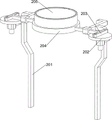
As a further preferable mode, the shaking assembly includes: the first support frame is symmetrically arranged on one side of the base; the rotary tables are rotatably arranged on one side of the upper part of the first support frame; the upper parts of the first support frames are provided with push blocks in a sliding manner, and the push blocks are respectively matched with the rotary disc in a sliding manner; a placing frame is arranged between the pushing blocks; the cleaning frame is arranged on the top of the placing frame.
As a further preferable aspect, the driving assembly includes: the first guide rod is symmetrically arranged on one side of the base; the sliding rod is arranged between the upper parts of the first guide rods in a sliding manner; the first springs are connected between the two sides of the sliding rod and the base and are respectively sleeved on the first guide rods; the middle part of one side of the sliding rod is provided with a pedal; the guide block is symmetrically arranged on one side of the base and is in sliding fit with the sliding rod; the ratchet bar is symmetrically arranged on one side of the upper part of the sliding rod in a sliding manner; the second springs are symmetrically connected between the ratchet bar and the slide bar and are respectively sleeved on the ratchet bar; the rotating shaft is rotatably arranged between the upper parts of the first supporting frames; the ratchet wheels are arranged on two sides of the rotating shaft, and the ratchet wheels on the same side are respectively matched with the ratchet bars; the outer sides of the upper parts of the first support frames are provided with first support blocks; the outer sides of the first supporting blocks are respectively rotatably provided with a bevel gear, the bottoms of the turntables are respectively provided with a bevel gear, and the bevel gears on the same side are mutually meshed; the inner sides of the lower bevel gears are provided with first driving wheels, and two sides of the rotating shaft are provided with first driving wheels; first belts are wound between the first driving wheels on the same side.
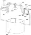
As a further preferable aspect, the water storage unit includes: the two sides of the upper middle part of the base are provided with first supporting rods; the placing table is arranged between the upper parts of the first supporting rods; the top of the placing table is provided with a water storage frame; the filter screen is arranged on the upper side of the water storage frame.
As a further preferred aspect, the flushing assembly comprises: the top of each first support frame is provided with a second support frame; the second support frame is provided with a piston cylinder; the piston cylinders are both provided with first pistons in a sliding manner; the lower sides of the outer parts of the piston cylinders are respectively provided with a first check valve; the water inlet pipe is connected between the first one-way valve and the water storage frame; the inner sides of the lower parts of the piston cylinders are provided with second check valves; the spray head is rotatably arranged between the upper parts of the second support frames; and water outlet pipes are connected between the spray head and the second one-way valve.
As a further preferable scheme, the device further comprises a pressing component, and the pressing component comprises: the outer sides of the upper parts of the first support frames are provided with second support blocks; the outer sides of the second supporting blocks are provided with pressure rods in a sliding manner, and the pressure rods are matched with the slide rods; the third springs are connected between the second supporting blocks on the same side and the pressure rods and are respectively sleeved on the pressure rods; the outer sides of the second supporting frames are symmetrically provided with third supporting blocks; the pressing blocks are rotatably arranged on the outer sides of the third supporting blocks, the pressing blocks on the same side are matched with the pressing rod, and the pressing blocks on the same side are respectively matched with the first piston in a sliding mode; and the torsional springs are connected between the pressing blocks on the same side and the third supporting block and are respectively sleeved on the third supporting block.
As a further preferable scheme, the washing device further comprises a washing component, and the washing component comprises: the inner sides of the first support frames are provided with the sliding groove blocks; the scraping plate is arranged between one sides of the sliding groove blocks in a sliding mode; the fourth spring is connected between the two sides of the scraper and the sliding groove block; the inner sides of the upper parts of the guide blocks are provided with pulleys; one side of the base is symmetrically provided with a second guide rod; the sliding blocks are arranged on the second guide rods in a sliding mode, and the sliding blocks are matched with the sliding rods; the pull rope is connected between the sliding block and the scraper through a pulley.
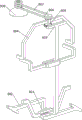
As a further preferable scheme, the device further comprises a rotating assembly, wherein the rotating assembly comprises: the fourth supporting block is arranged between one sides of the upper parts of the guide blocks, and the fourth supporting block is also arranged between one sides of the upper parts of the first supporting frames; the wedge-shaped rods are arranged between the fourth supporting blocks in a sliding mode, and the wedge-shaped rods on the same side are respectively matched with the two sides of the sliding rod; the upper part of the wedge-shaped rod is provided with a first rack; a second support rod is arranged between one sides of the upper parts of the first support frames; the middle part of the second support rod is rotatably provided with a first gear, and the first gear is meshed with the first rack; the spray head and the first gear are both provided with a second driving wheel; a second belt is wound between the second driving wheels.
The invention has the advantages that: under the action of the shaking component, people place earthworms in the cleaning frame, water is injected into the water storage frame, people step on the pedal downwards, the pedal can drive the slide rod to move downwards, the slide rod can drive the ratchet bar to move downwards, when the ratchet bar is contacted with the ratchet wheel, the ratchet wheel can be driven to rotate, the ratchet wheel can drive the first driving wheel, the first belt, the bevel gear and the rotary table to rotate, and when the rotary table rotates, the push block can be driven to move left and right, the placing frame and the cleaning frame can move left and right, so that the earthworms are shaken, and soil on the surfaces of the earthworms is shaken off; further, under the action of the flushing component, when people move the first piston downwards, water in the piston cylinder can flow into the spray head through the water outlet pipe under the action of the second one-way valve, and the spray head can spray the water onto the surface of the earthworm, so that cleaning work is performed; further, under the effect of pushing down the subassembly, when the slide bar lapse and the slider contact, can drive the slider lapse, under the cooperation of pulley, the slider can drive stay cord and scraper blade and move to the rear side, thereby impurity such as earth on the filter screen are clear away to the scraper blade to people's work efficiency has been improved.
Drawings
Fig. 1 is a schematic perspective view of the present invention.
Fig. 2 is a schematic perspective view of another perspective structure according to the present invention.
FIG. 3 is a schematic diagram of a first partial structure according to the present invention.
FIG. 4 is a second partial structure diagram of the present invention.
FIG. 5 is a third partial structural diagram of the present invention.
FIG. 6 is a schematic diagram of a fourth partial structure of the present invention.
FIG. 7 is a schematic diagram of a fifth partial structure according to the present invention.
FIG. 8 is a schematic diagram of a sixth partial structure according to the present invention.
FIG. 9 is a schematic diagram of a seventh partial structure according to the present invention.
Number designation in the figures: 1-base, 2-shaking assembly, 201-first support frame, 202-rotating disc, 203-push block, 204-placing frame, 205-cleaning frame, 3-driving assembly, 301-first guide bar, 302-sliding bar, 303-first spring, 304-pedal, 305-guide block, 306-ratchet bar, 307-second spring, 308-rotating shaft, 309-ratchet wheel, 310-first driving wheel, 311-first belt, 312-first support block, 313-bevel gear, 4-water storage assembly, 401-first support bar, 402-placing table, 403-water storage frame, 404-filter screen, 5-flushing assembly, 501-second support frame, 502-piston cylinder, 503-first piston, 504-first check valve, 505-a water inlet pipe, 506-a second one-way valve, 507-a water outlet pipe, 508-a spray head, 6-a pressing component, 601-a second supporting block, 602-a pressing rod, 603-a third spring, 604-a third supporting block, 605-a pressing block, 606-a torsion spring, 7-a cleaning component, 701-a sliding groove block, 702-a scraping plate, 703-a pulling rope, 704-a fourth spring, 705-a pulley, 706-a second guide rod, 707-a sliding block, 8-a rotating component, 801-a fourth supporting block, 802-a wedge-shaped rod, 803-a first rack, 804-a second supporting rod, 805-a first gear, 806-a second transmission wheel and 807-a second belt.
Detailed Description
In order to make the objects, technical solutions and advantages of the embodiments of the present invention clearer, the technical solutions in the embodiments of the present invention will be clearly and completely described below with reference to the drawings in the embodiments of the present invention, and it is obvious that the described embodiments are some, but not all, embodiments of the present invention. All other embodiments, which can be derived by a person skilled in the art from the embodiments given herein without making any creative effort, shall fall within the protection scope of the present invention.
Example 1
The embodiment discloses an earth cleaning equipment is used in production of energy-concerving and environment-protective earthworm, as shown in figure 1, figure 2, figure 3, figure 4, figure 5 and figure 6, including base 1, rock subassembly 2, drive assembly 3, water storage component 4 and washing subassembly 5, the rear side is equipped with and rocks subassembly 2 on base 1, is equipped with drive assembly 3 on the base 1, and the middle part is equipped with water storage component 4 on the base 1, is equipped with washing subassembly 5 on the water storage component 4.
The shaking component 2 comprises a first support frame 201, a turntable 202, a push block 203, a placing frame 204 and a cleaning frame 205, the first support frame 201 is arranged on the base 1 in a bilateral symmetry mode on the rear side, the turntable 202 is arranged on the front side of the upper portion of the first support frame 201 in an equal rotating mode, the push block 203 is arranged on the upper portion of the first support frame 201 in an equal sliding mode, the push block 203 is respectively matched with the turntable 202 in a sliding mode, the placing frame 204 is arranged between the push blocks 203, and the cleaning frame 205 is arranged at the top of the placing frame 204.
The driving component 3 comprises a first guide rod 301, a slide rod 302, a first spring 303, a pedal 304, a guide block 305, a ratchet bar 306, a second spring 307, a rotating shaft 308, a ratchet 309, a first driving wheel 310, a first belt 311, a first supporting block 312 and a bevel gear 313, the first guide rod 301 is symmetrically arranged on the front side of the base 1, the slide rod 302 is slidably arranged between the upper parts of the first guide rods 301, the first spring 303 is connected between the left side and the right side of the slide rod 302 and the base 1, the first spring 303 is respectively sleeved on the first guide rod 301, the pedal 304 is arranged in the middle part of the front side of the slide rod 302, the guide block 305 is symmetrically arranged on the rear side of the base 1, the guide block 305 is slidably matched with the slide rod 302, the ratchet bar 306 is symmetrically arranged on the left side and the rear side of the upper part of the slide rod 302, the second spring 307 is symmetrically connected between the ratchet bar 306 and the slide rod 302, the second spring 307 is respectively sleeved on the ratchet bar 306, the rotating shaft 308 is rotatably arranged between the upper portions of the first support frames 201, ratchet wheels 309 are arranged on the left side and the right side of the rotating shaft 308, ratchet wheels 309 on the same side are respectively matched with ratchet racks 306, first support blocks 312 are arranged on the outer sides of the upper portions of the first support frames 201, bevel gears 313 are rotatably arranged on the outer sides of the first support blocks 312, bevel gears 313 are also arranged at the bottoms of the turntables 202, the bevel gears 313 on the same side are meshed with each other, first drive wheels 310 are arranged on the inner sides of the bevel gears 313 on the lower side, first drive wheels 310 are also arranged on the left side and the right side of the rotating shaft 308, and first belts 311 are wound between the first drive wheels 310 on the same side.
The water storage assembly 4 comprises first support rods 401, a placing table 402, a water storage frame 403 and a filter screen 404, the first support rods 401 are arranged on the left side and the right side of the upper middle part of the base 1, the placing table 402 is arranged between the upper parts of the first support rods 401, the water storage frame 403 is arranged on the top of the placing table 402, and the filter screen 404 is arranged on the upper side of the water storage frame 403.
The flushing component 5 comprises a second support frame 501, a piston cylinder 502, a first piston 503, a first check valve 504, a water inlet pipe 505, a second check valve 506, a water outlet pipe 507 and a spray head 508, wherein the second support frame 501 is arranged at the top of the first support frame 201, the piston cylinder 502 is arranged on the second support frame 501, the first piston 503 is arranged on the piston cylinder 502 in a sliding mode, the first check valve 504 is arranged on the lower side of the outside of the piston cylinder 502, the water inlet pipe 505 is connected between the first check valve 504 and the water storage frame 403, the second check valve 506 is arranged on the inner side of the lower portion of the piston cylinder 502, the spray head 508 is arranged between the upper portion of the second support frame 501 in a rotating mode, and the water outlet pipe 507 is connected between the spray head 508 and the second check valve 506.
People place earthworms in the cleaning frame 205, water is injected into the water storage frame 403, people step the pedal 304 downwards, the pedal 304 drives the slide rod 302 to move downwards, the first spring 303 deforms, the slide rod 302 drives the ratchet bar 306 to move downwards, when the ratchet bar 306 is contacted with the ratchet wheel 309, the ratchet wheel 309 drives the first transmission wheel 310 and the first belt 311 to rotate, the first transmission wheel 310 drives the bevel gear 313 and the turntable 202 to rotate, when the turntable 202 rotates, the push block 203 is driven to move left and right, the push block 203 drives the placing frame 204 and the cleaning frame 205 to move left and right, so that the earthworms shake, soil on the surfaces of the earthworms is shaken off, when people release the pedal 304, under the reset action of the first spring 303, the slide rod 302 and the pedal 304 are driven to move upwards to reset, the slide rod 302 drives the ratchet bar 306 to move upwards, under the action of the second spring 307, make ratchet 309 can not rotate, then people lift first piston 503 upwards, under the effect of first check valve 504, water in the water storage frame 403 can flow into in the piston cylinder 502 through inlet tube 505, when people move first piston 503 downwards, under the effect of second check valve 506, water in the piston cylinder 502 can flow into shower nozzle 508 through outlet pipe 507, shower nozzle 508 can be with water shower to the earthworm surface, thereby carry out cleaning work, water after spraying can flow into on the filter screen 404 downwards, under the effect of filter screen 404, make filtered water flow into in the water storage frame 403 again, thereby realized water cycle, people's availability factor has been improved.
Example 2
On the basis of embodiment 1, as shown in fig. 7, 8 and 9, the pressing device further includes a pressing assembly 6, the pressing assembly 6 includes a second supporting block 601, a pressing rod 602, a third spring 603, a third supporting block 604, a pressing block 605 and a torsion spring 606, the second supporting block 601 is disposed on the outer side of the upper portion of the first supporting frame 201, the pressing rods 602 are disposed on the outer side of the second supporting block 601 in a sliding manner, the pressing rods 602 and the sliding rods 302 are engaged with each other, the third springs 603 are connected between the second supporting block 601 and the pressing rods 602 on the same side, the third springs 603 are respectively sleeved on the pressing rods 602, the third supporting blocks 604 are symmetrically disposed on the outer side of the second supporting frame 501, the pressing blocks 605 are rotatably disposed on the outer side of the third supporting block 604, the pressing blocks 605 and the pressing rods 602 on the same side are engaged with each other, the pressing blocks 605 and the first piston 503 on the same side are respectively slidably engaged with each other, and the torsion springs 606 are connected between the pressing blocks 605 and the third supporting block 604 on the same side, the torsion springs 606 are respectively sleeved on the third supporting blocks 604.
When the sliding rod 302 moves downwards to contact with the pressing rod 602, the pressing rod 602 is driven to move downwards, the third spring 603 deforms, when the pressing rod 602 moves downwards to contact with the pressing block 605, the pressing block 605 is driven to turn over in the forward direction, the pressing block 605 is deformed by the torsion spring 606 to drive the first piston 503 to move downwards, so that people can operate more conveniently, when the sliding rod 302 moves upwards to separate from the pressing rod 602, the pressing rod 602 can be driven to move upwards to reset under the reset action of the third spring 603, when the pressing rod 602 separates from the pressing block 605, the pressing block 605 can be driven to turn over reversely to reset under the reset action of the torsion spring 606, and the pressing block 605 can drive the first piston 503 to move upwards to reset.
The cleaning assembly 7 comprises a sliding groove block 701, a scraping plate 702, a pull rope 703, a fourth spring 704, a pulley 705, a second guide rod 706 and a sliding block 707, the sliding groove block 701 is arranged on the inner side of the first support frame 201, the scraping plate 702 is arranged between the front sides of the sliding groove blocks 701 in a sliding mode, the fourth spring 704 is connected between the left side and the right side of the scraping plate 702 and the sliding groove blocks 701, the pulley 705 is arranged on the inner side of the upper portion of the guide block 305, the second guide rods 706 are symmetrically arranged on the left side and the right side of the upper rear side of the base 1, the sliding block 707 is arranged on the second guide rod 706 in a sliding mode, the sliding block 707 is matched with the sliding rod 302, and the pull rope 703 is connected between the sliding block 707 and the scraping plate 702 through the pulley 705.
When slide bar 302 moves down and slider 707 contact, can drive slider 707 move down, under the cooperation of pulley 705, slider 707 can drive stay cord 703 and scraper blade 702 and move to the rear side, fourth spring 704 takes place deformation, thereby impurity such as earth on the scraper blade 702 with filter screen 404 is clear away, thereby people's work efficiency has been improved, when slide bar 302 rebound and slider 707 break away from, because under the reset action of fourth spring 704, can drive scraper blade 702 and stay cord 703 and move to the rear side and reset, stay cord 703 can drive slider 707 rebound to reset.
The spray head further comprises a rotating assembly 8, the rotating assembly 8 comprises a fourth supporting block 801, a wedge rod 802, a first rack 803, a second supporting rod 804, a first gear 805, a second transmission wheel 806 and a second belt 807, the fourth supporting block 801 is arranged between the rear sides of the upper portions of the pulleys 705, the fourth supporting block 801 is also arranged between the rear sides of the upper portions of the first supporting frames 201, the wedge rod 802 is arranged between the fourth supporting blocks 801 in a sliding mode, the wedge rod 802 on the same side is matched with the left side and the right side of the sliding rod 302 respectively, the first rack 803 is arranged on the upper portion of the wedge rod 802, the second supporting rod 804 is arranged between the rear sides of the upper portions of the first supporting frames 201, the first gear 805 is rotatably arranged in the middle of the second supporting rod 804, the first gear 805 is meshed with the first rack 803, the spray head 508 and the first gear 805 are both provided with the second transmission wheel 806, and the second belt 807 is wound between the second transmission wheels 806.
When the sliding bar 302 moves downwards to contact with the wedge bar 802, the wedge bar 802 is driven to move towards the right side, the wedge bar 802 drives the first rack 803 to move towards the right side, the first rack 803 drives the first gear 805 to rotate in the forward direction, the first gear 805 drives the second driving wheel 806 and the second belt 807 to rotate, the second driving wheel 806 drives the spray head 508 to rotate in the forward direction, so that the spray head 508 sprays more uniformly, thereby improving the working efficiency of people, when the sliding bar 302 moves upwards to contact with the wedge bar 802, the wedge bar 802 is driven to move towards the left side, the wedge bar 802 drives the first rack 803 to move towards the left side, the first rack 803 drives the first gear 805 to rotate in the reverse direction, and the first gear 805 drives the second driving wheel 806, the second belt 807 and the spray head 508 to rotate in the reverse direction, so that the slide bar is reset.
Finally, it should be noted that: the above examples are only intended to illustrate the technical solution of the present invention, but not to limit it; although the present invention has been described in detail with reference to the foregoing embodiments, it will be understood by those of ordinary skill in the art that: the technical solutions described in the foregoing embodiments may still be modified, or some technical features may be equivalently replaced; and such modifications or substitutions do not depart from the spirit and scope of the corresponding technical solutions of the embodiments of the present invention.
Claims (8)
1. An energy-saving and environment-friendly earth cleaning device for earthworm production is characterized by comprising a base (1); the base is provided with a swinging component (2), and the swinging component (2) is arranged on one side of the base (1); the driving component (3) is arranged on the base (1); the upper middle part of the base (1) is provided with a water storage component (4); the flushing component (5) is arranged on the water storage component (4).
2. The earth cleaning equipment for the production of the energy-saving and environment-friendly earthworms as claimed in claim 1, wherein the shaking assembly (2) comprises a first supporting frame (201), and the first supporting frame (201) is symmetrically arranged on one side of the base (1); the turntable (202) is rotatably arranged on one side of the upper part of the first support frame (201); the upper parts of the first supporting frames (201) are respectively provided with a pushing block (203) in a sliding manner, and the pushing blocks (203) are respectively in sliding fit with the rotating disc (202); the placing frames (204) are arranged between the pushing blocks (203); the top of the cleaning frame (205) and the placing frame (204) are provided with the cleaning frame (205).
3. An energy-saving environment-friendly earthworm production soil cleaning device according to claim 2, wherein the driving assembly (3) comprises a first guide rod (301), and the first guide rod (301) is symmetrically arranged on one side of the base (1); the sliding rod (302) is arranged between the upper parts of the first guide rods (301) in a sliding manner; the first spring (303) is connected between the two sides of the sliding rod (302) and the base (1), and the first spring (303) is sleeved on the first guide rod (301) respectively; the middle part of one side of the sliding rod (302) is provided with a pedal (304); the guide block (305) is symmetrically arranged on one side of the base (1), and the guide block (305) is in sliding fit with the sliding rod (302); the ratchet bar (306) is symmetrically and slidably arranged on one side of the upper part of the sliding rod (302); the second springs (307) are symmetrically connected between the ratchet bar (306) and the sliding rod (302), and the second springs (307) are respectively sleeved on the ratchet bar (306); a rotating shaft (308), wherein the rotating shaft (308) is rotatably arranged between the upper parts of the first support frames (201); the ratchet wheel (309) is arranged on two sides of the rotating shaft (308), and the ratchet wheel (309) on the same side is matched with the ratchet bar (306) respectively; the outer sides of the upper parts of the first support frames (201) are provided with first support blocks (312); the outer sides of the first supporting blocks (312) are respectively and rotatably provided with the bevel gears (313), the bottoms of the turntables (202) are respectively provided with the bevel gears (313), and the bevel gears (313) on the same side are mutually meshed; the inner sides of the lower bevel gears (313) of the first transmission wheels (310) and the two sides of the rotating shaft (308) are both provided with the first transmission wheels (310); the first belts (311) are wound between the first transmission wheels (310) on the same side.
4. An energy-saving and environment-friendly earthworm production soil cleaning device according to claim 3, wherein the water storage component (4) comprises a first support rod (401), and the first support rods (401) are arranged on two sides of the upper middle part of the base (1); a placing table (402), wherein the placing table (402) is arranged between the upper parts of the first supporting rods (401); the top of the placing table (402) is provided with a water storage frame (403); the filter screen (404) is arranged on the upper side of the filter screen (404) and the water storage frame (403).
5. An energy-saving and environment-friendly earthworm production soil cleaning device according to claim 4, wherein the flushing assembly (5) comprises a second support frame (501), the second support frame (501) is arranged on the top of each first support frame (201); the piston cylinder (502) and the second support frame (501) are respectively provided with a piston cylinder (502); the first piston (503) is arranged on the piston cylinder (502) in a sliding manner; the lower sides of the exterior of the piston cylinders (502) are respectively provided with a first check valve (504); the water inlet pipe (505) is connected between the first one-way valve (504) and the water storage frame (403); the inner sides of the lower parts of the piston cylinders (502) are respectively provided with a second one-way valve (506); the spray head (508), the spray head (508) is rotatably arranged between the upper parts of the second supporting frames (501); and water outlet pipes (507) are connected between the water outlet pipe (507) and the second one-way valve (506) and the spray head (508).
6. The energy-saving environment-friendly earthworm production soil cleaning equipment according to claim 5, further comprising a pressing component (6), wherein the pressing component (6) comprises a second supporting block (601), and the second supporting block (601) is arranged on the outer side of the upper part of the first supporting frame (201); the outer sides of the second supporting blocks (601) are respectively provided with a pressing rod (602) in a sliding manner, and the pressing rods (602) are matched with the sliding rods (302); the third springs (603) are connected between the second supporting block (601) and the pressing rod (602) on the same side, and the third springs (603) are respectively sleeved on the pressing rod (602); the outer sides of the second supporting frames (501) are symmetrically provided with third supporting blocks (604); the pressing blocks (605) are rotatably arranged on the outer sides of the third supporting blocks (604), the pressing blocks (605) on the same side are matched with the pressing rods (602), and the pressing blocks (605) on the same side are respectively in sliding fit with the first pistons (503); and the torsion springs (606) are connected between the pressing blocks (605) on the same side and the third supporting block (604), and the torsion springs (606) are respectively sleeved on the third supporting block (604).
7. The energy-saving and environment-friendly earthworm production soil cleaning equipment according to claim 6, further comprising a cleaning component (7), wherein the cleaning component (7) comprises a chute block (701), and the inside of the first support frame (201) is provided with the chute block (701); the scraper (702) is arranged between one sides of the sliding groove blocks (701) in a sliding manner; the fourth spring (704) is connected between the two sides of the scraper (702) and the chute block (701); the pulley (705) is arranged on the inner side of the upper part of the guide block (305); a second guide rod (706), wherein the second guide rod (706) is symmetrically arranged on one side of the base (1); the sliding blocks (707) are arranged on the second guide rods (706) in a sliding mode, and the sliding blocks (707) are matched with the sliding rods (302); the pull rope (703) is connected between the sliding block (707) and the scraper (702) through a pulley (705).
8. An energy-saving and environment-friendly earthworm production soil cleaning device according to claim 7, further comprising a rotating component (8), wherein the rotating component (8) comprises a fourth supporting block (801), the fourth supporting block (801) is arranged between one sides of the upper parts of the guide blocks (305), and the fourth supporting block (801) is also arranged between one sides of the upper parts of the first supporting frames (201); the wedge-shaped rods (802) are arranged between the wedge-shaped rods (802) and the fourth supporting block (801) in a sliding manner, and the wedge-shaped rods (802) on the same side are respectively matched with the two sides of the sliding rod (302); the upper part of the wedge-shaped rod (802) is provided with a first rack (803); a second supporting rod (804), wherein the second supporting rod (804) is arranged between one sides of the upper parts of the first supporting frames (201); the middle part of the second support rod (804) is rotatably provided with a first gear (805), and the first gear (805) is meshed with the first rack (803); the second driving wheel (806), the spray head (508) and the first gear (805) are provided with the second driving wheel (806); a second belt (807), and the second belt (807) is wound between the second transmission wheels (806).
Priority Applications (1)
| Application Number | Priority Date | Filing Date | Title |
|---|---|---|---|
| CN202110769670.XA CN113399357A (en) | 2021-07-08 | 2021-07-08 | Energy-concerving and environment-protective earth cleaning equipment for earthworm production |
Applications Claiming Priority (1)
| Application Number | Priority Date | Filing Date | Title |
|---|---|---|---|
| CN202110769670.XA CN113399357A (en) | 2021-07-08 | 2021-07-08 | Energy-concerving and environment-protective earth cleaning equipment for earthworm production |
Publications (1)
| Publication Number | Publication Date |
|---|---|
| CN113399357A true CN113399357A (en) | 2021-09-17 |
Family
ID=77685475
Family Applications (1)
| Application Number | Title | Priority Date | Filing Date |
|---|---|---|---|
| CN202110769670.XA Withdrawn CN113399357A (en) | 2021-07-08 | 2021-07-08 | Energy-concerving and environment-protective earth cleaning equipment for earthworm production |
Country Status (1)
| Country | Link |
|---|---|
| CN (1) | CN113399357A (en) |
Cited By (1)
| Publication number | Priority date | Publication date | Assignee | Title |
|---|---|---|---|---|
| CN114307333A (en) * | 2021-12-13 | 2022-04-12 | 刘智航 | Water quality research draws equipment with sewage impurity |
-
2021
- 2021-07-08 CN CN202110769670.XA patent/CN113399357A/en not_active Withdrawn
Cited By (1)
| Publication number | Priority date | Publication date | Assignee | Title |
|---|---|---|---|---|
| CN114307333A (en) * | 2021-12-13 | 2022-04-12 | 刘智航 | Water quality research draws equipment with sewage impurity |
Similar Documents
| Publication | Publication Date | Title |
|---|---|---|
| CN113445444B (en) | Energy-concerving and environment-protective roadside warning sign device of using | |
| CN208406278U (en) | A kind of high-efficiency filtration systems of cold pressing rapeseed oil | |
| CN112425798A (en) | Edible potato cleaning device | |
| CN110352903A (en) | A kind of fish jar inner-wall cleaning device | |
| CN112570363A (en) | Department of traditional chinese medicine is with belt cleaning device of energy-concerving and environment-protective type | |
| CN113399357A (en) | Energy-concerving and environment-protective earth cleaning equipment for earthworm production | |
| CN110140979B (en) | Sweet potato scrubbing device | |
| CN111758974A (en) | Equipment for rapidly cleaning potatoes | |
| CN106868770B (en) | A kind of clothing cloth extruding cleaning equipment in tailoring machinery field | |
| CN211230392U (en) | Oil removing device for cleaning oil pumping unit | |
| CN112586770A (en) | Bean cleaning device and bean product processing method | |
| CN207591524U (en) | A kind of air purification cleaner in the construction site of environmental protection | |
| CN113856298B (en) | Villages and small towns are liftable grid for sewage treatment | |
| CN112826104B (en) | Agricultural product grape processing is with equipment of quick washing pesticide dirt | |
| CN111889411B (en) | Cortex cinnamomi japonici skin removing device | |
| CN213965225U (en) | Water supply equipment for chemical distillation tower | |
| CN113558982A (en) | High-temperature decocting pot | |
| CN209331067U (en) | It is a kind of to remove shelled fresh shrimp cleaning device with filtering function | |
| CN112524096A (en) | Emergency water pumping machine for emergency rescue and drainage and use method thereof | |
| CN112741341A (en) | Leaf vegetable surface pesticide residue cleaning equipment and cleaning method with good cleaning effect | |
| CN117074397B (en) | Detection equipment for Chinese chives pesticide residues | |
| CN2714123Y (en) | Discharging and filter cloth cleaning system for pressing filter | |
| CN110250528A (en) | A kind of cider preparation facilities | |
| CN218551216U (en) | Pear soak device is used in pear cream production | |
| CN220936663U (en) | Vegetable harvesting and mud removing device |
Legal Events
| Date | Code | Title | Description |
|---|---|---|---|
| PB01 | Publication | ||
| PB01 | Publication | ||
| SE01 | Entry into force of request for substantive examination | ||
| SE01 | Entry into force of request for substantive examination | ||
| WW01 | Invention patent application withdrawn after publication |
Application publication date: 20210917 |
|
| WW01 | Invention patent application withdrawn after publication |