Method for processing fillet of internal intersecting line
Technical Field
The invention belongs to the technical field of machining, and particularly relates to a method for machining a fillet of an internal intersecting line.
Background
The pump body of the reciprocating pump is provided with a plurality of intersected water channels, namely intersected inner holes from the machining point of view; when a lateral hole (generally smaller in inner diameter than the main channel hole) is connected and communicated with the lateral side of one main channel hole, the inner end of the lateral hole intersects with the inner wall of the main channel hole to form a boundary line, and the boundary line is a closed space curve, namely an inner intersecting line. In the reciprocating pump use, inside fluid pressure is very big, for avoid stress concentration, the condition that local closed angle on the intersecting line collapses garrulous in the appearance, can carry out radius angle transition in the design in intersecting line position department including, and this structural processing can improve the service strength and the life-span of pump.
At present, fillet transition treatment at the position of an internal intersecting line always depends on manual filing and forming by a bench worker or manual grinding and forming by an electric tool (such as an electric grinding head). This is because the inner intersecting line is located inside the pump body, which is inconvenient for mechanical equipment to perform material removal processing such as cutter milling. However, the manual forming has the problems of low efficiency and poor quality consistency of the polished round angle. With the use of numerical control technology and numerical control equipment, spatial curved surfaces can be milled and processed in reasonable manners such as isoparametric milling, curved surface milling and the like, for example, CN106647635A, CN110968042A and CN1588257A are involved, and a process technician also considers using the numerical control equipment to process a fillet at the position of an internal intersecting line; however, currently commonly used three-dimensional modeling (with numerical control machining path setting and program post-processing functions) software such as UG, mastercam, caxa, cimatron e and the like can only set and generate a tool machining trajectory of a spatial curved surface without matrix interference above a machined surface and generate a machining program, and cannot process numerical control machining of the spatial curved surface with matrix interference above the machined surface and cannot produce the tool machining trajectory.
Referring to fig. 1, a fillet (not shown) at the position of an internal intersecting line 4 where a main channel hole 2 and a lateral hole 3 intersect can only be considered from the outer end of the lateral hole 3 to the inside and is machined by using a formed straight-shank T-shaped slot milling cutter 7 (disc milling cutter), and the fillet at the position is shielded and interfered by a part of a base body 1 provided with the lateral hole 3, which is the condition that the conventional software cannot directly process the fillet. The cutter path of the space curved surface is formed by a large number of continuous breakpoints (the higher the machining precision is, the more the breakpoints are), and manual writing cannot be carried out. The invention aims to solve the problem that how to generate an available tool machining track based on the existing software so as to obtain a machining program, reasonably select a tool, clamp a machined workpiece, set a machining coordinate of equipment and finally complete the numerical control machining of a circular bead at the position of an internal intersecting line.
Disclosure of Invention
Aiming at the defects in the prior art, the invention aims to provide a method for processing the fillet of the inner intersecting line, so that the problem that the existing modeling programming software cannot process numerical control processing of the fillet at the position of the inner intersecting line is solved, and the effects of replacing manual forming by numerical control processing, improving quality and increasing efficiency are achieved.
In order to solve the technical problems, the invention adopts the following technical scheme:
the inner intersecting line fillet machining method comprises the following process steps:
1) modeling; the built three-dimensional model comprises a base body, wherein a main channel hole and a lateral hole which is intersected and communicated with the main channel hole at the radial side of the main channel hole are formed in the base body, and the axial lines of the lateral hole and the main channel hole are intersected; an inner intersecting line is formed between the inner end of the lateral hole and the inner wall of the main channel hole, and the outer end of the lateral hole penetrates through the base body;
2) rounding the inner intersecting line; forming a space curved surface to be processed along the fillet of the internal intersecting line;
3) establishing a first coordinate system for generating a tool machining track;
establishing a second coordinate system for post-processing generation of a machining program;
the zero point of the first coordinate system is located on the intersection point of the axes of the lateral hole and the main channel hole, the zero point of the second coordinate system is located on the axis of the lateral hole and at the outer end of the lateral hole, the Z axis of the second coordinate system is collinear with the axis of the lateral hole, and the positive direction of the Z axis of the second coordinate system faces to the direction far away from the main channel hole; the Z axis of the first coordinate system is collinear with the axis of the lateral hole, and the positive direction of the Z axis of the first coordinate system is opposite to the positive direction of the Z axis of the second coordinate system;
4) removing the base part above the zero point of the Z axis of the first coordinate system;
5) generating a tool machining track of the space curved surface by using a first coordinate system; the cutter corresponding to the cutter processing track is an end mill;
6) carrying out post-processing on the tool processing track by using a second coordinate system and generating a processing program;
7) a T-shaped slot milling cutter is used in actual processing on numerical control equipment; setting zero points in the X direction and the Y direction on the numerical control equipment corresponding to the zero point of the second coordinate system, wherein the zero point in the Z direction is set on the upper surface of a disc of the T-shaped slot milling cutter; the outer diameter of the disc of the T-shaped slot milling cutter corresponds to the outer diameter of the end milling cutter.
Further perfecting the technical scheme, the step 7) also comprises the following steps: fixing and clamping a solid part on a table top of a numerical control device, wherein the solid part is provided with a corresponding lateral hole and an inner intersecting line; the lateral hole on the solid part is vertical and the outer end of the lateral hole is upward so as to facilitate feeding; the length of the handle part of the T-shaped slot milling cutter is greater than the depth of the lateral hole on the solid part; the difference between the radius of the disc of the T-shaped slot milling cutter and the radius of the handle is larger than the radius of the fillet; and transmitting the processing program to the numerical control equipment and operating the processing program on the numerical control equipment to finish the numerical control milling processing of the space curved surface.
Further, the solid part has a horizontal plane thereon and the horizontal plane corresponds to the zero point of the Z-axis of the second coordinate system.
Further, between step 6) and step 7), further comprising: and 6.1) modifying a feed point when the machining program starts and a retraction point when the machining program finishes so as to avoid the cutter collision of the T-shaped slot milling cutter used in the actual machining.
Further, the upper surface of the disc of the T-shaped slot milling cutter is provided with a cutting edge.
Further, before generating the tool machining path of the space curved surface by using the first coordinate system in step 5), the method further includes: creating a tool, selecting a machining mode, selecting a coordinate system, setting a contour, selecting a tolerance and a margin, selecting a tool path track, selecting a step pitch and setting a Z value limit.
Compared with the prior art, the invention has the following beneficial effects:
1. according to the method for processing the fillet of the internal intersecting line, the problem that numerical control processing of the fillet at the position of the internal intersecting line cannot be processed by existing modeling programming software is solved through the coordinate in the modeling programming process and flexible conversion and adaptive application of a programming tool and a tool used for actual processing.
2. The processing method of the fillet of the inner intersecting line realizes that the fillet of the inner intersecting line is formed manually instead of manually by numerical control processing, greatly improves the efficiency, and has good processing quality consistency.
3. The method for processing the inner intersecting line fillet can also be suitable for numerical control cutting processing of other similar inner curved surfaces.
Drawings
FIG. 1 is a schematic diagram of a substrate with a main channel hole and a lateral hole formed therein, and is also used for reference of the structure mentioned in the background art;
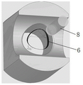
FIG. 2 is a schematic representation of a particular embodiment with portions of the base removed and the internal intersecting lines rounded off to form a spatial curve;
FIG. 3 is a cross-sectional view of FIG. 2;
FIG. 4 is a screenshot illustrating the parameter settings of the programming software involved in step 5) in an exemplary embodiment;
FIG. 5 is a schematic diagram of step 5) of generating a tool machining path by a set end mill in an embodiment;
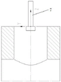
FIG. 6 is a schematic diagram illustrating X, Y zero points and a Z-direction zero point of the tool on the numerical control device in step 7) of the embodiment;
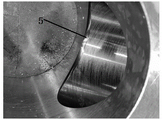
FIG. 7 is a diagram illustrating the effect of a spatial curved surface with rounded corners at locations of internal intersecting lines formed by numerical control machining according to an embodiment;
the device comprises a base body 1, a main channel hole 2, a lateral hole 3, an inner intersecting line 4, a space curved surface 5, a cutter machining track 6, a T-shaped groove milling cutter 7 and an end milling cutter 8.
Detailed Description
The following provides a more detailed description of embodiments of the present invention, with reference to the accompanying drawings.
In the method for processing the inner intersecting line fillet according to the specific embodiment, three-dimensional modeling programming software is installed on a computer, and in the embodiment, the software cimatron e 11.0 is taken as an example, and the method comprises the following process steps:
1) operating Cimatron E11.0 on a computer, performing three-dimensional modeling, and establishing a three-dimensional model, which can refer to FIG. 1; the built three-dimensional model comprises a base body 1, wherein a main channel hole 2 and a lateral hole 3 which is communicated with the main channel hole 2 in an intersecting manner at the radial side of the main channel hole 2 are formed in the base body 1, and the axial lines of the lateral hole 3 and the main channel hole 2 are intersected and mutually perpendicular; the inner end of the lateral hole 3 and the inner wall of the main channel hole 2 form an inner intersecting line 4, the outer end of the lateral hole 3 penetrates through the corresponding outer surface of the base body 1, and the outer surface is a plane perpendicular to the axis of the lateral hole 3.
Referring to fig. 2 and fig. 3,
2) rounding the inner intersecting line 4, wherein the radius of the rounded corner is R3 in the embodiment; a space curved surface 5 to be processed is formed along the fillet of the internal intersecting line 4;
in the embodiment, the lateral hole 3 is smaller than the main channel hole 2, the inner diameter of the main channel hole 2 is phi 103H8, the inner diameter of the lateral hole 3 is phi 79 +/-0.1, and the distance from the plane of the base 1 at the outer end of the lateral hole 3 to the axis of the main channel hole 2 is 130;
3) establishing a first coordinate system for generating the tool machining trajectory 6, see the USC18 coordinate system in fig. 3;
establishing a second coordinate system for the post-processing generation machining program, wherein the second coordinate system is shown as a MODEL coordinate system in FIG. 3;
a zero point of a first coordinate system (USC 18) is positioned on an intersection point of the axes of the lateral hole 3 and the main channel hole 2, a zero point of a second coordinate system (MODEL) is positioned on the axis of the lateral hole 3 and at the outer end of the lateral hole 3 (specifically, on an intersection point of the axis of the lateral hole 3 and the outer end of the lateral hole 3 penetrating through a corresponding plane of the base body 1), a Z axis of the second coordinate system (MODEL) is collinear with the axis of the lateral hole 3, and a positive direction of the Z axis of the second coordinate system (MODEL) faces away from the main channel hole 2; the Z-axis of the first coordinate system (USC 18) is collinear with the axis of the lateral hole 3 and the positive direction of the Z-axis of the first coordinate system (USC 18) is opposite to the positive direction of the Z-axis of the second coordinate system (mode);
4) the part of the substrate 1 above the zero point of the Z axis of the first coordinate system (USC 18) is removed, thus removing the part of the substrate 1 above the processing of the blocked (interfering) spatial curved surface 5 for subsequent software recognition processing and enabling generation of the tool processing trajectory 6 of said spatial curved surface 5 in the first coordinate system (USC 18). In implementation, based on the difference of modeling habits, a substrate 1 containing only half of the main channel holes 2 can be directly created, that is, the substrate 1 form of fig. 2 is directly formed, and the method is not limited.
Referring to fig. 4 and fig. 5,
5) generating a tool machining track 6 of the space curved surface 5 in a first coordinate system (USC 18); the cutter corresponding to the cutter processing track 6 is the end mill 8;
specifically, it can be seen from fig. 4 that, before step 5) generating the tool machining trajectory 6 of the space curved surface 5 in the first coordinate system (USC 18), the method further includes: the method comprises the following steps of creating a cutter, selecting a machining mode, selecting a coordinate system, setting a contour, selecting tolerance and allowance, selecting a cutter path track, selecting a step pitch, setting Z value limit and the like, and the operations are reasonably set, so that the operations are not repeated in the prior art.
6) Carrying out post-processing on the tool machining track 6 by using a second coordinate system (MODEL) and generating a machining program;
the program part which is required for actual processing and cannot be manually edited is mainly a tool path part which is generated in the processing program and has continuous large number of breakpoints of the processing space curved surface 5, and a feed point at the beginning and a withdrawal point at the end of the processing program can be modified manually appropriately so as to avoid collision of the T-shaped slot milling cutter 7 used for actual processing with the base body 1 (solid part) during feeding and withdrawal.
Referring to figure 6 of the drawings, in which,
7) a T-shaped slot milling cutter 7 is used in the actual processing on the numerical control equipment; setting zero points in the X direction and the Y direction on the numerical control equipment corresponding to the zero point of a second coordinate system (MODEL), wherein the zero point in the Z direction is set on the upper surface of a disc of the T-shaped slot milling cutter 7; the outer diameter of the disc (including the tooth portion) of the T-slot mill 7 corresponds to the outer diameter of the end mill 8.
Therefore, in actual processing, the upper edge of the peripheral teeth of the disc of the T-shaped slot milling cutter 7 is used for replacing the lower edge of the peripheral teeth of the end milling cutter 8 to mill the spatial curved surface 5, and the problem that numerical control processing of the fillet at the position of the internal intersecting line 4 cannot be processed by existing modeling programming software is solved through the coordinate in the modeling programming process, flexible conversion and adaptive application of the programming cutter and the cutter used for actual processing.
During specific operation, the step 7) further comprises the conventional operation of processing through numerical control equipment: the method comprises the following steps of (1) fixedly clamping a solid part on a table top of a numerical control device, wherein the solid part corresponds to a base body 1 and is provided with a main channel hole 2, a lateral hole 3 and an inner intersecting line 4; the lateral hole 3 on the solid part is vertical and the outer end is upward so as to facilitate the feed; it will be appreciated that the length of the shank of the T-slot mill 7 (the portion of the shank of the T-slot mill 7 which grips below the shank bt 40) is greater than the depth of the lateral bore 3 in the solid part; the difference between the disc radius of the T-shaped slot milling cutter 7 and the radius of the handle part is larger than the radius of the fillet;
when the produced machining program is manually modified and the actual machining is fed, the cutter firstly falls on the zero point of the X, Y axis of the numerical control equipment, then the cutter is lowered to the proper height of the Z axis, the machining program part of the produced machining space curved surface 5 is started to be moved, after the machining program part of the machining space curved surface 5 is moved, the cutter needs to be retracted, the cutter firstly moves to the zero point of the X, Y axis of the numerical control equipment, and then the Z axis is lifted, so that the cutter is far away from the base body 1 (solid part);
and transmitting the processing program to the numerical control equipment, running the processing program on the numerical control equipment, and forming the internal intersecting line 4 on the solid part into the space curved surface 5 through numerical control milling by using a T-shaped slot milling cutter 7.
In practice, a horizontal plane (refer to the upper plane of the solid part in fig. 6) may be pre-machined on the solid part, and the height of the horizontal plane corresponds to the zero point of the Z-axis of the second coordinate system (mode), i.e. to the corresponding plane of the modeling where the outer end of the lateral hole 3 penetrates through the substrate 1. Therefore, the length compensation of the cutter of the T-shaped slot milling cutter 7 is conveniently set, the T-shaped slot milling cutter 7 is dropped on the horizontal plane for cutter setting, then, the Z axis of the numerical control equipment is lowered by a disc thickness value of the T-shaped slot milling cutter 7, the Z-direction zero point of the second coordinate system can be set on the upper surface of the disc, and the actually input cutter length compensation value of the numerical control equipment is that the disc thickness value of the T-shaped slot milling cutter 7 is lowered at the position, so that the method is accurate and reliable.
It should be noted that if the disk of the T-slot milling cutter 7 is in a general form with only peripheral teeth, when the tool path trajectory of the spatial curved surface 5 is selected, only circular cutting, forward milling and inside-out can be selected, and the peripheral teeth of the disk of the T-slot milling cutter 7 can replace the peripheral teeth of the end mill 8 to complete milling. If the disc of the T-shaped slot milling cutter 7 does not have top teeth, the bottom teeth of the end milling cutter 8 cannot be replaced by the T-shaped slot milling cutter 7, if the upper surface of the disc of the T-shaped slot milling cutter 7 is provided with cutting edges (top teeth), the tool path track of the space curved surface 5 can be selected from inside to outside, or from outside to inside, and when the tool path track is selected from outside to inside, the top teeth of the disc of the T-shaped slot milling cutter 7 replace the bottom teeth of the end milling cutter 8 to complete milling, so that numerical control milling can be realized, and the application is more flexible.
The space curved surface 5 formed by numerical control milling can be seen in fig. 7, the consistency of the processing quality of the fillet is good, and the processing efficiency is greatly improved.
Finally, the above embodiments are only for illustrating the technical solutions of the present invention and not for limiting, although the present invention has been described in detail with reference to the preferred embodiments, it should be understood by those skilled in the art that modifications or equivalent substitutions may be made to the technical solutions of the present invention without departing from the spirit and scope of the technical solutions of the present invention, and all of them should be covered in the claims of the present invention.