CN113357618B - Lighting device - Google Patents
Lighting device Download PDFInfo
- Publication number
- CN113357618B CN113357618B CN202110651289.3A CN202110651289A CN113357618B CN 113357618 B CN113357618 B CN 113357618B CN 202110651289 A CN202110651289 A CN 202110651289A CN 113357618 B CN113357618 B CN 113357618B
- Authority
- CN
- China
- Prior art keywords
- supporting rod
- hollow cavity
- sliding seat
- support rod
- rod
- Prior art date
- Legal status (The legal status is an assumption and is not a legal conclusion. Google has not performed a legal analysis and makes no representation as to the accuracy of the status listed.)
- Active
Links
Images


Classifications
-
- F—MECHANICAL ENGINEERING; LIGHTING; HEATING; WEAPONS; BLASTING
- F21—LIGHTING
- F21V—FUNCTIONAL FEATURES OR DETAILS OF LIGHTING DEVICES OR SYSTEMS THEREOF; STRUCTURAL COMBINATIONS OF LIGHTING DEVICES WITH OTHER ARTICLES, NOT OTHERWISE PROVIDED FOR
- F21V21/00—Supporting, suspending, or attaching arrangements for lighting devices; Hand grips
- F21V21/14—Adjustable mountings
- F21V21/22—Adjustable mountings telescopic
Abstract
The invention provides a lighting device. The lighting device includes: a lamp cap; the top end of the upper support rod is connected with the lamp cap; the lower support rod is provided with a hollow cavity, and at least one part of the upper support rod extends into the hollow cavity so as to enable the upper support rod and the lower support rod to be connected in a nested manner; the damping piece is arranged on the upper supporting rod and is abutted against the inner wall surface of the hollow cavity, and when the upper supporting rod moves to a target position relative to the lower supporting rod, the damping piece can generate damping force opposite to the gravity direction of the upper supporting rod, so that the upper supporting rod stays at the target position. The invention solves the problem that the lighting device in the prior art is inconvenient to longitudinally adjust the position of the light source.
Description
Technical Field
The invention relates to the technical field of illumination, in particular to an illumination device.
Background
At present, the lighting device becomes an integral part of people's daily life. Taking a desk lamp as an example, the desk lamp used by people is mainly placed on a writing desk or a dining table for illumination.
The existing desk lamp can only reduce the vertical height of a light source by adjusting the front and rear angles, thereby realizing the longitudinal adjustment of the position of the light source. That is to say, when the light source position of needs longitudinal adjustment desk lamp, the user can only realize through the movable segment between the lamp holder of buckling desk lamp and the base, and this has influenced the use convenience of desk lamp greatly, and then influences user experience.
From the above, there is a problem in the prior art that it is inconvenient to adjust the position of the light source longitudinally.
Disclosure of Invention
The invention mainly aims to provide a lighting device to solve the problem that the lighting device in the prior art is inconvenient to longitudinally adjust the position of a light source.
In order to achieve the above object, the present invention provides an illumination device comprising: a lamp cap; the top end of the upper support rod is connected with the lamp cap; the lower support rod is provided with a hollow cavity, and at least one part of the upper support rod extends into the hollow cavity so as to enable the upper support rod and the lower support rod to be connected in a nested manner; the damping piece is arranged on the upper supporting rod and is abutted against the inner wall surface of the hollow cavity, and when the upper supporting rod moves to a target position relative to the lower supporting rod, the damping piece can generate damping force opposite to the gravity direction of the upper supporting rod, so that the upper supporting rod stays at the target position.
Further, the damping piece is a plurality of, and a plurality of damping piece intervals set up on the upper support pole.
Furthermore, the upper support rod is provided with a containing groove, the containing groove and the damping piece are correspondingly arranged, and at least one part of the damping piece is contained in the containing groove.
Further, the damping member includes: glass beads; and the elastic piece is accommodated in the accommodating groove, and two ends of the elastic piece are respectively abutted with the glass beads and the groove bottom of the accommodating groove so as to enable the glass beads to be abutted with the lower support rod.
Furthermore, the upper support rod and the lower support rod are in sliding connection.
Further, the upper support pole includes: a first link: the one end of slider and the bottom detachably of first connecting rod are connected, and the slider holding is in cavity intracavity and can slide in cavity intracavity to sliding connection between messenger's upper strut pole and the lower strut pole.
Further, the slider includes: the damping piece is arranged on the sliding seat; the linkage segment, the linkage segment is connected in order with the sliding seat, and the linkage segment is connected with the bottom detachably of first connecting rod.
Furthermore, the sliding part also comprises a plurality of balls, and the balls are arranged on the sliding seat at intervals along the sliding seat; or the sliding part also comprises a plurality of pulleys which are arranged on the sliding seat along the interval of the sliding seat.
Further, the lower support rod includes: the second connecting rod is provided with a hollow cavity; and the limiting piece is fixedly accommodated in the hollow cavity and is positioned at the top end of the second connecting rod.
Furthermore, the limiting part is provided with a central through hole, and the bottom end of the first connecting rod penetrates through the central through hole to be detachably connected with the connecting section.
Furthermore, the shape of the peripheral surface of the sliding seat is matched with the shape of the inner wall surface of the hollow cavity; and/or the outer diameter of the connecting section is smaller than that of the sliding seat so as to form a butt joint step at the connecting part of the connecting section and the sliding seat, and the first connecting rod is connected with the connecting section at the butt joint step.
Furthermore, one end of the sliding part is connected with the bottom end of the first connecting rod in a buckling mode.
By applying the technical scheme of the invention, the lighting device comprises a lamp cap, an upper supporting rod, a lower supporting rod and a damping part, wherein the top end of the upper supporting rod is connected with the lamp cap, the lower supporting rod is provided with a hollow cavity, at least one part of the upper supporting rod extends into the hollow cavity so as to enable the upper supporting rod and the lower supporting rod to be connected in a nested manner, the damping part is arranged on the upper supporting rod and abutted against the inner wall surface of the hollow cavity, when the upper supporting rod moves to a target position relative to the lower supporting rod, the damping part can generate damping force opposite to the gravity direction of the upper supporting rod so as to enable the upper supporting rod to stay at the target position, so that a user can adjust the height of the lamp cap only by moving the upper supporting rod relative to the lower supporting rod, the lighting device is convenient and rapid, and the damping part can enable the upper supporting rod to stay at the target position when the upper supporting rod moves to the target position, the requirement of the longitudinal light source position of the user is ensured, and the problem that the lighting device in the prior art is inconvenient to longitudinally adjust the light source position is solved.
Drawings
The accompanying drawings, which are incorporated in and constitute a part of this application, illustrate embodiments of the invention and, together with the description, serve to explain the invention and not to limit the invention. In the drawings:
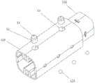
FIG. 1 shows an exploded view of a lighting device in one embodiment of the invention;
FIG. 2 is a schematic view of the damper member coupled to the upper support rod and the limiting member according to an exemplary embodiment of the present invention;
fig. 3 is a schematic structural view of the upper support rod and the lower support rod after being connected in one embodiment of the present invention.
Wherein the figures include the following reference numerals:
10. an upper support rod; 11. a first link; 12. a slider; 121. a sliding seat; 122. a connecting section; 123. a ball bearing; 13. a containing groove; 20. a lower support bar; 21. a second link; 22. a stopper; 30. a damping member; 31. glass beads; 32. an elastic member.
Detailed Description
It should be noted that, in the present application, the embodiments and features of the embodiments may be combined with each other without conflict. The present invention will be described in detail below with reference to the accompanying drawings in conjunction with embodiments.
It is noted that, unless otherwise indicated, all technical and scientific terms used herein have the same meaning as commonly understood by one of ordinary skill in the art to which this application belongs.
In the present invention, unless stated to the contrary, the use of directional terms such as "upper, lower, top, bottom" or the like, generally refers to the orientation of the components as shown in the drawings, or to the vertical, perpendicular, or gravitational orientation of the components themselves; likewise, for ease of understanding and description, "inner and outer" refer to the inner and outer relative to the profile of the components themselves, but the above directional words are not intended to limit the invention.
It is to be understood that the above-described embodiments are only a few, but not all, embodiments of the present invention. All other embodiments, which can be derived by a person skilled in the art from the embodiments given herein without making any creative effort, shall fall within the protection scope of the present invention.
The invention provides a lighting device, aiming at solving the problem that the lighting device in the prior art is inconvenient to longitudinally adjust the position of a light source.
As shown in fig. 1-3. The lighting device includes a lamp cap, an upper support rod 10, a lower support rod 20, and a damping member 30. The top end of the upper support rod 10 is connected with the lamp cap. The lower support rod 20 has a hollow cavity into which at least a portion of the upper support rod 10 extends to allow a nested connection between the upper support rod 10 and the lower support rod 20. The damping member 30 is disposed on the upper support bar 10 and abuts against an inner wall surface of the hollow chamber, and when the upper support bar 10 moves to a target position with respect to the lower support bar 20, the damping member 30 can generate a damping force in a direction opposite to a gravity direction of the upper support bar 10, so that the upper support bar 10 stays at the target position.
The lighting device comprises a lamp cap, the upper supporting rod 10, the lower supporting rod 20 and the damping piece 30, the top end of the upper supporting rod 10 is connected with the lamp cap, the lower supporting rod 20 is provided with a hollow cavity, at least one part of the upper supporting rod 10 extends into the hollow cavity, so that the upper supporting rod 10 is connected with the lower supporting rod 20 in a nested manner, the damping piece 30 is arranged on the upper supporting rod 10 and abutted to the inner wall surface of the hollow cavity, when the upper supporting rod 10 moves to a target position relative to the lower supporting rod 20, the damping piece 30 can generate damping force opposite to the gravity direction of the upper supporting rod 10, so that the upper supporting rod 10 stops at the target position, therefore, the height of the lamp cap can be adjusted only by moving the upper supporting rod 10 relative to the lower supporting rod 20, the lighting device is convenient and fast, the damping piece 30 can stop at the target position when the upper supporting rod 10 moves to the target position, the requirement of the longitudinal light source position of a user is met, and the lighting device in the embodiment is convenient to use and the user experience is improved.
In this embodiment, the upper support rod 10 and the lower support rod 20 are slidably connected. The connection mode of the sliding connection can ensure firm connection between the upper support rod 10 and the lower support rod 20, and the user can move the upper support rod 10 to a target position by using small force, so that the device is convenient and labor-saving.
In this embodiment, the lower support rod 20 has a hollow cavity communicating with at least the top end opening of the lower support rod 20, and at least a portion of the upper support rod 10 extends into the hollow cavity. Of course, the hollow cavity may also extend through the entire lower support rod 20, that is, the hollow cavity communicates with the top end opening and the bottom end opening of the lower support rod 20. This can increase the stroke of the upper support rod 10, thereby increasing the height adjustment range of the lighting device in the present embodiment, improving the applicability, and can also reduce the weight of the lower support rod 20, thereby reducing the weight of the entire lighting device.
In the present embodiment, the damping member 30 is provided in plurality, and the plurality of damping members 30 are spaced apart from each other on the upper support bar 10.
As shown in fig. 1 to 2, the upper support pole 10 includes a first link 11 and a slider 12. One end of the slider 12 is detachably connected to the bottom end of the first link 11. The slider 12 is accommodated in the hollow cavity and can slide in the hollow cavity to enable sliding connection between the upper support rod 10 and the lower support rod 20.
As shown in fig. 1 to 2, the slider 12 includes a slider seat 121 and a connecting section 122. The damper 30 is provided on the sliding seat 121. The connection section 122 is connected with the sliding seat 121 in sequence, and the connection section 122 is detachably connected with the bottom end of the first connecting rod 11.
In this embodiment, the shape of the outer peripheral surface of the sliding seat 121 is adapted to the shape of the inner wall surface of the hollow cavity. Specifically, the outer peripheral surface of the slide holder 121 may be circular or polygonal such as hexagonal. Correspondingly, the shape of the inner wall surface of the hollow cavity is also a polygon such as a circle or a hexagon. Thus, the sliding seat 121 extends into the hollow cavity, and the outer peripheral surface of the sliding seat 121 is covered by the inner wall surface of the hollow cavity. Further, the shape of the outer circumferential surface of the lower support rod 20 is also adapted to the shape of the inner wall surface of the hollow cavity. The shape of the outer peripheral surface of the first link 11 is also adapted to the shape of the inner wall surface of the hollow cavity. Therefore, the overall appearance of the lighting device in the embodiment is more regular and beautiful. Of course, it can be understood that there is a certain gap between the outer circumferential surface of the sliding seat 121 and the inner wall surface of the hollow cavity, so that the sliding seat 121 can slide freely in the hollow cavity.
As shown in fig. 1-2, slider 12 further includes ball 123. The balls 123 are plural, and the plural balls 123 are disposed on the sliding seat 121 along the interval of the sliding seat 121. Specifically, the sliding seat 121 is provided with a plurality of hemispherical grooves corresponding to the balls 123, and at least a portion of the balls 123 is accommodated in the hemispherical grooves. In the present embodiment, the plurality of balls 123 are provided at intervals both in the circumferential direction of the slide holder 121 and in the axial direction of the slide holder 121. That is, the plurality of balls 123 are divided into a plurality of groups, and the balls 123 of each group are arranged in a line at intervals in the axial direction of the sliding seat 121. The plurality of sets of balls 123 are arranged at equal intervals along the circumference of the sliding seat 121. Through setting up ball 123 for realize rolling contact between sliding seat 121 and the well cavity, be favorable to reducing the contact friction, make sliding seat 121 can slide more smoothly in well cavity, go up bracing piece 10 can slide more smoothly for lower support rod 20.
In an embodiment not shown, the slide 12 also comprises a pulley. The plurality of pulleys are arranged on the sliding seat 121 at intervals along the sliding seat 121. Specifically, in the present embodiment, the plurality of pulleys are provided at intervals both in the circumferential direction of the slide holder 121 and in the axial direction of the slide holder 121. That is, the plurality of pulleys are divided into a plurality of groups, each group of pulleys being arranged in a line at intervals in the axial direction of the sliding seat 121. The sets of pulleys are arranged at equal intervals along the circumference of the sliding seat 121. Through setting up the pulley for realize rolling contact between sliding seat 121 and the well cavity, be favorable to reducing the contact friction, make sliding seat 121 can slide in well cavity more smoothly, go up bracing piece 10 can slide for lower support bar 20 more smoothly.
As shown in fig. 1 to 2, the upper support rod 10 has an accommodating groove 13. The accommodating groove 13 is disposed corresponding to the damping member 30, and at least a portion of the damping member 30 is accommodated in the accommodating groove 13. That is, the number and the arrangement position of the accommodating grooves 13 are the same as those of the damper 30. Specifically, the accommodating groove 13 is disposed on the sliding seat 121. Accordingly, the damper 30 is also provided on the sliding seat 121. The plurality of dampers 30 are provided at intervals both in the circumferential direction of the sliding seat 121 and in the axial direction of the sliding seat 121. That is, the plurality of damping members 30 are divided into a plurality of groups, and each group of damping members 30 is arranged in a line at intervals in the axial direction of the sliding seat 121. The plurality of sets of damping members 30 are arranged at equal intervals along the circumferential direction of the sliding seat 121. Further, the plurality of sets of damping members 30 and the plurality of sets of balls 123 are alternately arranged along the circumferential direction of the sliding seat 121.
As shown in fig. 1 to 2, the damping member 30 includes a bead 31 and an elastic member 32. The elastic member 32 is accommodated in the accommodating groove 13. Both ends of the elastic member 32 abut against the bead 31 and the bottom of the receiving groove 13, respectively, so that the bead 31 abuts against the lower support rod 20. Specifically, at least a portion of the bead 31 is exposed outside the receiving groove 13 to fill a gap between the outer circumferential surface of the sliding seat 121 and the inner wall surface of the hollow cavity, so that the bead 31 is abutted against the inner wall surface of the hollow cavity by the elastic force of the elastic member 32, thereby generating a damping force in a direction opposite to the gravity direction of the upper support rod 10, so that the upper support rod 10 stays at a position desired by a user.
In the present embodiment, the elastic member 32 is a spring. Of course, the elastic member 32 may be of other elastic structures, which can be selected according to actual requirements.
As shown in fig. 1, the lower support rod 20 includes a second link 21 and a stopper 22. The second link 21 has the hollow cavity described above. The limiting member 22 is fixedly accommodated in the hollow cavity and located at the top end of the second connecting rod 21. Specifically, the shape of the outer peripheral surface of the limiting member 22 is matched with the shape of the inner wall surface of the hollow cavity, that is, the limiting member 22 is nested in the hollow cavity.
In the present embodiment, the limiting member 22 has a central through hole. The bottom end of the first link 11 passes through the central through hole to be detachably connected with the connection section 122. The outer diameter of the connection section 122 is smaller than that of the sliding seat 121 to form a docking step where the connection section 122 is connected to the sliding seat 121, and the first link 11 is connected to the connection section 122. Specifically, the shape of the inner wall surface of the central through hole is adapted to the shape of the outer peripheral surface of the first link 11. Thus, the position-limiting member 22 is nested on the first connecting rod 11, and the bottom end of the first connecting rod 11 passes through the central through hole of the position-limiting member 22 to be connected with the butt-joint step formed by the connecting section 122, and then slides in the hollow cavity under the driving of the sliding seat 121. It can be understood that, after the first link 11 enters the hollow cavity, a gap exists between the first link 11 and the hollow cavity, that is, in the hollow cavity, only the sliding seat 121 is in rolling contact with the inner wall surface of the hollow cavity through the ball 123, and the damping effect is achieved through the abutment of the glass bead 31 and the inner wall surface of the hollow cavity, and the first link 11 is not in contact with the inner wall surface of the hollow cavity. By providing the stopper 22, the first link 11 can be guided, so that the upper support rod 10 can move linearly. In addition, the limiting member 22 can also form a limiting stop for the sliding seat 121, so as to prevent the sliding seat 121 from coming out of the hollow cavity, thereby ensuring normal use of the lighting device in this embodiment.
In this embodiment, one end of the sliding member 12 is connected to the bottom end of the first link 11 by a snap-fit connection. That is, the connecting section 122 is engaged with the bottom end of the first link 11.
It should be noted that, when the upper support rod 10 is nested with the lower support rod 20, the lighting device in this embodiment is at the highest height. That is, the initial position of the lighting device in the present embodiment is the highest height position of the base. When the user needs to longitudinally adjust the light source position, the user only needs to press the upper support rod 10 downward.
From the above description, it can be seen that the above-described embodiments of the present invention achieve the following technical effects: the lighting device comprises a lamp cap, an upper supporting rod 10, a lower supporting rod 20 and a damping part 30, the top end of the upper supporting rod 10 is connected with the lamp cap, the lower supporting rod 20 is provided with a hollow cavity, at least one part of the upper supporting rod 10 extends into the hollow cavity, so that the upper supporting rod 10 is connected with the lower supporting rod 20 in a nested manner, the damping part 30 is arranged on the upper supporting rod 10 and is abutted to the inner wall surface of the hollow cavity, when the upper supporting rod 10 moves to a target position relative to the lower supporting rod 20, the damping part 30 can generate damping force opposite to the gravity direction of the upper supporting rod 10, so that the upper supporting rod 10 stays at the target position, therefore, a user only needs to move the upper supporting rod 10 relative to the lower supporting rod 20 to adjust the height of the lamp cap, the lighting device is convenient and fast to use, the damping part 30 can enable the upper supporting rod 10 to stay at the target position when moving to the target position, the requirement of the longitudinal light source position of the user is met, and the lighting device in the embodiment is convenient to use and the user experience is improved.
It is noted that the terminology used herein is for the purpose of describing particular embodiments only and is not intended to be limiting of example embodiments according to the present application. As used herein, the singular is intended to include the plural unless the context clearly dictates otherwise, and it should be further understood that the terms "comprises" and/or "comprising," when used in this specification, specify the presence of features, steps, operations, devices, components, and/or combinations thereof.
It should be noted that the terms "first," "second," and the like in the description and claims of this application and in the drawings described above are used for distinguishing between similar elements and not necessarily for describing a particular sequential or chronological order. It is to be understood that the data so used is interchangeable under appropriate circumstances such that the embodiments of the application described herein are capable of operation in other sequences than those illustrated or described herein.
The above description is only a preferred embodiment of the present invention and is not intended to limit the present invention, and various modifications and changes may be made by those skilled in the art. Any modification, equivalent replacement, or improvement made within the spirit and principle of the present invention should be included in the protection scope of the present invention.
Claims (8)
1. An illumination device, comprising:
a lamp cap;
the top end of the upper supporting rod (10) is connected with the lamp cap;
the lower support rod (20), the lower support rod (20) has a hollow cavity, at least one part of the upper support rod (10) extends into the hollow cavity, so that the upper support rod (10) and the lower support rod (20) are connected in a nesting mode;
the damping piece (30) is arranged on the upper supporting rod (10) and is abutted against the inner wall surface of the hollow cavity, and when the upper supporting rod (10) moves to a target position relative to the lower supporting rod (20), the damping piece (30) can generate damping force opposite to the gravity direction of the upper supporting rod (10) so that the upper supporting rod (10) stays at the target position;
the upper support pole (10) includes:
first link (11):
one end of the sliding part (12) is detachably connected with the bottom end of the first connecting rod (11), and the sliding part (12) is accommodated in the hollow cavity and can slide in the hollow cavity, so that the upper supporting rod (10) is slidably connected with the lower supporting rod (20); the damping member (30) is provided on the slider (12);
the lower support bar (20) includes:
a second link (21), the second link (21) having the hollow cavity;
the limiting piece (22) is fixedly accommodated in the hollow cavity and is positioned at the top end of the second connecting rod (21);
the limiting piece (22) is provided with a central through hole, and the bottom end of the first connecting rod (11) penetrates through the central through hole to be detachably connected with the sliding piece (12).
2. The lighting device according to claim 1, wherein the damping member (30) is plural, and plural damping members (30) are provided at intervals on the upper support rod (10).
3. The lighting device as claimed in claim 2, wherein the upper support rod (10) has a receiving groove (13), the receiving groove (13) is disposed corresponding to the damping member (30), and at least a portion of the damping member (30) is received in the receiving groove (13).
4. A lighting device as claimed in claim 3, characterized in that said damping member (30) comprises:
a glass bead (31);
the elastic piece (32), the elastic piece (32) holding is in storage tank (13), the both ends of elastic piece (32) respectively with glass bead (31) with the tank bottom butt of storage tank (13), so that glass bead (31) with lower support rod (20) butt.
5. A lighting device as recited in claim 1, wherein said slider comprises:
a sliding seat (121), the damper (30) being provided on the sliding seat (121);
the connecting section (122) is sequentially connected with the sliding seat (121), and the connecting section (122) is detachably connected with the bottom end of the first connecting rod (11).
6. The lighting device of claim 5,
the sliding piece (12) further comprises a plurality of balls (123), the balls (123) are arranged on the sliding seat (121) along the interval of the sliding seat (121); or
The sliding piece (12) further comprises a plurality of pulleys, and the pulleys are arranged on the sliding seat (121) along the interval of the sliding seat (121).
7. The lighting device of claim 5,
the shape of the peripheral surface of the sliding seat (121) is matched with the shape of the inner wall surface of the hollow cavity; and/or
The outer diameter of the connecting section (122) is smaller than the outer diameter of the sliding seat (121) so as to form a butt step at the connecting position of the connecting section (122) and the sliding seat (121), and the first connecting rod (11) is connected with the connecting section (122) at the butt step.
8. A lighting device as claimed in claim 1, characterized in that the slider (12) has a snap connection between one end thereof and the bottom end of the first link (11).
Priority Applications (1)
| Application Number | Priority Date | Filing Date | Title |
|---|---|---|---|
| CN202110651289.3A CN113357618B (en) | 2021-06-10 | 2021-06-10 | Lighting device |
Applications Claiming Priority (1)
| Application Number | Priority Date | Filing Date | Title |
|---|---|---|---|
| CN202110651289.3A CN113357618B (en) | 2021-06-10 | 2021-06-10 | Lighting device |
Publications (2)
| Publication Number | Publication Date |
|---|---|
| CN113357618A CN113357618A (en) | 2021-09-07 |
| CN113357618B true CN113357618B (en) | 2023-03-14 |
Family
ID=77533809
Family Applications (1)
| Application Number | Title | Priority Date | Filing Date |
|---|---|---|---|
| CN202110651289.3A Active CN113357618B (en) | 2021-06-10 | 2021-06-10 | Lighting device |
Country Status (1)
| Country | Link |
|---|---|
| CN (1) | CN113357618B (en) |
Citations (3)
| Publication number | Priority date | Publication date | Assignee | Title |
|---|---|---|---|---|
| CN208475036U (en) * | 2018-07-30 | 2019-02-05 | 摩米士科技(深圳)有限公司 | Telescopic desk lamp |
| CN209084699U (en) * | 2019-01-08 | 2019-07-09 | 许艳文 | A kind of Extendible lantern bracket |
| CN211739001U (en) * | 2020-03-16 | 2020-10-23 | 西北师范大学 | Adjustable lamp mounting base |
-
2021
- 2021-06-10 CN CN202110651289.3A patent/CN113357618B/en active Active
Patent Citations (3)
| Publication number | Priority date | Publication date | Assignee | Title |
|---|---|---|---|---|
| CN208475036U (en) * | 2018-07-30 | 2019-02-05 | 摩米士科技(深圳)有限公司 | Telescopic desk lamp |
| CN209084699U (en) * | 2019-01-08 | 2019-07-09 | 许艳文 | A kind of Extendible lantern bracket |
| CN211739001U (en) * | 2020-03-16 | 2020-10-23 | 西北师范大学 | Adjustable lamp mounting base |
Also Published As
| Publication number | Publication date |
|---|---|
| CN113357618A (en) | 2021-09-07 |
Similar Documents
| Publication | Publication Date | Title |
|---|---|---|
| US9239155B2 (en) | Lighting apparatus | |
| CN113357618B (en) | Lighting device | |
| US20190200749A1 (en) | Lifting Mechanism | |
| CN104334964A (en) | Lighting apparatus | |
| CN113324194A (en) | Lighting device | |
| US20160290377A1 (en) | Telescoping joint | |
| CN210107214U (en) | Rotatable LED pole setting lamp | |
| BRPI0414629A (en) | shock absorber | |
| CN203097546U (en) | Movable door sling wheel device | |
| CN108709130A (en) | Combined L ED ceiling lamp | |
| CN212617348U (en) | Lifting device of display | |
| CN110500566B (en) | Deformable lamp | |
| CN104172748B (en) | Multifunctional desk | |
| CN204917925U (en) | A dispenser | |
| CN207893497U (en) | A kind of more scene lighting desk lamps based on angle adjusting mechanism | |
| CN218375975U (en) | Elastically movable pulley assembly | |
| CN214332473U (en) | Ceiling lamp convenient to adjust | |
| CN212003962U (en) | Guide assembly | |
| CN210076919U (en) | Table with double gas springs | |
| CN212178788U (en) | Lampshade capable of changing shape at will | |
| CN214904569U (en) | Table and chair height adjusting structure | |
| CN219613432U (en) | Portable telescopic stool | |
| CN215309898U (en) | High-strength moving platform for fire pump | |
| CN209474089U (en) | Gun rack device | |
| CN215993509U (en) | Intelligent mirror |
Legal Events
| Date | Code | Title | Description |
|---|---|---|---|
| PB01 | Publication | ||
| PB01 | Publication | ||
| SE01 | Entry into force of request for substantive examination | ||
| SE01 | Entry into force of request for substantive examination | ||
| GR01 | Patent grant | ||
| GR01 | Patent grant |