CN113335552B - Method for determining rear limit of gravity center of tail-free flying wing layout aircraft - Google Patents
Method for determining rear limit of gravity center of tail-free flying wing layout aircraft Download PDFInfo
- Publication number
- CN113335552B CN113335552B CN202110608229.3A CN202110608229A CN113335552B CN 113335552 B CN113335552 B CN 113335552B CN 202110608229 A CN202110608229 A CN 202110608229A CN 113335552 B CN113335552 B CN 113335552B
- Authority
- CN
- China
- Prior art keywords
- rear limit
- gravity
- aircraft
- center
- determining
- Prior art date
- Legal status (The legal status is an assumption and is not a legal conclusion. Google has not performed a legal analysis and makes no representation as to the accuracy of the status listed.)
- Active
Links
- 230000005484 gravity Effects 0.000 title claims abstract description 69
- 238000000034 method Methods 0.000 title claims abstract description 35
- 238000011156 evaluation Methods 0.000 claims abstract description 42
- 230000003416 augmentation Effects 0.000 claims description 12
- 238000005096 rolling process Methods 0.000 claims description 11
- 230000001133 acceleration Effects 0.000 claims description 7
- 238000013016 damping Methods 0.000 claims description 6
- 238000011084 recovery Methods 0.000 claims description 2
- 238000004088 simulation Methods 0.000 description 3
- 238000013097 stability assessment Methods 0.000 description 3
- 238000013178 mathematical model Methods 0.000 description 2
- RZVHIXYEVGDQDX-UHFFFAOYSA-N 9,10-anthraquinone Chemical compound C1=CC=C2C(=O)C3=CC=CC=C3C(=O)C2=C1 RZVHIXYEVGDQDX-UHFFFAOYSA-N 0.000 description 1
- 238000007792 addition Methods 0.000 description 1
- 238000012938 design process Methods 0.000 description 1
- 238000010586 diagram Methods 0.000 description 1
- 230000003068 static effect Effects 0.000 description 1
- 238000006467 substitution reaction Methods 0.000 description 1
Images


Classifications
-
- B—PERFORMING OPERATIONS; TRANSPORTING
- B64—AIRCRAFT; AVIATION; COSMONAUTICS
- B64F—GROUND OR AIRCRAFT-CARRIER-DECK INSTALLATIONS SPECIALLY ADAPTED FOR USE IN CONNECTION WITH AIRCRAFT; DESIGNING, MANUFACTURING, ASSEMBLING, CLEANING, MAINTAINING OR REPAIRING AIRCRAFT, NOT OTHERWISE PROVIDED FOR; HANDLING, TRANSPORTING, TESTING OR INSPECTING AIRCRAFT COMPONENTS, NOT OTHERWISE PROVIDED FOR
- B64F5/00—Designing, manufacturing, assembling, cleaning, maintaining or repairing aircraft, not otherwise provided for; Handling, transporting, testing or inspecting aircraft components, not otherwise provided for
-
- Y—GENERAL TAGGING OF NEW TECHNOLOGICAL DEVELOPMENTS; GENERAL TAGGING OF CROSS-SECTIONAL TECHNOLOGIES SPANNING OVER SEVERAL SECTIONS OF THE IPC; TECHNICAL SUBJECTS COVERED BY FORMER USPC CROSS-REFERENCE ART COLLECTIONS [XRACs] AND DIGESTS
- Y02—TECHNOLOGIES OR APPLICATIONS FOR MITIGATION OR ADAPTATION AGAINST CLIMATE CHANGE
- Y02T—CLIMATE CHANGE MITIGATION TECHNOLOGIES RELATED TO TRANSPORTATION
- Y02T90/00—Enabling technologies or technologies with a potential or indirect contribution to GHG emissions mitigation
Landscapes
- Engineering & Computer Science (AREA)
- Manufacturing & Machinery (AREA)
- Transportation (AREA)
- Aviation & Aerospace Engineering (AREA)
- Control Of Position, Course, Altitude, Or Attitude Of Moving Bodies (AREA)
- Aerodynamic Tests, Hydrodynamic Tests, Wind Tunnels, And Water Tanks (AREA)
Abstract
The application provides a method for determining the rear limit of the gravity center of a tailless flying wing layout aircraft, which comprises the following steps: determining an initial center of gravity rear limit of an arbitrary value; performing pneumatic control efficiency evaluation, actuator capability evaluation, aircraft body stability evaluation, linear amplitude stability evaluation and nonlinear amplitude stability evaluation on the initial center of gravity rear limit; if any of the above evaluations does not meet the requirements, advancing the initial barycenter rear limit until the barycenter rear limit meets the above evaluation requirements; if the above-mentioned evaluation meets the requirements, then the initial barycenter rear limit is moved backward until the barycenter rear limit does not meet any of the above-mentioned evaluation requirements. The method for determining the tail-free flying wing layout aircraft gravity center rear limit can evaluate the gravity center rear limit aiming at the specificity of the tail-free flying wing layout aircraft, and can comprehensively evaluate the operability, the stability and the flight safety of the aircraft under the gravity center rear limit.
Description
Technical Field
The application belongs to the technical field of flight control, and particularly relates to a method for determining the rear limit of the gravity center of a tailless flying wing layout aircraft.
Background
When the aircraft is designed, in order to ensure the maneuverability, stability and control feasibility of the aircraft, the gravity center of the aircraft should be restrained within a certain range, namely the gravity center allowable range. Modern aircraft are often designed to relax and stabilize longitudinally in order to achieve higher flight performance and steering agility by designing the center of gravity after focus. In the design process of the aircraft, the center of gravity rear limit as an important index for ensuring the flight safety of the aircraft is determined through strict and comprehensive evaluation.
As shown in fig. 1 and 2, the flying-wing layout aircraft is an aircraft with an advanced layout structure, and the non-conventional layout characteristics determine that the operation stability of the aircraft is greatly different from that of the aircraft with a traditional layout, and the characteristics of static and unstable heading of the tail-free flying-wing layout further deteriorate the stability of the aircraft, so that greater control difficulty and risk of out-of-control are brought. The center of gravity is used as a key parameter affecting the stability of the aircraft, and the determination of the rear limit of the center of gravity determines the flight safety and the flight quality of the tail-free flying wing layout aircraft.
Disclosure of Invention
It is an object of the present application to provide a method for determining the trailing limit of the center of gravity of a tailless flying wing aircraft layout to solve or alleviate at least one of the above-mentioned problems.
The technical scheme that this application provided is: a method of determining a rear limit of a center of gravity of a tailless flying wing layout aircraft, the method comprising:
determining an initial center of gravity rear limit of an arbitrary value;
performing pneumatic control efficiency evaluation, actuator capability evaluation, aircraft body stability evaluation, linear amplitude stability evaluation and nonlinear amplitude stability evaluation on the initial center of gravity rear limit;
if any of the above evaluations does not meet the requirements, advancing the initial barycenter rear limit until the barycenter rear limit meets the above evaluation requirements;
if the above-mentioned evaluation meets the requirements, then the initial barycenter rear limit is moved backward until the barycenter rear limit does not meet any of the above-mentioned evaluation requirements.
Further, the process of evaluating the pneumatic steering efficiency for the initial center of gravity rear limit includes:
under the condition of the maximum allowable attack angle range and the gravity center rear limit, the airplane pitch-down control moment can prevent the divergence trend of the attack angle of the airplane during rolling, and can enable the airplane to recover from a larger attack angle state to a smaller attack angle state, and the pitch acceleration generated by the pitch-down recovery moment is not smaller than a preset value.
In the above embodiment, the predetermined value of the pitch acceleration is 0.4rad/s 2 。
Further, the process of evaluating the actuator capability for the initial center of gravity rear limit includes:
under the conditions of the flight envelope and the rear limit of the gravity center, the deflection rate of the control surface and the moment of the hinge can ensure the flight safety in the combination range of all angles of attack and sideslip angles.
The further process of evaluating the stability of the aircraft body for the initial center of gravity rear limit includes:
and under the conditions of a flight envelope and an allowable attack angle range and a gravity center rear limit, the length doubling time of the longitudinal short-period divergence of the airplane body is not less than a first preset time, and the maximum length doubling time of the transverse heading mode denominator transfer function divergence root of the airplane body is not less than a second preset time.
In the above embodiment, the first predetermined time and the second predetermined time are each 400ms.
Further, the process of evaluating the linear amplitude stability of the initial barycenter rear limit includes:
under the conditions of the flight envelope and the rear limit of the center of gravity, the modal characteristics of the aircraft after stability augmentation can meet the following requirements:
a) The pitching short period damping ratio and the frequency meet the first-level flight quality requirement in the range of using the flight envelope, and at least meet the third-level flight quality requirement in the range of allowing the flight envelope;
b) The stable reserve of the pitching control stability augmentation loop meets the requirement that the amplitude reserve is larger than a preset value and the phase reserve is larger than a preset angle;
c) The Holland rolling modal damping ratio and the frequency meet the first-level flight quality requirement within the range of using the flight envelope; at least meeting the three-level flight quality requirements within the allowable flight envelope;
d) The rolling modal time constant meets the first-level flight quality requirement in the range of using the flight envelope; at least meeting the three-level flight quality requirements within the allowable flight envelope;
e) The stable reserve of the rolling yaw control stability augmentation loop meets the requirement that the amplitude reserve is larger than a preset value and the phase reserve is larger than a preset angle.
In the above embodiment, the predetermined value of the amplitude reserve is ±6dB, and the predetermined angle of the phase reserve is 45 degrees.
Further, the process of evaluating the nonlinear amplitude stability of the initial barycenter rear limit includes:
under the conditions of the flight envelope and the rear limit of the gravity center, the aircraft after stability augmentation is added with a large-amplitude instruction or large-amplitude disturbance, and the following divergent response does not occur:
a) Continuously adding at least N periods of '1-cos' type vertical full-wave discrete gusts, wherein the aircraft does not cause response divergence due to insufficient maneuvering efficiency;
b) Adding normal overload instructions in a sine form for at least N periods, wherein the aircraft does not cause response divergence due to insufficient maneuvering efficiency;
c) Continuously adding at least N periods of '1-cos' type lateral full-wave discrete gusts, wherein the aircraft does not cause response divergence due to insufficient maneuvering efficiency;
d) The aircraft does not experience response divergence due to insufficient maneuver performance by incorporating roll angle rate commands in the form of at least 5 cycles of sinusoids.
Further, the movement granularity of the center of gravity rear limit is 0.5.
The method for determining the tail-free flying wing layout aircraft gravity center rear limit can evaluate the gravity center rear limit aiming at the specificity of the tail-free flying wing layout aircraft, and can comprehensively evaluate the operability, the stability and the flight safety of the aircraft under the gravity center rear limit.
Drawings
In order to more clearly illustrate the technical solutions provided by the present application, the following description will briefly refer to the accompanying drawings. It will be apparent that the figures described below are only some embodiments of the present application.
FIG. 1 is a schematic illustration of the moment arm between the center of gravity and the control surface of a tailless flying wing layout aircraft.
Fig. 2 is a schematic diagram of the moment arm between the center of gravity and the control surface of a conventional layout aircraft.
FIG. 3 is a flow chart of a method for determining the aft limit of the center of gravity of a tailless flying wing layout aircraft of the present application.
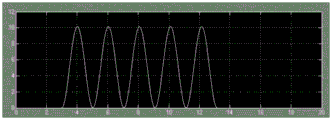
FIG. 4 is a schematic illustration of a waveform of the "1-cos" type applied in the present application.
Detailed Description
In order to make the purposes, technical solutions and advantages of the implementation of the present application more clear, the technical solutions in the embodiments of the present application will be described in more detail below with reference to the accompanying drawings in the embodiments of the present application.
In order to evaluate the rear limit of the center of gravity of the tail-free flying wing layout aircraft, the application provides a method for determining the rear limit of the center of gravity of the tail-free flying wing layout aircraft.
As shown in fig. 3, the method for determining the rear limit of the center of gravity of the tail-free flying wing layout aircraft of the application comprises the following steps:
s1, determining an initial gravity center rear limit of an arbitrary value;
s2, performing pneumatic control efficiency evaluation, actuator capacity evaluation, aircraft body stability evaluation, linear amplitude stability evaluation and nonlinear amplitude stability evaluation on the initial center of gravity rear limit;
s3, if any evaluation does not meet the requirement, advancing the initial barycenter rear limit until the barycenter rear limit can meet the evaluation requirement;
and S4, if the evaluation meets the requirements, shifting the initial gravity center rear limit backwards until the gravity center rear limit does not meet any of the evaluation requirements.
The specific processes of the pneumatic control efficiency evaluation, the actuator capability evaluation, the aircraft body stability evaluation, the linear amplitude stability evaluation and the nonlinear amplitude stability evaluation are as follows:
1. pneumatic steering efficiency assessment
Under the condition of maximum allowable attack angle range and gravity center rear limit, the airplane downward-depression control moment can prevent the attack angle of the airplane from diverging when the airplane rolls (stable axis roll angle rate)<=15°/s) and enables the aircraft to be quickly restored from the large angle of attack state to the small angle of attack state, the pitch acceleration generated by the dive restoring moment being not less than a predetermined value. In one embodiment of the present application, the predetermined pitch acceleration value is 0.4rad/s 2 。
The pitching acceleration generated by the pitching restoring moment can be obtained in the kinematic simulation model or the equation set under the condition of adjusting the gravity center rear limit.
2. Actuator capability assessment
The ability of the control surface to deflect at a rate and hinge moment within the flight envelope and under the aft limit of center of gravity should be sufficient to ensure safety over all attainable combinations of angles of attack and sideslip.
The above process can be obtained through simulation.
3. Aircraft body stability assessment
And under the conditions of the flight envelope and the allowable attack angle range and the rear limit of the center of gravity, the doubling time of the longitudinal short-period divergence of the aircraft body is not less than the first preset time, and the maximum doubling time of the transverse heading mode denominator transfer function divergence root of the body is not less than the second preset time. In an embodiment of the present application, the first predetermined time and the second predetermined time are both 400ms.
The process can be calculated by a kinematic mathematical model.
4. Linear stability assessment
Under the conditions of the flight envelope and the rear limit of the gravity center, the modal characteristics of the aircraft after stability augmentation should meet the requirements of relevant flight quality, and the stable reserve should meet the requirements of relevant flight quality, specifically as follows:
a) The pitching short period damping ratio and the frequency should meet the first-level flight quality requirement in the range of using the flight envelope, and at least meet the third-level flight quality (national army standard 185-86) requirement in the range of allowing the flight envelope;
b) The stable reserve of the pitching control stability augmentation loop meets the requirement that the amplitude reserve is larger than a preset value and the phase reserve is larger than a preset angle;
c) The Holland rolling modal damping ratio and the frequency meet the first-level flight quality requirement within the range of using the flight envelope; at least three-level flight quality requirements should be met within the allowable flight envelope;
d) The rolling modal time constant meets the first-level flight quality requirement in the range of using the flight envelope; at least three-level flight quality requirements should be met within the allowable flight envelope;
e) The stable reserve of the rolling yaw control stability augmentation loop should meet the requirement that the amplitude reserve is larger than a preset value and the phase reserve is larger than a preset angle;
in one embodiment of the present application, the amplitude reserve is predetermined to be + -6 dB and the phase reserve is predetermined to be 45 degrees.
The process can be calculated by a kinematic mathematical model.
5. Nonlinear stability assessment and assessment requirements
Under the conditions of the flight envelope and the rear limit of the gravity center, the aircraft after stability augmentation is added with a large-amplitude instruction or large-amplitude disturbance, and no divergent response is caused, specifically as follows:
a) At least 5 consecutive additions of "1-cos" type vertical full wave discrete gusts, see FIG. 4, should the aircraft not experience a divergence in response due to insufficient maneuvering performance;
b) Adding a normal overload instruction (amplitude takes the maximum normal overload value) in a sine form for at least 5 periods, wherein the aircraft should not cause response divergence due to insufficient maneuvering efficiency;
c) Continuously adding at least 5 times of 1-cos type lateral full-wave discrete gusts, wherein the aircraft should not cause response divergence due to insufficient maneuvering efficiency;
d) The aircraft should not experience a divergence in response due to insufficient maneuver performance by incorporating a roll angle rate command (magnitude taking the maximum roll angle rate value) in the form of a sine of at least 5 cycles.
The above process can be obtained through simulation.
Finally, in step S4, the shift granularity (or step size) of the center of gravity rear limit is 0.5.
The method for determining the tail-free flying wing layout aircraft gravity center rear limit can evaluate the gravity center rear limit according to the specificity of the tail-free flying wing layout aircraft, can comprehensively evaluate the operability, stability and flight safety of the aircraft under the gravity center rear limit, can determine the gravity center rear limit meeting the flight quality requirement, can guide the design of relevant parameters of the tail-free flying wing layout aircraft, and has extremely high engineering application value.
The foregoing is merely specific embodiments of the present application, but the scope of the present application is not limited thereto, and any changes or substitutions easily conceivable by those skilled in the art within the technical scope of the present application should be covered in the scope of the present application. Therefore, the protection scope of the present application shall be subject to the protection scope of the claims.
Claims (10)
1. A method for determining a rear limit of a center of gravity of a tailless flying wing layout aircraft, the method comprising:
determining an initial center of gravity rear limit of an arbitrary value;
performing pneumatic control efficiency evaluation, actuator capability evaluation, aircraft body stability evaluation, linear amplitude stability evaluation and nonlinear amplitude stability evaluation on the initial center of gravity rear limit;
if any of the above evaluations does not meet the requirements, advancing the initial barycenter rear limit until the barycenter rear limit meets the above evaluation requirements;
if the above-mentioned evaluation meets the requirements, then the initial barycenter rear limit is moved backward until the barycenter rear limit does not meet any of the above-mentioned evaluation requirements.
2. The method of determining a trailing free flying wing layout aircraft center of gravity rear limit according to claim 1, wherein the step of evaluating the initial center of gravity rear limit for aerodynamic performance comprises:
under the condition of the maximum allowable attack angle range and the gravity center rear limit, the airplane pitch-down control moment can prevent the divergence trend of the attack angle of the airplane during rolling, and can enable the airplane to recover from a larger attack angle state to a smaller attack angle state, and the pitch acceleration generated by the pitch-down recovery moment is not smaller than a preset value.
3. The method of determining the rear limit of the center of gravity of a tailless flying wing layout aircraft according to claim 2, wherein the predetermined value of pitch acceleration is 0.4rad/s 2 。
4. The method for determining the trailing edge of a tailless flying wing layout aircraft as defined in claim 1, wherein the step of evaluating the initial trailing edge of the center of gravity comprises:
under the conditions of the flight envelope and the rear limit of the gravity center, the deflection rate of the control surface and the moment of the hinge can ensure the flight safety in the combination range of all angles of attack and sideslip angles.
5. The method for determining the trailing edge of a tailless flying wing layout aircraft as defined in claim 1, wherein the step of evaluating the initial trailing edge of the center of gravity for aircraft body stability comprises:
and under the conditions of a flight envelope and an allowable attack angle range and a gravity center rear limit, the length doubling time of the longitudinal short-period divergence of the airplane body is not less than a first preset time, and the maximum length doubling time of the transverse heading mode denominator transfer function divergence root of the airplane body is not less than a second preset time.
6. The method of determining a rear limit of a center of gravity of a tailless flying wing layout aircraft according to claim 5, wherein the first predetermined time and the second predetermined time are each 400ms.
7. The method of determining a trailing-wing-free layout aircraft barycenter rear limit of claim 1, wherein the process of evaluating the initial barycenter rear limit for linear amplitude stability comprises:
under the conditions of the flight envelope and the rear limit of the center of gravity, the modal characteristics of the aircraft after stability augmentation can meet the following requirements:
a) The pitching short period damping ratio and the frequency meet the first-level flight quality requirement in the range of using the flight envelope, and at least meet the third-level flight quality requirement in the range of allowing the flight envelope;
b) The stable reserve of the pitching control stability augmentation loop meets the requirement that the amplitude reserve is larger than a preset value and the phase reserve is larger than a preset angle;
c) The Holland rolling modal damping ratio and the frequency meet the first-level flight quality requirement within the range of using the flight envelope; at least meeting the three-level flight quality requirements within the allowable flight envelope;
d) The rolling modal time constant meets the first-level flight quality requirement in the range of using the flight envelope; at least meeting the three-level flight quality requirements within the allowable flight envelope;
e) The stable reserve of the rolling yaw control stability augmentation loop meets the requirement that the amplitude reserve is larger than a preset value and the phase reserve is larger than a preset angle.
8. The method of determining the trailing edge of a tailless flying wing layout aircraft according to claim 7, wherein the predetermined value of the amplitude reserve is ± 6dB and the predetermined angle of the phase reserve is 45 degrees.
9. The method for determining the trailing edge of a tailless flying wing layout aircraft as defined in claim 1, wherein the step of evaluating the initial trailing edge of the center of gravity for nonlinear amplitude stability comprises:
under the conditions of the flight envelope and the rear limit of the gravity center, the aircraft after stability augmentation is added with a large-amplitude instruction or large-amplitude disturbance, and the following divergent response does not occur:
a) Continuously adding at least N periods of '1-cos' type vertical full-wave discrete gusts, wherein the aircraft does not cause response divergence due to insufficient maneuvering efficiency;
b) Adding normal overload instructions in a sine form for at least N periods, wherein the aircraft does not cause response divergence due to insufficient maneuvering efficiency;
c) Continuously adding at least N periods of '1-cos' type lateral full-wave discrete gusts, wherein the aircraft does not cause response divergence due to insufficient maneuvering efficiency;
d) The aircraft does not experience response divergence due to insufficient maneuver performance by incorporating roll angle rate commands in the form of at least 5 cycles of sinusoids.
10. The method for determining the trailing edge of the center of gravity of a tailless flying wing layout aircraft according to claim 1, wherein the moving granularity of the trailing edge of the center of gravity is 0.5.
Priority Applications (1)
| Application Number | Priority Date | Filing Date | Title |
|---|---|---|---|
| CN202110608229.3A CN113335552B (en) | 2021-06-01 | 2021-06-01 | Method for determining rear limit of gravity center of tail-free flying wing layout aircraft |
Applications Claiming Priority (1)
| Application Number | Priority Date | Filing Date | Title |
|---|---|---|---|
| CN202110608229.3A CN113335552B (en) | 2021-06-01 | 2021-06-01 | Method for determining rear limit of gravity center of tail-free flying wing layout aircraft |
Publications (2)
| Publication Number | Publication Date |
|---|---|
| CN113335552A CN113335552A (en) | 2021-09-03 |
| CN113335552B true CN113335552B (en) | 2023-07-07 |
Family
ID=77474105
Family Applications (1)
| Application Number | Title | Priority Date | Filing Date |
|---|---|---|---|
| CN202110608229.3A Active CN113335552B (en) | 2021-06-01 | 2021-06-01 | Method for determining rear limit of gravity center of tail-free flying wing layout aircraft |
Country Status (1)
| Country | Link |
|---|---|
| CN (1) | CN113335552B (en) |
Families Citing this family (1)
| Publication number | Priority date | Publication date | Assignee | Title |
|---|---|---|---|---|
| CN114154434B (en) * | 2021-11-18 | 2024-12-20 | 中国航空工业集团公司沈阳飞机设计研究所 | A multi-constrained refined aerodynamic optimization design method for tailless flying wing layout |
Citations (3)
| Publication number | Priority date | Publication date | Assignee | Title |
|---|---|---|---|---|
| CN103748587A (en) * | 2011-09-29 | 2014-04-23 | 三菱重工业株式会社 | Airplane design device, airplane design program, and airplane design method |
| CN104317996A (en) * | 2014-10-15 | 2015-01-28 | 中国航空工业集团公司沈阳飞机设计研究所 | Method for designing and evaluating center of gravity of airplane |
| CN109711008A (en) * | 2018-12-12 | 2019-05-03 | 南京航空航天大学 | A kind of center of gravity of airplane envelope curve calculation method |
Family Cites Families (3)
| Publication number | Priority date | Publication date | Assignee | Title |
|---|---|---|---|---|
| US7455264B2 (en) * | 1997-08-26 | 2008-11-25 | Mcdonnell Douglas Corporation | Reconfiguration control system for an aircraft wing |
| US8024079B2 (en) * | 2008-05-20 | 2011-09-20 | The Boeing Company | Wing-body load alleviation for aircraft |
| HUP1000048A2 (en) * | 2010-01-25 | 2011-11-28 | Nandor Vestroci | Wing arrangement for aircrafts |
-
2021
- 2021-06-01 CN CN202110608229.3A patent/CN113335552B/en active Active
Patent Citations (3)
| Publication number | Priority date | Publication date | Assignee | Title |
|---|---|---|---|---|
| CN103748587A (en) * | 2011-09-29 | 2014-04-23 | 三菱重工业株式会社 | Airplane design device, airplane design program, and airplane design method |
| CN104317996A (en) * | 2014-10-15 | 2015-01-28 | 中国航空工业集团公司沈阳飞机设计研究所 | Method for designing and evaluating center of gravity of airplane |
| CN109711008A (en) * | 2018-12-12 | 2019-05-03 | 南京航空航天大学 | A kind of center of gravity of airplane envelope curve calculation method |
Non-Patent Citations (1)
| Title |
|---|
| 翼身融合布局大型客机的重心分析;索欣诗等;航空计算技术;第47卷(第4期);第67-71页 * |
Also Published As
| Publication number | Publication date |
|---|---|
| CN113335552A (en) | 2021-09-03 |
Similar Documents
| Publication | Publication Date | Title |
|---|---|---|
| Theis et al. | Robust control design for active flutter suppression | |
| CN115793696B (en) | Hypersonic vehicle attitude control methods, systems, electronic equipment and media | |
| CN111306998A (en) | A parameter perturbation-adaptive vertical attack guidance method for guided rockets | |
| CN102707624B (en) | Design method of longitudinal controller region based on conventional aircraft model | |
| CN113335552B (en) | Method for determining rear limit of gravity center of tail-free flying wing layout aircraft | |
| CN112114522B (en) | Four-rotor aircraft fault tolerance control method based on switching adaptive algorithm | |
| CN116009594B (en) | A state-constrained fault-tolerant control method for hypersonic vehicles based on zero-sum game | |
| CN111007724A (en) | A Quantitative Tracking Control Method for Specified Performance of Hypersonic Aircraft Based on Interval Type II Fuzzy Neural Network | |
| CN118915813A (en) | Multi-index customization-oriented aviation aircraft performance-protecting control method | |
| Ye et al. | Heading control strategy assessment for coaxial compound helicopters | |
| CN106383523A (en) | Aircraft nonlinear attitude control system stability analysis method | |
| CN102692928B (en) | Controller region design method based on quaternion model of aircraft | |
| CN106569503A (en) | Triggering-type predictive control-based aircraft control method | |
| CN112947498A (en) | Aircraft track angle control method, system and storage medium | |
| CN102707629A (en) | Design method of full-dimensional controller region based on aircraft switching model | |
| Suresh Babu et al. | Leading-edge-vortex tailoring on unsteady airfoils using an inverse aerodynamic approach | |
| CN115097854A (en) | An attitude adaptive control method for fixed-wing UAV based on model correction | |
| CN102707722A (en) | Omni-dimensional controller area designing method based on normal aircraft model | |
| CN115327916B (en) | Adaptive compensation control method for aerodynamic parameter perturbation of high-mobility aircraft | |
| CN116400668B (en) | Aeroservoelastic characteristics evaluation method, device, equipment and storage medium | |
| CN110348081A (en) | Based on the fighter plane HAOA characteristics analysis method up to balance collection | |
| Ming et al. | Application of reinforcement learning in deep-stall recovery | |
| CN117369524A (en) | A high-altitude attitude stabilization control method for aircraft oriented to air rudder | |
| CN110109357A (en) | For half global self-adaptation control method of non-standard non-linear aircraft | |
| Zhang et al. | Stability analysis of flying wing layout aircraft based on radial basis function neural network model |
Legal Events
| Date | Code | Title | Description |
|---|---|---|---|
| PB01 | Publication | ||
| PB01 | Publication | ||
| SE01 | Entry into force of request for substantive examination | ||
| SE01 | Entry into force of request for substantive examination | ||
| GR01 | Patent grant | ||
| GR01 | Patent grant |