CN113321350A - Chemical fiber production sewage comprehensive treatment device - Google Patents
Chemical fiber production sewage comprehensive treatment device Download PDFInfo
- Publication number
- CN113321350A CN113321350A CN202110803307.5A CN202110803307A CN113321350A CN 113321350 A CN113321350 A CN 113321350A CN 202110803307 A CN202110803307 A CN 202110803307A CN 113321350 A CN113321350 A CN 113321350A
- Authority
- CN
- China
- Prior art keywords
- shaped
- frame
- special
- reaction tank
- chemical fiber
- Prior art date
- Legal status (The legal status is an assumption and is not a legal conclusion. Google has not performed a legal analysis and makes no representation as to the accuracy of the status listed.)
- Pending
Links
Images


Classifications
-
- C—CHEMISTRY; METALLURGY
- C02—TREATMENT OF WATER, WASTE WATER, SEWAGE, OR SLUDGE
- C02F—TREATMENT OF WATER, WASTE WATER, SEWAGE, OR SLUDGE
- C02F9/00—Multistage treatment of water, waste water or sewage
-
- C—CHEMISTRY; METALLURGY
- C02—TREATMENT OF WATER, WASTE WATER, SEWAGE, OR SLUDGE
- C02F—TREATMENT OF WATER, WASTE WATER, SEWAGE, OR SLUDGE
- C02F1/00—Treatment of water, waste water, or sewage
- C02F1/001—Processes for the treatment of water whereby the filtration technique is of importance
-
- C—CHEMISTRY; METALLURGY
- C02—TREATMENT OF WATER, WASTE WATER, SEWAGE, OR SLUDGE
- C02F—TREATMENT OF WATER, WASTE WATER, SEWAGE, OR SLUDGE
- C02F1/00—Treatment of water, waste water, or sewage
- C02F1/28—Treatment of water, waste water, or sewage by sorption
- C02F1/283—Treatment of water, waste water, or sewage by sorption using coal, charred products, or inorganic mixtures containing them
-
- C—CHEMISTRY; METALLURGY
- C02—TREATMENT OF WATER, WASTE WATER, SEWAGE, OR SLUDGE
- C02F—TREATMENT OF WATER, WASTE WATER, SEWAGE, OR SLUDGE
- C02F1/00—Treatment of water, waste water, or sewage
- C02F1/38—Treatment of water, waste water, or sewage by centrifugal separation
-
- C—CHEMISTRY; METALLURGY
- C02—TREATMENT OF WATER, WASTE WATER, SEWAGE, OR SLUDGE
- C02F—TREATMENT OF WATER, WASTE WATER, SEWAGE, OR SLUDGE
- C02F1/00—Treatment of water, waste water, or sewage
- C02F1/40—Devices for separating or removing fatty or oily substances or similar floating material
-
- C—CHEMISTRY; METALLURGY
- C02—TREATMENT OF WATER, WASTE WATER, SEWAGE, OR SLUDGE
- C02F—TREATMENT OF WATER, WASTE WATER, SEWAGE, OR SLUDGE
- C02F1/00—Treatment of water, waste water, or sewage
- C02F1/50—Treatment of water, waste water, or sewage by addition or application of a germicide or by oligodynamic treatment
-
- C—CHEMISTRY; METALLURGY
- C02—TREATMENT OF WATER, WASTE WATER, SEWAGE, OR SLUDGE
- C02F—TREATMENT OF WATER, WASTE WATER, SEWAGE, OR SLUDGE
- C02F2101/00—Nature of the contaminant
- C02F2101/10—Inorganic compounds
- C02F2101/12—Halogens or halogen-containing compounds
-
- C—CHEMISTRY; METALLURGY
- C02—TREATMENT OF WATER, WASTE WATER, SEWAGE, OR SLUDGE
- C02F—TREATMENT OF WATER, WASTE WATER, SEWAGE, OR SLUDGE
- C02F2101/00—Nature of the contaminant
- C02F2101/30—Organic compounds
-
- C—CHEMISTRY; METALLURGY
- C02—TREATMENT OF WATER, WASTE WATER, SEWAGE, OR SLUDGE
- C02F—TREATMENT OF WATER, WASTE WATER, SEWAGE, OR SLUDGE
- C02F2101/00—Nature of the contaminant
- C02F2101/30—Organic compounds
- C02F2101/36—Organic compounds containing halogen
-
- C—CHEMISTRY; METALLURGY
- C02—TREATMENT OF WATER, WASTE WATER, SEWAGE, OR SLUDGE
- C02F—TREATMENT OF WATER, WASTE WATER, SEWAGE, OR SLUDGE
- C02F2103/00—Nature of the water, waste water, sewage or sludge to be treated
- C02F2103/30—Nature of the water, waste water, sewage or sludge to be treated from the textile industry
-
- C—CHEMISTRY; METALLURGY
- C02—TREATMENT OF WATER, WASTE WATER, SEWAGE, OR SLUDGE
- C02F—TREATMENT OF WATER, WASTE WATER, SEWAGE, OR SLUDGE
- C02F2103/00—Nature of the water, waste water, sewage or sludge to be treated
- C02F2103/34—Nature of the water, waste water, sewage or sludge to be treated from industrial activities not provided for in groups C02F2103/12 - C02F2103/32
- C02F2103/36—Nature of the water, waste water, sewage or sludge to be treated from industrial activities not provided for in groups C02F2103/12 - C02F2103/32 from the manufacture of organic compounds
- C02F2103/38—Polymers
Landscapes
- Life Sciences & Earth Sciences (AREA)
- Hydrology & Water Resources (AREA)
- Engineering & Computer Science (AREA)
- Environmental & Geological Engineering (AREA)
- Water Supply & Treatment (AREA)
- Chemical & Material Sciences (AREA)
- Organic Chemistry (AREA)
- Treatment Of Water By Oxidation Or Reduction (AREA)
Abstract
The invention relates to the field of chemical sewage treatment, in particular to a chemical fiber production sewage comprehensive treatment device, which comprises a fixed base, a special-shaped water injection pipe, a reaction tank, a switching-off mechanism and the like; the fixed base upper left side fixed mounting has heterotypic water injection pipe, and fixed base top fixed connection has the reaction tank, and the reaction tank is inside to be the cavity structure, and the reaction tank is located heterotypic water injection pipe right side, is equipped with the mechanism of opening floodgate on the reaction tank. Through the cooperation of filter plate one, filter plate two and carbon filter branch sieve layer, filter plate one can carry out the prefilter to chemical fiber production sewage with filter plate two to get rid of most suspended solid, particulate matter etc. in the chemical fiber production sewage, carbon filter divides the sieve layer can adsorb organic matter and chlorine residue etc. in the chemical fiber production sewage, thereby can further get rid of the impurity in the chemical fiber production sewage, has reached the effect that can get rid of the impurity in the chemical fiber production sewage effectively.
Description
Technical Field
The invention relates to the field of chemical sewage treatment, in particular to a chemical fiber production sewage comprehensive treatment device.
Background
The chemical fiber is a fiber with textile property, which is prepared by using a natural high molecular compound or an artificially synthesized high molecular compound as a raw material and through the procedures of preparing a spinning solution, spinning, post-treatment and the like, the fiber can meet the requirements of textile processing and use only through a series of post-processing, and the processing aims at improving the mechanical property and the dimensional stability of the fiber. Chemical fiber fabrics are novel clothing materials developed recently, the types of the chemical fiber fabrics are more, and the market of chemical fibers is gradually expanded along with the development of science and technology.
Because chemical fiber production factory can produce all kinds of sewage in the chemical fiber production process, its sewage composition is complicated, often contain strong acid, alkali, cellulose etc. and various toxic substances, if directly discharge chemical fiber production sewage, easily produce the toxic effect to the microorganism, can the polluted environment simultaneously and cause very big harm to human health, consequently need handle chemical fiber production sewage, change the harm into the benefit, can discharge after taking corresponding purification measure to dispose, in order to reach the purpose of water economy resource and environmental protection, and current equipment is when carrying out purification treatment to it, the efficiency of processing is lower, and difficult oil separating in the chemical fiber production sewage.
Disclosure of Invention
Based on this, it is necessary to provide a comprehensive treatment device for chemical fiber production wastewater, which can effectively remove impurities in the chemical fiber production wastewater, can automatically add sodium hypochlorite to inactivate bacteria in the chemical fiber production wastewater, has high treatment efficiency, and can automatically separate oil from the chemical fiber production wastewater, so as to solve the problems that the direct discharge of the chemical fiber production wastewater in the background art easily causes toxic action on microorganisms, the chemical fiber production wastewater pollutes the environment, and the harm to human health is great.
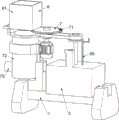
The technical scheme is as follows: chemical fiber production sewage integrated processing device, including unable adjustment base, abnormal shape water injection pipe, reaction tank, switching-off mechanism and rabbling mechanism: the special-shaped water injection pipe is fixedly arranged above the left side of the fixed base and is used for conveying sewage generated in the production of chemical fibers; the reaction tank is fixedly connected above the fixed base, the interior of the reaction tank is of a cavity structure, the reaction tank is positioned on the right side of the special-shaped water injection pipe, and the reaction tank is used for providing a closed space required for treating chemical fiber production sewage; the opening mechanism is arranged on the reaction tank and used for controlling the input and discharge of the chemical fiber production sewage in the reaction tank; the stirring mechanism is arranged above the special-shaped water injection pipe and used for fully stirring the chemical fiber production sewage in the reaction tank 3 and the sodium hypochlorite, and the effect of accelerating the reaction rate of the chemical fiber production sewage in the reaction tank 3 is achieved.
In addition, particularly preferably, the brake opening mechanism comprises a short valve body, an L-shaped slide rail frame, a first butterfly valve, a first gear, a special-shaped slide rack frame, a first reset spring, a long valve body and a second butterfly valve, wherein the short valve body is jointly connected between the special-shaped water injection pipe and the reaction tank, the short valve body is respectively communicated with the special-shaped water injection pipe and the reaction tank, the L-shaped slide rail frame is connected to the left side of the outer wall of the reaction tank, the first butterfly valve is rotatably connected to the inside of the short valve body, the first gear is fixedly connected to the upper side of the first butterfly valve, the first gear is positioned above the short valve body, the special-shaped slide rack frame is slidably connected to the L-shaped slide rail frame, the special-shaped slide rack frame is positioned at the front side of the first gear and is meshed with the first gear, the first reset spring is connected between the special-shaped slide rack frame and the L-shaped slide rail frame, the long valve body is connected to the right side of the outer wall of the reaction tank, the long valve body is communicated with the reaction tank, the second butterfly valve is rotatably connected to the inside of the long valve body, a first gear is also connected to the upper portion of the second butterfly valve and is meshed with the special-shaped sliding rack.
In addition, particularly preferably, the stirring mechanism comprises a motor support ring, a servo motor, a short shaft, a first belt pulley, a special-shaped rotating frame, a second belt pulley, a perforated shaft, a conveying belt, a long shaft, stirring blades, a clamping rod and a second return spring, wherein the motor support ring is fixedly connected above the special-shaped water injection pipe, the servo motor is installed on the right side of the motor support ring, the short shaft is fixedly connected to an output shaft of the servo motor, the first belt pulley is fixedly connected to the short shaft, the special-shaped rotating frame is fixedly connected to the upper part of the reaction tank, the second belt pulley is rotatably connected to the upper part of the special-shaped rotating frame, the perforated shaft penetrates through the second belt pulley, the conveying belt is wound between the second belt pulley and the first belt pulley, the long shaft is fixedly connected to the lower part of the perforated shaft, the long shaft is rotatably connected, the clamping rod is clamped on the hole-opening shaft, and a second reset spring is connected between the clamping rod and the second belt pulley.
In addition, it is especially preferred that the device further comprises a deoiling mechanism, the deoiling mechanism is arranged on the motor support ring, the deoiling mechanism comprises a second gear, a special-shaped perforated pipe, a third gear, a perforated rotary cylinder and a filtered oil pipe, the second gear is fixedly connected to the short shaft, the special-shaped perforated pipe is fixedly connected to the motor support ring, the perforated rotary cylinder is rotatably connected to the inside of the special-shaped perforated pipe, the third gear is connected to the upper portion of the perforated rotary cylinder and meshed with the second gear, the third gear is located on the left side of the second gear, the filtered oil pipe is fixedly connected to the inside of the perforated rotary cylinder, and the filtered oil pipe penetrates through the special-shaped perforated pipe.
In addition, especially preferred is, still including sand filtering mechanism, sand filtering mechanism locates heterotypic trompil pipe top, and sand filtering mechanism is including rectangle filter frame, filter plate one and filter plate two, and rectangle filter frame fixed connection is in heterotypic trompil pipe top, and rectangle filter frame is connected with trompil rotary drum rotary type, and upper portion fixedly connected with filter plate one in the rectangle filter frame, lower part fixedly connected with filter plate two in the rectangle filter frame.
In addition, it is especially preferred that the push-down mechanism is further included, the push-down mechanism is arranged on the special-shaped rotating frame and comprises a cam, a T-shaped push rod, a third reset spring, a pushing wedge block and a fourth reset spring, the cam is fixedly connected to the upper portion of the long shaft, the T-shaped push rod is connected to the upper portion of the special-shaped rotating frame in a sliding mode, the T-shaped push rod is in contact with the cam, the third reset spring is connected between the T-shaped push rod and the special-shaped rotating frame, the pushing wedge block is connected to the T-shaped push rod in a sliding mode, and the fourth reset spring is connected between the pushing wedge block and the T-shaped push rod.
In addition, it is especially preferred that the special-shaped drilling machine further comprises a speed reducing mechanism, wherein the speed reducing mechanism is partially arranged on the special-shaped rotating frame and comprises a special-shaped drilling frame, clamping beads and a fifth return spring, the right side of the special-shaped rotating frame is fixedly connected with the three-different-shaped drilling frame in a linear distributed mode, the clamping beads are connected onto the special-shaped drilling frame in a sliding mode, and the fifth return spring is connected between the clamping beads and the special-shaped drilling frame.
In addition, particularly preferably, the device also comprises a reset mechanism, the reset mechanism is commonly arranged between the three-differential slotted frames, the reset mechanism comprises a rectangular slide rail frame, a special-shaped lower slide bar, a sixth reset spring, a special-shaped slotted frame, a wedge-shaped limit frame I, a seventh reset spring, an L-shaped slotted frame, a limit wedge-shaped frame II and an eighth reset spring, the rectangular slide rail frame is fixedly connected between the three-differential slotted frames, the special-shaped lower slide bar is connected with the rectangular slide rail frame in a sliding way, the special-shaped lower slide bar is contacted with a pushing wedge-shaped block, a clamping ball is clamped into the left side of the special-shaped lower slide bar, the sixth reset spring is connected between the special-shaped lower slide bar and the rectangular slide rail frame, the special-shaped slotted frame is fixedly connected below the right side of the rectangular slide rail frame, the wedge-shaped limit frame I is connected with the special-shaped lower slide bar in a sliding way, the wedge-shaped limit frame I is contacted with the special-shaped lower slide bar, the seventh reset spring is connected between the wedge-shaped limit frame I and the special-shaped slotted frame, the rear side of the rectangular slide rail frame is fixedly connected with an L-shaped slotting frame, the L-shaped slotting frame is connected with a second limiting wedge-shaped frame in a sliding mode, and an eighth reset spring is connected between the second limiting wedge-shaped frame and the L-shaped slotting frame.
In addition, it is especially preferred, still including medicine mechanism, reaction tank top is located to medicine mechanism, medicine mechanism is including cowl, a rubber medicament section of thick bamboo, L type mount, the lifter, ninth reset spring, swing wedge and torque spring, reaction tank top fixedly connected with cowl, rubber medicament section of thick bamboo has been cup jointed to the reaction tank top, cowl and rubber medicament section of thick bamboo contact, fixedly connected with L type mount on the reaction tank, the gliding style is connected with the lifter on the L type mount, be connected with ninth reset spring between lifter and the L type mount, the gliding style is connected with the swing wedge on the lifter, swing wedge and lifter contact, the symmetric connection has torque spring between swing wedge and the lifter.
In addition, especially preferred is, still including carbon and strain the branch sieve layer, and the fixed baseplate right side fixed mounting has carbon to strain the branch sieve layer, and carbon is strained and is divided sieve layer and long valve body intercommunication.
Compared with the prior art, the invention has the following advantages:
through stirring fan blade and the cooperation of device on it, stirring fan blade can stir chemical fiber production sewage and sodium hypochlorite in the reaction tank fully to make chemical fiber production sewage in the reaction tank and sodium hypochlorite misce bene in order to accelerate its reaction rate, be favorable to handling chemical fiber production sewage, reached the purpose that can improve chemical fiber production sewage's processing rate effectively.
Through the cooperation of filter plate one, filter plate two and carbon filter branch sieve layer, filter plate one can carry out the prefilter to chemical fiber production sewage with filter plate two to get rid of most suspended solid, particulate matter etc. in the chemical fiber production sewage, carbon filter divides the sieve layer can adsorb organic matter and chlorine residue etc. in the chemical fiber production sewage, thereby can further get rid of the impurity in the chemical fiber production sewage, has reached the effect that can get rid of the impurity in the chemical fiber production sewage effectively.
Through the cooperation of the rotary drum with the opening and the device thereon, the rotary drum with the opening and the device thereon rotate at a high speed to separate oil and water in the chemical fiber production sewage and discharge the oil and the water respectively, so that the chemical fiber production sewage is treated subsequently, and the effect of automatically separating the oil in the chemical fiber production sewage is achieved.
Through the cooperation of the extrusion stem and the rubber medicament barrel and the device above, the extrusion stem can extrude the rubber medicament barrel and make its inside sodium hypochlorite pour into the reaction tank inside, and the bacterium in the chemical fiber production sewage can be inactivated rapidly to the sodium hypochlorite to handle chemical fiber production sewage, reached and to have added the effect of the bacterium in the sodium hypochlorite with the inactivation chemical fiber production sewage automatically.
Drawings
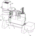
Fig. 1 is a schematic perspective view of a first embodiment of the present invention.
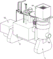
Fig. 2 is a schematic perspective view of a second embodiment of the present invention.
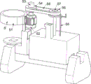
Fig. 3 is a partial perspective view of the present invention.
FIG. 4 is a schematic diagram of a first partially-separated body structure of the opening mechanism of the present invention.
FIG. 5 is a schematic diagram of a second partial structure of the opening mechanism of the present invention.
Fig. 6 is a perspective view of a third part of the switching-off mechanism of the present invention.
FIG. 7 is a schematic view of a first partial body structure of the stirring mechanism of the present invention.
FIG. 8 is a schematic view of a second partial body structure of the stirring mechanism of the present invention.
Fig. 9 is a partially disassembled perspective view of the stirring mechanism of the present invention.
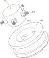
Fig. 10 is a schematic perspective view of a part of the deoiling mechanism of the present invention.
Fig. 11 is a schematic sectional perspective view of the sand filter mechanism of the present invention.
Fig. 12 is a schematic perspective view of a portion of the pressing mechanism of the present invention.
Fig. 13 is a schematic disassembled perspective view of the speed reducing mechanism of the present invention.
Fig. 14 is a partially disassembled perspective view of the pressing mechanism of the present invention.
Fig. 15 is a schematic perspective view of the reset mechanism of the present invention.
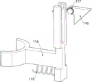
FIG. 16 is a schematic view of a partial perspective structure of the medicated mechanism of the present invention.
Fig. 17 is a partially-disassembled three-dimensional structure schematic diagram of the medicine adding mechanism.
In the figure: 1. a fixed base, 2, a special-shaped water injection pipe, 3, a reaction tank, 4, a switching-off mechanism, 41, a short valve body, 42, an L-shaped slide rail frame, 43, a first butterfly valve, 44, a first gear, 45, a special-shaped slide rack frame, 46, a first return spring, 47, a long valve body, 48, a second butterfly valve, 5, a stirring mechanism, 51, a motor support ring, 52, a servo motor, 53, a short shaft, 54, a first belt pulley, 55, a special-shaped rotating frame, 56, a second belt pulley, 57, a hole opening shaft, 58, a conveying belt, 59, a long shaft, 510, a stirring fan blade, 511, a clamping rod, 512, a second return spring, 6, a sand filtering mechanism, 61, a rectangular filter frame, 62, a first filter plate, 63, a second filter plate, 7, an oil removing mechanism, 71, a second gear, 72, a special-shaped hole opening pipe, 73, a third gear, 74, a hole opening rotating cylinder, 75, a filter oil pipe, 8, a pressing mechanism, 81, a cam, 82 and a T-shaped pushing rod, 83. the device comprises a third return spring, 84, a pushing wedge block, 85, a fourth return spring, 9, a speed reducing mechanism, 91, a special-shaped slotted frame, 92, a clamping bead, 93, a fifth return spring, 10, a return mechanism, 101, a rectangular slide rail frame, 102, a special-shaped lower slide rod, 103, a sixth return spring, 104, a special-shaped slotted frame, 105, a first wedge-shaped limiting frame, 106, a seventh return spring, 107, an L-shaped slotted frame, 108, a second limiting wedge-shaped frame, 109, an eighth return spring, 11, a medicine adding mechanism, 111, an arc baffle, 112, a rubber medicine barrel, 113, an L-shaped fixing frame, 114, an extrusion rod, 115, a ninth return spring, 116, a swinging wedge block, 117, a torsion spring, 12 and a carbon filtering and screening layer.
Detailed Description
The standard parts used in the invention can be purchased from the market, the special-shaped parts can be customized according to the description and the description of the attached drawings, and the specific connection mode of each part adopts the conventional means of mature bolts, rivets, welding, sticking and the like in the prior art, and the detailed description is not repeated.
Example 1
Chemical fiber production sewage integrated processing device, as shown in fig. 1-9, including unable adjustment base 1, abnormal shape water injection pipe 2, reaction tank 3, switching-off mechanism 4 and rabbling mechanism 5, unable adjustment base 1 upper left side fixed mounting has abnormal shape water injection pipe 2 that is used for carrying chemical fiber production sewage, unable adjustment base 1 top fixed connection has reaction tank 3, reaction tank 3 is inside to be the cavity structure, reaction tank 3 is located abnormal shape water injection pipe 2 right side, be equipped with the transport switching-off mechanism 4 that is used for controlling chemical fiber production sewage on the reaction tank 3, abnormal shape water injection pipe 2 top is equipped with the rabbling mechanism 5 that is used for fully stirring chemical fiber production sewage and sodium hypochlorite in the reaction tank 3.
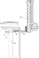
The brake opening mechanism 4 comprises a short valve body 41, an L-shaped sliding rail frame 42, a first butterfly valve 43, a first gear 44, a special-shaped sliding rack frame 45, a first reset spring 46, a long valve body 47 and a second butterfly valve 48, wherein the short valve body 41 is jointly connected between the special-shaped water injection pipe 2 and the reaction tank 3, the interior of the short valve body 41 is of a cavity structure, the short valve body 41 is communicated with the special-shaped water injection pipe 2 and the reaction tank 3, the L-shaped sliding rail frame 42 is connected to the left side of the outer wall of the reaction tank 3, the first butterfly valve 43 is rotatably connected to the interior of the short valve body 41, the lower part of the first butterfly valve 43 is of a disc structure, the first gear 44 is fixedly connected to the upper part of the first butterfly valve 43, the first gear 44 is located above the short valve body 41, the special-shaped sliding rack frame 45 is slidably connected to the L-shaped sliding rail frame 42, the special-shaped sliding rack frame 45 is located at the front side of the first gear 44, the special-shaped sliding rack frame 45 is meshed with the first gear 44, the first reset spring 46 for driving the special-shaped sliding rack frame 45 to reset is connected between the special-shaped sliding rack frame 42, the right side of the outer wall of the reaction tank 3 is connected with a long valve body 47, the long valve body 47 is positioned at the right lower part of the short valve body 41, the long valve body 47 is communicated with the reaction tank 3, the inner part of the long valve body 47 is rotatably connected with a second butterfly valve 48, the lower part of the second butterfly valve 48 is also in a disc structure, the upper part of the second butterfly valve 48 is also connected with a first gear 44, and the first gear 44 is also meshed with the special-shaped sliding rack 45.
The stirring mechanism 5 comprises a motor support ring 51, a servo motor 52, a short shaft 53, a first belt pulley 54, a special-shaped rotating frame 55, a second belt pulley 56, a hole opening shaft 57, a conveying belt 58, a long shaft 59, stirring fan blades 510, a clamping rod 511 and a second reset spring 512, the motor support ring 51 is fixedly connected above the special-shaped water injection pipe 2, the left side of the upper part of the motor support ring 51 is of a circular ring structure, the servo motor 52 is installed on the right side of the motor support ring 51, the short shaft 53 is fixedly connected to an output shaft of the servo motor 52, the first belt pulley 54 is fixedly connected to the short shaft 53, the first belt pulley 54 is positioned above the servo motor 52, the special-shaped rotating frame 55 is fixedly connected above the reaction tank 3, the left side of the upper part of the special-shaped rotating frame 55 is of a circular ring structure, the special-shaped rotating frame 55 is positioned on the right side of the motor support ring 51, the second belt pulley 56 is rotatably connected above the special-shaped rotating frame 55, and the second belt pulley 56 is positioned on the right side of the first belt pulley 54, the second belt pulley 56 is internally penetrated with a hole-opening shaft 57, a conveying belt 58 is wound between the second belt pulley 56 and the first belt pulley 54, a long shaft 59 is fixedly connected below the hole-opening shaft 57, the long shaft 59 is rotatably connected with the reaction tank 3, a pair of stirring fan blades 510 used for fully stirring chemical fiber production sewage and sodium hypochlorite in the reaction tank 3 are connected to the long shaft 59, the stirring fan blades 510 are positioned inside the reaction tank 3, four clamping rods 511 are circumferentially distributed and slidably connected in the second belt pulley 56, the clamping rods 511 are clamped on the hole-opening shaft 57, and a second reset spring 512 used for driving the clamping rods 511 to reset is connected between the clamping rods 511 and the second belt pulley 56.
The special-shaped sliding rack 45 is manually pushed to move rightwards, the special-shaped sliding rack 45 drives the first two gears 44 and the upper devices thereof to rotate and enables the first butterfly valve 43 and the second butterfly valve 48 to be opened, then chemical fiber production sewage is injected into the reaction tank 3 through the special-shaped water injection pipe 2 and the short valve body 41 by using other water injection equipment, then the special-shaped sliding rack 45 is loosened and drives the first two gears 44 and the upper devices thereof to reset, so that the first butterfly valve 43 and the second butterfly valve 48 are closed, then sodium hypochlorite is manually added into the reaction tank 3, then the servo motor 52 is manually controlled to be started, so that the short shaft 53 and the upper devices thereof rotate, the first belt pulley 54 drives the second belt pulley 56 and the upper devices thereof to rotate through the conveying belt 58, the long shaft 59 and the upper devices thereof also rotate through the matching of the clamping rod 511 and the second reset spring 512, and the stirring fan blades 510 are enabled to fully stir the chemical fiber production sewage and the sodium hypochlorite in the reaction tank 3, and then make chemical fiber production sewage in the reaction tank 3 and sodium hypochlorite misce bene in order to accelerate its reaction rate, handle the back and control servo motor 52 and close after accomplishing, then open butterfly valve II 48 again and make the chemical fiber production sewage after the processing discharge through long valve body 47.
Example 2
On the basis of the embodiment 1, as shown in fig. 10-11, the oil removing mechanism 7 is further included, the oil removing mechanism 7 is arranged on the motor supporting ring 51, the deoiling mechanism 7 for separating oil from water in the chemical fiber production sewage comprises a second gear 71, a special-shaped perforated pipe 72, a third gear 73, a perforated rotary drum 74 and a filtering oil pipe 75, the second gear 71 is fixedly connected to the short shaft 53, the special-shaped perforated pipe 72 is fixedly connected to the motor support ring 51, the perforated rotary drum 74 is rotatably connected to the inside of the special-shaped perforated pipe 72, the perforated rotary drum 74 is cylindrical, the lower portion of the perforated rotary drum 74 is conical, the perforated rotary drum 74 is located inside the special-shaped perforated pipe 72, the third gear 73 is connected to the upper portion of the perforated rotary drum 74, the third gear 73 is meshed with the second gear 71, the third gear 73 is located on the left side of the second gear 71, the filtering oil pipe 75 is fixedly connected to the inside of the perforated rotary drum 74, and the filtering oil pipe 75 penetrates through the special-shaped perforated pipe 72.
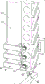
Still including sand filtering mechanism 6, a sand filtering mechanism 6 for getting rid of suspended solid and particulate matter etc. in the chemical fiber production sewage locates heterotypic trompil pipe 72 top, sand filtering mechanism 6 is including rectangle filter frame 61, filter plate one 62 and two 63 of filter plate, rectangle filter frame 61 fixed connection is in heterotypic trompil pipe 72 top, rectangle filter frame 61 is connected with trompil rotary drum 74 rotary type, upper portion fixedly connected with filter plate one 62 in the rectangle filter frame 61, lower part fixedly connected with filter plate two 63 in the rectangle filter frame 61, filter plate two 63 are located filter plate one 62 below, filter plate one 62 all is used for filtering chemical fiber production sewage with filter plate two 63.
The chemical fiber production sewage is injected onto the rectangular filter frame 61 by using other water injection equipment, the chemical fiber production sewage filtered by the filter plates 62 and 63 can flow into the perforated rotary cylinder 74, suspended matters, particles and the like in the chemical fiber production sewage can be removed due to the filtering action of the filter plates 62 and 63, when the gear wheel 71 and the device on the gear wheel rotate, the gear wheel 73 and the device on the gear wheel can be driven to rotate at a high speed, the oil and the water in the chemical fiber production sewage are separated by the high-speed rotation due to the different densities of the oil and the water in the chemical fiber production sewage, the oil in the chemical fiber production sewage can be discharged onto other equipment through the perforated rotary cylinder 75, and the water in the chemical fiber production sewage can flow into the special-shaped perforated pipe 72 through the small holes in the perforated rotary cylinder 74 and flow into the reaction tank 3 through the special-shaped water injection pipe 2 and the short valve body 41.
Example 3
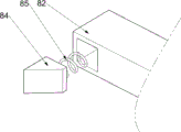
On the basis of the embodiment 2, as shown in fig. 12 to 15, the pressing mechanism 8 is further included, the pressing mechanism 8 is disposed on the special-shaped rotating frame 55, the pressing mechanism 8 includes a cam 81, a T-shaped pushing rod 82, a third return spring 83, a pushing wedge 84 and a fourth return spring 85, the cam 81 is fixedly connected to the upper portion of the long shaft 59, the T-shaped pushing rod 82 is slidably connected to the upper portion of the special-shaped rotating frame 55, the T-shaped pushing rod 82 is located on the right side of the cam 81, the T-shaped pushing rod 82 is in contact with the cam 81, the third return spring 83 for driving the T-shaped pushing rod 82 to return is connected between the T-shaped pushing rod 82 and the special-shaped rotating frame 55, the pushing wedge 84 is slidably connected to the T-shaped pushing rod 82, and the fourth return spring 85 for driving the pushing wedge 84 to return is connected between the pushing wedge 84 and the T-shaped pushing rod 82.
The chemical fiber production sewage treatment device is characterized by further comprising a speed reducing mechanism 9, wherein the speed reducing mechanism 9 for enabling chemical fiber production sewage treated in the reaction tank 3 to be drained to the greatest extent is arranged on the special-shaped rotating frame 55, the speed reducing mechanism 9 comprises a special-shaped open hole frame 91, clamping beads 92 and a fifth reset spring 93, the right side of the special-shaped rotating frame 55 is fixedly connected with the three-shaped open hole frame 91 in a linear distributed mode, the clamping beads 92 are slidably connected onto the special-shaped open hole frame 91, the right side of the clamping beads 92 is in a spherical shape, and the fifth reset spring 93 for driving the clamping beads 92 to reset is connected between the clamping beads 92 and the special-shaped open hole frame 91.
The special-shaped lower slide bar pushing device further comprises a reset mechanism 10, the reset mechanism 10 is arranged between the three-different-shaped slotted frames 91, the reset mechanism 10 comprises a rectangular slide rail frame 101, a special-shaped lower slide bar 102, a sixth reset spring 103, a special-shaped slotted frame 104, a wedge-shaped limit frame I105, a seventh reset spring 106, an L-shaped slotted frame 107, a limit wedge-shaped frame II 108 and an eighth reset spring 109, the rectangular slide rail frame 101 is fixedly connected between the three-different-shaped slotted frames 91, the special-shaped lower slide bar 102 is connected on the rectangular slide rail frame 101 in a sliding mode, oblique strip-shaped bars are arranged on the front side of the special-shaped lower slide bar 102 in a linear distribution mode, the special-shaped lower slide bar 102 is in contact with the pushing wedge-shaped block 84, the clamp ball 92 is clamped on the left side of the special-shaped lower slide bar 102, the sixth reset spring 103 used for driving the special-shaped lower slide bar 102 to reset is connected between the special-shaped lower slide rail frame 101, the special-shaped slotted frame 104 is fixedly connected below the right side of the rectangular slide rail frame 101, the special-shaped slotting machine is characterized in that a wedge-shaped limiting frame I105 is connected to the special-shaped slotting frame 104 in a sliding mode, both ends of the wedge-shaped limiting frame I105 are of inclined surface structures, the wedge-shaped limiting frame I105 is in contact with the special-shaped lower sliding rod 102, a seventh reset spring 106 used for driving the wedge-shaped limiting frame I105 to reset is connected between the wedge-shaped limiting frame I105 and the special-shaped slotting frame 104, an L-shaped slotting frame 107 is fixedly connected to the rear side of the rectangular sliding rail frame 101, a limiting wedge-shaped frame II 108 is connected to the L-shaped slotting frame 107 in a sliding mode, both ends of the limiting wedge-shaped frame II 108 are of inclined surface structures, and an eighth reset spring 109 used for driving the limiting wedge-shaped frame II 108 to reset is connected between the limiting wedge-shaped slotting frame II 108 and the L-shaped slotting frame 107.
In the process of rotating the long shaft 59 and the device thereon, the cam 81 drives the T-shaped push rod 82 and the device thereon to reciprocate left and right through the cooperation of the cam 81, the T-shaped push rod 82 and the device thereon, the wedge 84 is pushed to intermittently drive the special-shaped lower sliding rod 102 to move downwards through the cooperation of the wedge 84 and the fourth return spring 85, the sixth return spring 103 is compressed, the special-shaped lower sliding rod 102 can be clamped and prevented from resetting through the cooperation of the wedge-shaped first limiting frame 105 and the seventh return spring 106 in the process, the wedge-shaped first limiting frame 105 can clamp the special-shaped lower sliding rod 102, when the special-shaped lower sliding rod 102 moves downwards, the special-shaped lower sliding rod 102 is separated from the second limiting wedge-shaped frame 108, the special-shaped lower sliding rod 102 does not push against the second limiting wedge-shaped frame 108 any more, the stretched eighth return spring 109 can recover and drive the second limiting wedge-shaped frame 108 to move forwards, and then the special-shaped lower sliding rod 102 is contacted with the first wedge-shaped limiting frame 105, the profiled lower slide bar 102 will push the wedge-shaped first stop 105 and the upper device to move to the right, the seventh return spring 106 will be stretched accordingly, so that the first wedge-shaped limiting frame 105 no longer blocks the special-shaped lower sliding rod 102, the sixth return spring 103 will return and drive the special-shaped lower sliding rod 102 to move upwards, when the first wedge-shaped limiting frame 105 moves to the right, through the matching of the eighth return spring 109 and the second limiting wedge-shaped frame 108, so that the second wedge-shaped limiting frame 108 can clamp the first wedge-shaped limiting frame 105, and through the matching of the clamping ball 92 and the fifth return spring 93, the speed of resetting the profiled lower slide bar 102 can be slowed down, and when the profiled lower slide bar 102 is reset to the initial position, it will push the second limit wedge frame 108 to reset, the eighth reset spring 109 will be stretched to reset, so that the second wedge-shaped limiting frame 108 no longer blocks the first wedge-shaped limiting frame 105, and the seventh return spring 106 will return to drive the first wedge-shaped limiting frame 105 and the devices thereon to return.
When the wedge-shaped limiting frame I105 and the upper device thereof move rightwards, the special-shaped sliding rack 45 can drive the two gear I44 and the upper device thereof to rotate and open the butterfly valve I43 and the butterfly valve II 48, so that the chemical fiber production sewage to be treated can be conveniently discharged into the reaction tank 3 and the chemical fiber production sewage treated in the reaction tank can be conveniently discharged, the special-shaped sliding rack 45 is manually pushed by a substitute person, when the wedge-shaped limiting frame I105 and the upper device thereof reset, the butterfly valve I43 and the butterfly valve II 48 are closed, and the speed of resetting the special-shaped lower sliding rod 102 is slower, so that the chemical fiber production sewage treated in the reaction tank 3 can be completely discharged.
Example 4
On the basis of embodiment 3, as shown in fig. 16-17, the apparatus further includes a dosing mechanism 11, the dosing mechanism 11 for injecting sodium hypochlorite into the reaction tank 3 is disposed above the reaction tank 3, the dosing mechanism 11 includes an arc-shaped baffle 111, a rubber medicament barrel 112, an L-shaped fixing frame 113, an extrusion rod 114, a ninth reset spring 115, a swinging wedge-shaped block 116 and a torsion spring 117, the arc-shaped baffle 111 is fixedly connected above the reaction tank 3, the right side of the arc-shaped baffle 111 is of an arc-shaped structure, the rubber medicament barrel 112 is sleeved above the reaction tank 3, the rubber medicament barrel 112 is made of rubber material and is easily extruded and deformed and can be automatically restored, the arc-shaped baffle 111 contacts the rubber medicament barrel 112, the reaction tank 3 is fixedly connected with the L-shaped fixing frame 113, the L-shaped fixing frame 113 is located on the right side of the rubber medicament barrel 112, the extrusion rod 114 is slidably connected on the L-shaped fixing frame 113, the extrusion rod 114 is located on the right side of the arc-shaped baffle 111, a ninth return spring 115 for driving the extrusion rod 114 to return is connected between the extrusion rod 114 and the L-shaped fixing frame 113, the extrusion rod 114 is rotatably connected with a swinging wedge block 116, the swinging wedge block 116 is in contact with the extrusion rod 114, and torsion springs 117 for driving the swinging wedge block 116 to return are symmetrically connected between the swinging wedge block 116 and the extrusion rod 114.
Sodium hypochlorite is filled in the rubber medicament cylinder 112, when the special-shaped lower sliding rod 102 moves downwards, the special-shaped lower sliding rod 102 can extrude the swinging wedge block 116 to swing, the torsion spring 117 can be compressed, then the special-shaped lower sliding rod 102 can be separated from the swinging wedge block 116, the torsion spring 117 can reset and drive the swinging wedge block 116 to reset, when the special-shaped lower sliding rod 102 moves upwards, the special-shaped lower sliding rod 102 can extrude the swinging wedge block 116 and an upper device to move leftwards, the extruding rod 114 can extrude the rubber medicament cylinder 112, the ninth reset spring 115 can be compressed, and therefore the sodium hypochlorite in the rubber medicament cylinder 112 can be injected into the reaction tank 3 to replace a person to add sodium hypochlorite manually, then the special-shaped lower sliding rod 102 is separated from the swinging wedge block 116, and the ninth reset spring 115 can reset and drive the extruding rod 114 and the upper device to reset.
Example 5
On the basis of embodiment 4, as shown in fig. 1, the chemical fiber production sewage treatment device further comprises a carbon filtration and separation sieve layer 12, the carbon filtration and separation sieve layer 12 for adsorbing organic matters, residual chlorine and the like in the chemical fiber production sewage is fixedly installed on the right side of the fixed base 1, and the carbon filtration and separation sieve layer 12 is communicated with the long valve body 47.
The chemical fiber production sewage which is discharged through the long valve body 47 and treated can pass through the carbon filtering and screening layer 12, the carbon filtering and screening layer 12 can adsorb organic matters, residual chlorine and the like in the chemical fiber production sewage, and the chemical fiber production sewage can be continuously treated by repeating the operation.
The foregoing shows and describes the general principles and broad features of the present invention and advantages thereof. It will be understood by those skilled in the art that the present invention is not limited to the embodiments described above, which are described in the specification and illustrated only to illustrate the principle of the present invention, but that various changes and modifications may be made therein without departing from the spirit and scope of the present invention, which fall within the scope of the invention as claimed. The scope of the invention is defined by the appended claims and equivalents thereof.
Claims (10)
1. Chemical fiber production sewage integrated processing device, characterized by, including unable adjustment base (1), abnormal shape water injection pipe (2), reaction tank (3), switching-off mechanism (4) and rabbling mechanism (5):
the special-shaped water injection pipe (2) is fixedly arranged at the left upper part of the fixed base (1), and the special-shaped water injection pipe (2) is used for conveying sewage generated in the production of chemical fibers;
the reaction tank (3) is fixedly connected above the fixed base (1), the interior of the reaction tank (3) is of a cavity structure, the reaction tank (3) is positioned on the right side of the special-shaped water injection pipe (2), and the reaction tank (3) is used for providing a closed space required by treatment of chemical fiber production sewage;
the device comprises a gate opening mechanism (4), wherein the gate opening mechanism (4) is arranged on the reaction tank (3), and the gate opening mechanism (4) is used for controlling the input and discharge of chemical fiber production sewage in the reaction tank (3);
rabbling mechanism (5), abnormal shape water injection pipe (2) top is equipped with rabbling mechanism (5), and rabbling mechanism (5) are used for stirring fully chemical fiber production sewage in the reaction tank 3 and sodium hypochlorite, play the effect of the reaction rate of the chemical fiber production sewage in the quickening reaction tank 3.
2. The comprehensive treatment device for the chemical fiber production sewage according to claim 1, characterized in that the switching-off mechanism (4) comprises a short valve body (41), an L-shaped slide rail frame (42), a first butterfly valve (43), a first gear (44), a special-shaped slide rail frame (45), a first reset spring (46), a long valve body (47) and a second butterfly valve (48), the short valve body (41) is jointly connected between the special-shaped water injection pipe (2) and the reaction tank (3), the short valve body (41) is respectively communicated with the special-shaped water injection pipe (2) and the reaction tank (3), the L-shaped slide rail frame (42) is connected on the left side of the outer wall of the reaction tank (3), the first butterfly valve (43) is rotatably connected inside the short valve body (41), the first gear (44) is fixedly connected above the first butterfly valve (43), the first gear (44) is positioned above the short valve body (41), the special-shaped slide rail frame (45) is slidably connected on the L-shaped slide rail frame (42), the special-shaped sliding rack frame (45) is located on the front side of the first gear (44), the special-shaped sliding rack frame (45) is meshed with the first gear (44), a first return spring (46) is connected between the special-shaped sliding rack frame (45) and the L-shaped sliding rail frame (42), a long valve body (47) is connected to the right side of the outer wall of the reaction tank (3), the long valve body (47) is communicated with the reaction tank (3), a second butterfly valve (48) is connected to the inner portion of the long valve body (47) in a rotating mode, the first gear (44) is connected above the second butterfly valve (48) in the same mode, and the first gear (44) is also meshed with the special-shaped sliding rack frame (45).
3. The comprehensive treatment device for chemical fiber production sewage according to claim 2, wherein the stirring mechanism (5) comprises a motor support ring (51), a servo motor (52), a short shaft (53), a first belt pulley (54), a special-shaped rotating frame (55), a second belt pulley (56), a hole opening shaft (57), a conveying belt (58), a long shaft (59), stirring fan blades (510), a clamping rod (511) and a second reset spring (512), the motor support ring (51) is fixedly connected above the special-shaped water injection pipe (2), the servo motor (52) is installed on the right side of the motor support ring (51), the short shaft (53) is fixedly connected to an output shaft of the servo motor (52), the first belt pulley (54) is fixedly connected to the short shaft (53), the special-shaped rotating frame (55) is fixedly connected above the reaction tank (3), the second rotary belt pulley (56) is connected above the special-shaped rotating frame (55), the through has trompil axle (57) in the second belt pulley (56), around having conveyer belt (58) between second belt pulley (56) and first belt pulley (54), trompil axle (57) below fixedly connected with major axis (59), major axis (59) are connected with reaction tank (3) rotary type, the hookup has a pair of stirring fan blade (510) on major axis (59), stirring fan blade (510) are located inside reaction tank (3), the peripheral distribution sliding connection has four kellies (511) in second belt pulley (56), kellies (511) block go into on trompil axle (57), be connected with second reset spring (512) between kellies (511) and second belt pulley (56).
4. The comprehensive treatment device for chemical fiber production sewage according to claim 3, further comprising a deoiling mechanism (7), wherein the deoiling mechanism (7) is arranged on the motor support ring (51), the deoiling mechanism (7) comprises a second gear (71) and a special-shaped perforated pipe (72), gear three (73), trompil rotatory section of thick bamboo (74) and filtration oil pipe (75), fixedly connected with gear two (71) on minor axis (53), fixedly connected with heterotypic trompil pipe (72) on motor support ring (51), heterotypic trompil pipe (72) inside rotary type is connected with trompil rotatory section of thick bamboo (74), gear three (73) is connected with above trompil rotatory section of thick bamboo (74), gear three (73) and gear two (71) meshing, gear three (73) are located gear two (71) left side, the inside fixedly connected with of trompil rotatory section of thick bamboo (74) crosses oil strain pipe (75), cross oil strain pipe (75) and run through heterotypic trompil pipe (72).
5. The integrated treatment device for the chemical fiber production sewage according to claim 4, which is characterized by further comprising a sand filtering mechanism (6), wherein the sand filtering mechanism (6) is arranged above the special-shaped perforated pipe (72), the sand filtering mechanism (6) comprises a rectangular filtering frame (61), a first filtering plate (62) and a second filtering plate (63), the rectangular filtering frame (61) is fixedly connected above the special-shaped perforated pipe (72), the rectangular filtering frame (61) is rotatably connected with the perforated rotary cylinder (74), the first filtering plate (62) is fixedly connected to the inner upper part of the rectangular filtering frame (61), and the second filtering plate (63) is fixedly connected to the inner lower part of the rectangular filtering frame (61).
6. The comprehensive treatment device for chemical fiber production sewage according to claim 5, further comprising a pressing mechanism (8), wherein the pressing mechanism (8) is arranged on the special-shaped rotating frame (55), the pressing mechanism (8) comprises a cam (81) and a T-shaped push rod (82), third reset spring (83), promote wedge (84) and fourth reset spring (85), major axis (59) upper portion fixedly connected with cam (81), heterotypic rotating turret (55) upper portion slidingtype is connected with T type catch bar (82), T type catch bar (82) and cam (81) contact, be connected with third reset spring (83) between T type catch bar (82) and heterotypic rotating turret (55), sliding connection has promotion wedge (84) on T type catch bar (82), it is connected with fourth reset spring (85) to promote between wedge (84) and T type catch bar (82).
7. The integrated treatment device for the chemical fiber production sewage according to claim 6, which further comprises a speed reducing mechanism (9), wherein the speed reducing mechanism (9) is partially arranged on the special-shaped rotating frame (55), the speed reducing mechanism (9) comprises a special-shaped open hole frame (91), clamping beads (92) and a fifth reset spring (93), the three different shaped open hole frames (91) are fixedly connected to the right side of the special-shaped rotating frame (55) in a linear distributed manner, the clamping beads (92) are slidably connected to the special-shaped open hole frame (91), and the fifth reset spring (93) is connected between the clamping beads (92) and the special-shaped open hole frame (91).
8. The comprehensive treatment device for the chemical fiber production sewage according to claim 7, which further comprises a reset mechanism (10), wherein the reset mechanism (10) is jointly arranged between the three different-shaped slotted frames (91), the reset mechanism (10) comprises a rectangular slide rail frame (101), a special-shaped lower slide bar (102), a sixth reset spring (103), a special-shaped slotted frame (104), a wedge-shaped limiting frame I (105), a seventh reset spring (106), an L-shaped slotted frame (107), a limiting wedge-shaped frame II (108) and an eighth reset spring (109), the rectangular slide rail frame (101) is jointly and fixedly connected between the three different-shaped slotted frames (91), the special-shaped lower slide bar (102) is slidably connected on the rectangular slide rail frame (101), the special-shaped lower slide bar (102) is in contact with the pushing block (84), the clamping bead (92) is clamped into the left side of the special-shaped lower slide bar (102), the sixth reset spring (103) is connected between the special-shaped lower slide rail frame (102) and the rectangular slide rail frame (101), the special-shaped slotting machine is characterized in that a special-shaped slotting frame (104) is fixedly connected to the lower portion of the right side of a rectangular sliding rail frame (101), a wedge-shaped limiting frame (105) is connected to the special-shaped slotting frame (104) in a sliding mode, the wedge-shaped limiting frame (105) is in contact with a special-shaped lower sliding rod (102), a seventh reset spring (106) is connected between the wedge-shaped limiting frame (105) and the special-shaped slotting frame (104), an L-shaped slotting frame (107) is fixedly connected to the rear side of the rectangular sliding rail frame (101), a limiting wedge-shaped frame II (108) is connected to the L-shaped slotting frame (107) in a sliding mode, and an eighth reset spring (109) is connected between the limiting wedge-shaped slotting frame II (108) and the L-shaped slotting frame (107).
9. The comprehensive treatment device for chemical fiber production sewage according to claim 8, further comprising a dosing mechanism (11), wherein the dosing mechanism (11) is arranged above the reaction tank (3), the dosing mechanism (11) comprises an arc-shaped baffle (111), a rubber medicament barrel (112), an L-shaped fixing frame (113), an extrusion rod (114), a ninth reset spring (115), a swinging wedge-shaped block (116) and a torsion spring (117), the arc-shaped baffle (111) is fixedly connected above the reaction tank (3), the rubber medicament barrel (112) is sleeved above the reaction tank (3), the arc-shaped baffle (111) is in contact with the rubber medicament barrel (112), the L-shaped fixing frame (113) is fixedly connected on the reaction tank (3), the extrusion rod (114) is slidably connected on the L-shaped fixing frame (113), and the ninth reset spring (115) is connected between the extrusion rod (114) and the L-shaped fixing frame (113), the extrusion rod (114) is rotatably connected with a swinging wedge block (116), the swinging wedge block (116) is in contact with the extrusion rod (114), and torsion springs (117) are symmetrically connected between the swinging wedge block (116) and the extrusion rod (114).
10. The integrated treatment device for chemical fiber production sewage according to claim 9, further comprising a carbon filter screen layer (12), wherein the carbon filter screen layer (12) is fixedly installed on the right side of the fixed base (1), and the carbon filter screen layer (12) is communicated with the long valve body (47).
Priority Applications (1)
| Application Number | Priority Date | Filing Date | Title |
|---|---|---|---|
| CN202110803307.5A CN113321350A (en) | 2021-07-16 | 2021-07-16 | Chemical fiber production sewage comprehensive treatment device |
Applications Claiming Priority (1)
| Application Number | Priority Date | Filing Date | Title |
|---|---|---|---|
| CN202110803307.5A CN113321350A (en) | 2021-07-16 | 2021-07-16 | Chemical fiber production sewage comprehensive treatment device |
Publications (1)
| Publication Number | Publication Date |
|---|---|
| CN113321350A true CN113321350A (en) | 2021-08-31 |
Family
ID=77426383
Family Applications (1)
| Application Number | Title | Priority Date | Filing Date |
|---|---|---|---|
| CN202110803307.5A Pending CN113321350A (en) | 2021-07-16 | 2021-07-16 | Chemical fiber production sewage comprehensive treatment device |
Country Status (1)
| Country | Link |
|---|---|
| CN (1) | CN113321350A (en) |
Cited By (3)
| Publication number | Priority date | Publication date | Assignee | Title |
|---|---|---|---|---|
| CN114853218A (en) * | 2022-05-25 | 2022-08-05 | 张友琴 | Dye water decoloration flocculation treatment device for environmental protection processing |
| CN114984830A (en) * | 2022-05-31 | 2022-09-02 | 江西杉生生态科技有限公司 | Incense compounding of chinese yew raw materials all-in-one that takes shape |
| CN116969563A (en) * | 2023-09-05 | 2023-10-31 | 江苏尚维斯环境科技股份有限公司 | Sewage treatment device and method for in-situ generation of ozone |
Citations (10)
| Publication number | Priority date | Publication date | Assignee | Title |
|---|---|---|---|---|
| CN1295981A (en) * | 2000-12-13 | 2001-05-23 | 邓武军 | Method and apparatus for treating sewage from catering business |
| CN101059172A (en) * | 2007-05-29 | 2007-10-24 | 沈阳三三牌阀门制造有限责任公司 | Fuel system control valve |
| CN204714556U (en) * | 2015-03-12 | 2015-10-21 | 上海方奕企业发展有限公司 | A kind of rotation de-oiling formula oily(waste)water oily-water seperating equipment |
| CN207919701U (en) * | 2018-02-27 | 2018-09-28 | 福建中达管业有限公司 | A kind of grease proofing blocking drainpipe of preheating |
| CN208038095U (en) * | 2017-12-26 | 2018-11-02 | 南安市耶郞新材料科技有限公司 | A kind of device based on raising petroleum waste water filter efficiency |
| CN109835997A (en) * | 2017-11-28 | 2019-06-04 | 新沂市臻途建材有限公司 | A kind of container-type treatment of domestic sewage advanced device |
| CN209259798U (en) * | 2018-08-16 | 2019-08-16 | 海天世浦泰膜科技股份有限公司 | A kind of oily wastewater processing unit |
| CN111847726A (en) * | 2020-08-17 | 2020-10-30 | 江苏天地化纤有限公司 | Chemical fiber production wastewater treatment device |
| CN112079514A (en) * | 2020-10-04 | 2020-12-15 | 湖南省大地泵业有限公司 | Energy-concerving and environment-protective sewage treatment plant |
| CN112320866A (en) * | 2020-10-15 | 2021-02-05 | 沂水鸿羽环境科技中心 | Dosage control method for sewage treatment |
-
2021
- 2021-07-16 CN CN202110803307.5A patent/CN113321350A/en active Pending
Patent Citations (10)
| Publication number | Priority date | Publication date | Assignee | Title |
|---|---|---|---|---|
| CN1295981A (en) * | 2000-12-13 | 2001-05-23 | 邓武军 | Method and apparatus for treating sewage from catering business |
| CN101059172A (en) * | 2007-05-29 | 2007-10-24 | 沈阳三三牌阀门制造有限责任公司 | Fuel system control valve |
| CN204714556U (en) * | 2015-03-12 | 2015-10-21 | 上海方奕企业发展有限公司 | A kind of rotation de-oiling formula oily(waste)water oily-water seperating equipment |
| CN109835997A (en) * | 2017-11-28 | 2019-06-04 | 新沂市臻途建材有限公司 | A kind of container-type treatment of domestic sewage advanced device |
| CN208038095U (en) * | 2017-12-26 | 2018-11-02 | 南安市耶郞新材料科技有限公司 | A kind of device based on raising petroleum waste water filter efficiency |
| CN207919701U (en) * | 2018-02-27 | 2018-09-28 | 福建中达管业有限公司 | A kind of grease proofing blocking drainpipe of preheating |
| CN209259798U (en) * | 2018-08-16 | 2019-08-16 | 海天世浦泰膜科技股份有限公司 | A kind of oily wastewater processing unit |
| CN111847726A (en) * | 2020-08-17 | 2020-10-30 | 江苏天地化纤有限公司 | Chemical fiber production wastewater treatment device |
| CN112079514A (en) * | 2020-10-04 | 2020-12-15 | 湖南省大地泵业有限公司 | Energy-concerving and environment-protective sewage treatment plant |
| CN112320866A (en) * | 2020-10-15 | 2021-02-05 | 沂水鸿羽环境科技中心 | Dosage control method for sewage treatment |
Cited By (5)
| Publication number | Priority date | Publication date | Assignee | Title |
|---|---|---|---|---|
| CN114853218A (en) * | 2022-05-25 | 2022-08-05 | 张友琴 | Dye water decoloration flocculation treatment device for environmental protection processing |
| CN114984830A (en) * | 2022-05-31 | 2022-09-02 | 江西杉生生态科技有限公司 | Incense compounding of chinese yew raw materials all-in-one that takes shape |
| CN114984830B (en) * | 2022-05-31 | 2023-11-03 | 江西杉生生态科技有限公司 | Incense compounding all-in-one takes shape of chinese yew raw materials |
| CN116969563A (en) * | 2023-09-05 | 2023-10-31 | 江苏尚维斯环境科技股份有限公司 | Sewage treatment device and method for in-situ generation of ozone |
| CN116969563B (en) * | 2023-09-05 | 2024-03-15 | 江苏尚维斯环境科技股份有限公司 | Sewage treatment device and method for in-situ generation of ozone |
Similar Documents
| Publication | Publication Date | Title |
|---|---|---|
| CN113321350A (en) | Chemical fiber production sewage comprehensive treatment device | |
| CN108033644A (en) | A kind of sewage treatment unit of high efficiency smart | |
| CN115057566B (en) | Chemical wastewater purification treatment instrument | |
| CN207685066U (en) | A kind of multistage filtering formula sewage disposal device | |
| CN219539636U (en) | Water treatment purifier | |
| CN112321081A (en) | Industrial sewage treatment process | |
| CN117486277A (en) | Infinite water dilution oil-in-water microemulsion cleaner production sewage treatment equipment and method thereof | |
| CN113751326A (en) | Separation and filtration device for organic fertilizer processing | |
| CN108516601A (en) | A kind of small-scale sewage purifying processing device | |
| CN108607264A (en) | A kind of oil-collecting device of chemical machinery production good filtration effect | |
| CN215278875U (en) | Chinese-medicinal material belt cleaning device | |
| CN215924550U (en) | Waste water filtering device for water treatment | |
| CN213475639U (en) | Sewage purification device is used in additive production | |
| CN212594369U (en) | Drainage pipeline for industrial sewage filtration | |
| CN112246219B (en) | Method for recycling backwash powdered carbon | |
| CN213506305U (en) | Water purification device for emergency water supply | |
| CN220283670U (en) | Multistage screening rural sewage treatment device | |
| CN209652009U (en) | A kind of contaminant water harmless treatment device | |
| CN215439905U (en) | High-efficient clarifier of steel plant industrial waste water | |
| CN211226453U (en) | Activated carbon adsorption equipment convenient to maintain | |
| CN213834835U (en) | Domestic sewage's multiple-layer filtration formula clarification plant | |
| CN116040870B (en) | Tap water purifying and filtering device | |
| CN221027771U (en) | Environment-friendly wastewater treatment device | |
| CN220990081U (en) | Waste gas purifying device for resin production workshop | |
| CN220939474U (en) | Efficient sewage separation equipment for environmental engineering |
Legal Events
| Date | Code | Title | Description |
|---|---|---|---|
| PB01 | Publication | ||
| PB01 | Publication | ||
| SE01 | Entry into force of request for substantive examination | ||
| SE01 | Entry into force of request for substantive examination | ||
| RJ01 | Rejection of invention patent application after publication | ||
| RJ01 | Rejection of invention patent application after publication |
Application publication date: 20210831 |