CN113320342A - Rail car for high-speed rescue - Google Patents
Rail car for high-speed rescue Download PDFInfo
- Publication number
- CN113320342A CN113320342A CN202110751176.0A CN202110751176A CN113320342A CN 113320342 A CN113320342 A CN 113320342A CN 202110751176 A CN202110751176 A CN 202110751176A CN 113320342 A CN113320342 A CN 113320342A
- Authority
- CN
- China
- Prior art keywords
- support
- wheel
- fixedly connected
- rack
- main body
- Prior art date
- Legal status (The legal status is an assumption and is not a legal conclusion. Google has not performed a legal analysis and makes no representation as to the accuracy of the status listed.)
- Pending
Links
Images


Classifications
-
- B—PERFORMING OPERATIONS; TRANSPORTING
- B60—VEHICLES IN GENERAL
- B60F—VEHICLES FOR USE BOTH ON RAIL AND ON ROAD; AMPHIBIOUS OR LIKE VEHICLES; CONVERTIBLE VEHICLES
- B60F1/00—Vehicles for use both on rail and on road; Conversions therefor
- B60F1/04—Vehicles for use both on rail and on road; Conversions therefor with rail and road wheels on different axles
-
- B—PERFORMING OPERATIONS; TRANSPORTING
- B60—VEHICLES IN GENERAL
- B60F—VEHICLES FOR USE BOTH ON RAIL AND ON ROAD; AMPHIBIOUS OR LIKE VEHICLES; CONVERTIBLE VEHICLES
- B60F1/00—Vehicles for use both on rail and on road; Conversions therefor
- B60F1/005—Vehicles for use both on rail and on road; Conversions therefor with guiding elements keeping the road wheels on the rails
-
- B—PERFORMING OPERATIONS; TRANSPORTING
- B62—LAND VEHICLES FOR TRAVELLING OTHERWISE THAN ON RAILS
- B62B—HAND-PROPELLED VEHICLES, e.g. HAND CARTS OR PERAMBULATORS; SLEDGES
- B62B3/00—Hand carts having more than one axis carrying transport wheels; Steering devices therefor; Equipment therefor
- B62B3/02—Hand carts having more than one axis carrying transport wheels; Steering devices therefor; Equipment therefor involving parts being adjustable, collapsible, attachable, detachable or convertible
Abstract
The invention discloses a rail car for high-speed rescue, which relates to the field of high-speed rescue equipment and comprises a supporting main body, wherein a first mounting block is fixed on the supporting main body, a first storage rack and a second storage rack are respectively and movably connected on the first mounting block, a reinforcing rib is fixedly connected in the supporting main body, a second support frame is fixedly connected between the reinforcing rib and the top of the supporting main body, one side of the second support frame is fixedly connected with a flat support which is straight, the top of the supporting main body is fixedly connected with an inclined support, the inclined support and one end of the flat support are jointly and rotatably connected with a rail wheel, a rail idler wheel is arranged at the bottom of the supporting main body, a third mounting block is also fixed on the supporting main body, an auxiliary wheel support is movably connected on the third mounting block, and one end of the auxiliary wheel support is connected with an auxiliary wheel. The rail wheels are matched on the wave-shaped beam, so that the rail can be quickly pushed on the high-speed guardrail, and is not influenced by high-speed road conditions in the transportation process, and the influence on the delivery of rescue goods due to high-speed blockage is avoided.
Description
Technical Field
The invention relates to the technical field of high-speed rescue equipment, in particular to a rail car for high-speed rescue.
Background
Road rescue services have matured very early abroad. The method forms a relatively perfect emergency rescue system in the aspects of road traffic accident emergency rescue regulation construction, mechanism setting, rescue team, emergency scheme decision, support guarantee system and the like, and plays an important role in reducing casualties and property loss of traffic accidents.
The united states establishes a complete "emergency medical services system" nationwide, which, while used to provide emergency medical assistance to victims of traffic accidents, places more emphasis on the allocation of medical resources and the formulation of emergency protocols. Germany is different from the Germany, and a special traffic accident rapid response and emergency rescue mechanism is separately formed on the basis of the existing medical resources and emergency means. The developed western countries have many advanced experiences and successful practices in emergency rescue of traffic accidents.
In the driving process of a highway, various accidents easily occur, once an accident occurs, various rescue goods and materials need to be conveyed to the place where the accident occurs through a high-speed rescue vehicle, but in the process of goods and materials conveying, the high-speed rescue vehicle only can walk an emergency lane, but in consideration of actual conditions, the situation that the emergency lane is possibly jammed is considered, and the high-speed rescue vehicle in the prior art can be blocked by vehicles on the emergency lane in the process of conveying the goods and materials, so that the normal conveying of the goods and materials is influenced. In view of this, we propose a high-speed rescue railcar.
Disclosure of Invention
The invention aims to provide a high-speed rescue railcar to solve the problems in the technical background. In order to achieve the purpose, the invention provides the following technical scheme: a rail car for high-speed rescue comprises a supporting main body, wherein a first mounting block is fixed on the supporting main body, four first mounting blocks are uniformly and symmetrically distributed on two sides of the supporting main body, a first storage rack and a second storage rack are respectively and movably connected on the first mounting block, the first storage rack and the second storage rack are arranged on the front side of the supporting main body, the bottom of the supporting main body is connected with a rubber wheel, reinforcing ribs are fixedly connected inside the supporting main body, a second support rack is fixedly connected between the reinforcing ribs above the supporting main body and the top of the supporting main body, one side of the second support rack is fixedly connected with a flat rack which is straight, the top of the supporting main body is fixedly connected with an inclined rack, one ends of the inclined rack and the flat rack, which are far away from the supporting main body, are jointly and rotatably connected with a rail wheel which is obliquely arranged on the rear side of the supporting main body, the utility model discloses a support main part, including support main part, the position department fixedly connected with of bottom is provided with a plurality of installation pieces two, fixedly connected with fixed plate on the installation piece two, two liang of a set of fixed plates, and swing joint has the track depended wheel between a set of fixed plate, the track depended wheel sets up same one side at the track wheel, still be fixed with installation piece three in the support main part, swing joint has the auxiliary wheel support on the installation piece three, auxiliary wheel support one end is connected with the auxiliary wheel, just the auxiliary wheel support passes through the auxiliary wheel telescoping device and is connected with the strengthening rib.
As a further scheme of the invention: the bottom of the support main body is fixed with a bottom plate, the bottom plate is arranged at the bottom of the article shelf II, two sides of the article shelf I are connected with two sides of the support main body through support rods, and the support rods are movably connected between the article shelf I and the support main body through quick-release pins.
As a further scheme of the invention: the second support frame is of an H-shaped structure, the first support frame is fixedly connected inside the flat support, and the first support frame is of a cross-shaped structure.
As a further scheme of the invention: the first mounting block, the second mounting block, the third mounting block, the first storage rack, the second storage rack and the support main body are all made of aluminum alloy materials.
As a further scheme of the invention: the first storage rack and the second storage rack are of hollow frame structures and are fixedly connected with a plurality of reinforcing rods, the first storage rack and the second storage rack are obliquely arranged on the supporting main body, and one side, away from the supporting main body, of the first storage rack and the second storage rack is higher than one side, close to the supporting main body, of the first storage rack and the second storage rack.
As a further scheme of the invention: the support body top fixedly connected with crooked push rod that sets up, the end of push rod is fixed should have anti-skidding sleeve, be equipped with anti-skidding line on the anti-skidding sleeve.
As a further scheme of the invention: the auxiliary wheel telescopic device comprises a first connecting rod and a second connecting rod, wherein the first connecting rod is movably connected with one end of the second connecting rod through a screw, the first connecting rod and the second connecting rod are fixedly connected with lantern rings at the ends far away from the screw, one lantern ring is sleeved on the auxiliary wheel support, and the other lantern ring is sleeved on the reinforcing rib.
As a further scheme of the invention: and one end of the first connecting rod, which is close to the screw, is fixed with a rotation stopping block, and the second connecting rod is provided with a groove corresponding to the rotation stopping block.
As a further scheme of the invention: the track depended wheel is made of nylon materials, the track wheel is made of aluminum alloy materials, and bearings are arranged between the track depended wheel and the track wheel.
Has the advantages that:
1. the rail wheels and the rail idler wheels are arranged in the invention, when an accident happens on the expressway and rescue goods and materials need to be urgently conveyed and the expressway is jammed, the rail wheels are placed above the wave-shaped beam, and the rail idler wheels are placed at the wave crest positions of the wave-shaped beam.
2. The rubber wheel and the telescopic auxiliary wheel are arranged in the invention, when the invention advances on a straight road, the auxiliary wheel can be directly pulled open without any shielding, the invention can advance on a stable road surface conveniently through the common support of the auxiliary wheel and the rubber wheel, meanwhile, the invention can bear heavy rescue goods, facilitates the pushing process of the invention, and can quickly and stably convey the goods to an accident place.
3. The aluminum alloy is mainly adopted in the whole body, and has the characteristics of light weight, low cost and high lightness, so that the connection structure between the aluminum alloy and the aluminum alloy is firmer and more reliable, the whole weight of the aluminum alloy is greatly reduced, the labor intensity of the aluminum alloy during full load and no load is reduced, and the labor is saved during material conveying.
Drawings
FIG. 1 is a first perspective view of the present invention;
FIG. 2 is a schematic side view of the present invention;
FIG. 3 is a schematic perspective view of the present invention;
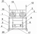
FIG. 4 is a schematic front view of the present invention;
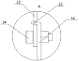
FIG. 5 is an enlarged view of the structure at A in FIG. 4;
FIG. 6 is a schematic view of a connection structure of a first connecting rod and a second connecting rod according to the present invention;
FIG. 7 is a schematic view of the retracted state of the auxiliary wheel according to the present invention;
FIG. 8 is a schematic view of the structure of the present invention cooperating with a guard rail of an expressway;
in the figure: 1. a support body; 2. a first storage rack; 3. a support bar; 4. a rubber wheel; 5. a first mounting block; 6. a fixing plate; 7. a second mounting block; 8. an auxiliary wheel; 9. a rail idler; 10. a rail wheel; 11. an anti-slip sleeve; 12. a push rod; 13. a first support frame; 14. an inclined bracket; 15. a flat support; 16. a base plate; 17. a second storage rack; 18. a first connecting rod; 19. an auxiliary wheel support; 20. reinforcing ribs; 21. a second support frame; 22. a rotation stopping block; 23. a second connecting rod; 24. a screw; 25. a collar; 26. mounting a third block; 27. a guardrail column; 28. a corrugated beam.
Detailed Description
The technical solutions in the embodiments of the present invention will be clearly and completely described below with reference to the drawings in the embodiments of the present invention, and it is obvious that the described embodiments are only a part of the embodiments of the present invention, and not all of the embodiments. All other embodiments, which can be derived by a person skilled in the art from the embodiments given herein without making any creative effort, shall fall within the protection scope of the present invention.
The invention provides the following technical scheme:
as shown in fig. 1-8, a high-speed rescue railcar comprises a supporting body 1, wherein four first mounting blocks 5 are fixed on the supporting body 1, and are uniformly and symmetrically distributed on two sides of the supporting body 1, a first storage rack 2 and a second storage rack 17 are respectively and movably connected to the first mounting blocks 5, the first storage rack 2 and the second storage rack 17 are arranged on the front side of the supporting body 1, and the first storage rack 2 and the second storage rack 17 are used for placing various rescue goods;
the bottom of the supporting main body 1 is connected with a rubber wheel 4, a reinforcing rib 20 is fixedly connected inside the supporting main body 1, the reinforcing rib 20 can stabilize and strengthen the integral structure of the invention, the bearing capacity of the invention is improved, a second supporting frame 21 is fixedly connected between the reinforcing rib 20 positioned above and the top of the supporting main body 1, one side of the second supporting frame 21 is fixedly connected with a flat bracket 15 which is arranged straightly, an inclined bracket 14 is fixedly connected with the top of the supporting main body 1, the inclined bracket 14 and one end of the flat bracket 15 far away from the supporting main body 1 are jointly and rotatably connected with a track wheel 10, the inclined bracket 14 and the flat bracket 15 are jointly connected with the track wheel 10, the inclined bracket 14, the flat bracket 15 and the supporting main body 1 form a triangular supporting structure which can stably support the track wheel 10, the track wheel 10 is obliquely arranged and arranged at the rear side of the supporting main body 1, and a plurality of mounting blocks II 7 are fixedly connected at the position of the supporting main body 1 close to the bottom, the second mounting block 7 is fixedly connected with a fixing plate 6, the fixing plates 6 are grouped in pairs, and a rail idler wheel 9 is movably connected between one group of fixing plates 6, the invention is used for expressway rescue and can move on an expressway guardrail, the expressway guardrail is divided into a guardrail upright post 27 and a wave-shaped beam 28 fixed on one side of the guardrail upright post 27, the rail wheel 10 in the invention can be placed at the top end of the wave-shaped beam 28, the rail idler wheel 9 can be attached to the wave crest position of the wave-shaped beam 28, the rail idler wheel 9 is arranged on the same side of the rail wheel 10, when an accident happens on an expressway and rescue goods and materials need to be conveyed urgently, and when the expressway is jammed, the rail wheel 10 is placed above the wave-shaped beam 28, and the rail idler wheel 9 is placed on the wave crest position of the wave-shaped beam 28, the invention can directly move on the expressway guardrail through the arrangement of the rail wheel 10, meanwhile, the volume of the invention on one side of the highway guardrail is smaller, so that when the highway and an emergency lane are blocked, the conveying process of the invention is not influenced, various rescue goods and materials can be quickly conveyed to an accident place, and the influence on the conveying of the rescue goods and materials caused by the lane blockage can be avoided by timely rescue;
the supporting main body 1 is further fixed with a third mounting block 26, the third mounting block 26 is movably connected with an auxiliary wheel support 19, one end of the auxiliary wheel support 19 is connected with an auxiliary wheel 8, and the auxiliary wheel support 19 is connected with the reinforcing rib 20 through an auxiliary wheel telescopic device.
Further scheme: the bottom of the support main body 1 is fixed with the bottom plate 16, the bottom plate 16 is arranged at the bottom of the second storage rack 17, two sides of the first storage rack 2 are connected with two sides of the support main body 1 through the support rods 3, and the support rods 3 are movably connected between the first storage rack 2 and the support main body 1 through the quick-release pins, in the invention, the second storage rack 17 can be supported due to the random folding and unfolding of the second storage rack 17, the rotating position of the second storage rack 17 can be limited, the first storage rack 2 can also rotate randomly, the rotating position of the first storage rack 2 can be limited through the support rods 3, meanwhile, the structure of the first storage rack 2 can also be supported, the support rods 3 are arranged through the quick-release pins, the support rods 3 can be fixed and detached more conveniently, and the first storage rack 2 can be folded and unfolded conveniently.
Further scheme: the second support frame 21 is of an H-shaped structure, the first support frame 13 is fixedly connected inside the flat support 15, the first support frame 13 is of a cross-shaped structure, and the stability of the rail wheel 10 is greatly enhanced by the second support frame 21 and the first support frame 13.
Further scheme: the first mounting block 5, the second mounting block 7, the third mounting block 26, the first storage rack 2, the second storage rack 17 and the support main body 1 are all made of aluminum alloy materials, and the aluminum alloy materials have the characteristics of light weight, low cost and high lightness, so that the connection structure between the rack and the support main body is firmer and more reliable, the overall weight of the rack is greatly reduced, the labor intensity of the rack during full load and no load is reduced, and the labor is saved during material conveying.
Further scheme: the first shelf 2 and the second shelf 17 are hollow frame structures, and are fixedly connected with a plurality of reinforcing rods, the first shelf 2 and the second shelf 17 are obliquely arranged on the support main body 1, and one side of the first shelf 2 and the second shelf 17 far away from the support main body 1 is higher than one side of the support main body 1, the first shelf 2 and the second shelf 17 with the hollow frame structures can reduce the weight of the first shelf 2 and the second shelf 17 and improve the bearing capacity of the first shelf 2 and the second shelf 17, and one side of the first shelf 2 and the second shelf 17 far away from the support main body 1 is higher than one side of the support main body 1, so that the first shelf 2 and the second shelf 17 are oblique towards one side of the support main body 1, when placing and conveying goods on the first shelf 2 and the second shelf 17, goods and materials on the first shelf 2 and the second shelf 17 are conveyed due to the first shelf 2, the second shelf 2, The inclination of the second storage rack 17 enables materials to be extruded and moved towards the direction of the supporting body 1 in the conveying process, and due to the blocking effect of the supporting body 1, the materials can be stopped on the first storage rack 2 and the second storage rack 17 well, the materials cannot move along the other side of the first storage rack 2 and the second storage rack 17, and the phenomenon that the materials fall off is avoided.
Further scheme: the top of the support main body 1 is fixedly connected with a push rod 12 which is arranged in a bending mode, the anti-skidding sleeve 11 is fixed at the tail end of the push rod 12, anti-skidding threads are arranged on the anti-skidding sleeve 11, the anti-skidding sleeve 11 is convenient to push the anti-skidding mechanism, and the anti-skidding sleeve 11 with the anti-skidding threads can prevent the anti-skidding mechanism from skidding when being pushed.
Further scheme: the auxiliary wheel telescopic device comprises a first connecting rod 18 and a second connecting rod 23, one end of the first connecting rod 18 is movably connected with one end of the second connecting rod 23 through a screw 24, lantern rings 25 are fixedly connected with one ends of the first connecting rod 18 and the second connecting rod 23 far away from the screw 24, one lantern ring 25 is sleeved on the auxiliary wheel support 19, the other lantern ring 25 is sleeved on the reinforcing rib 20, when the auxiliary wheel 8 is retracted, the whole auxiliary wheel support 19 is retracted to one side of the supporting main body 1, at the moment, because the first connecting rod 18 and the second connecting rod 23 are movably connected through the screw 24, the first connecting rod 18 and the second connecting rod 23 can rotate together along the position of the screw 24, meanwhile, the position of the screw 24 can extend upwards until the auxiliary wheel 8 is fully retracted to one side of the supporting main body 1, when the auxiliary wheel 8 is pulled open, the first connecting rod 18 and the second connecting rod 23 can rotate together under the driving of the auxiliary wheel support 19 until the first connecting, this allows the auxiliary wheel 8 to be pulled out more quickly.
Further scheme: the end, close to the screw 24, of the first connecting rod 18 is fixed with a rotation stopping block 22, a groove corresponding to the rotation stopping block 22 is formed in the second connecting rod 23, when the first connecting rod 18 and the second connecting rod 23 rotate to form a straight line, the rotation stopping block 22 can be clamped into the groove, when the auxiliary wheel support 19 is pulled continuously, the rotation stopping block 22 is matched with the groove, the movement of the first connecting rod 18 and the second connecting rod 23 can be further limited, when the auxiliary wheel 8 rolls and advances on the ground, the auxiliary wheel 8 can bear a force, the force can enable the auxiliary wheel 8 to be further opened outwards, and through the matching of the rotation stopping block 22 and the groove, the blocking initiative can be played, the auxiliary wheel 8 is prevented from causing the continuous movement of the auxiliary wheel support 19 due to rolling, and the normal use of the auxiliary wheel 8 is influenced.
Further scheme: the track depended wheel 9 is made for the nylon material, and rail wheel 10 is made for the aluminum alloy material, and all is equipped with the bearing in the middle of rail depended wheel 9 and rail wheel 10, and rail depended wheel 9 that the nylon material was made can avoid the rigid contact between rail depended wheel 9 and the wave form roof beam 28, and rail wheel 10 of aluminum alloy material has strengthened rail wheel 10's structure, has prolonged rail wheel 10's life, and the setting of bearing is convenient for rail wheel 10 and the rotation of rail depended wheel 9.
The working principle is as follows: firstly, various rescue goods and materials are placed on a first storage rack 2 and a second storage rack 17, when an accident happens on an expressway and the rescue goods and materials need to be transported emergently and the expressway is jammed, a rail wheel 10 is placed above a wave-shaped beam 28, a rail leaning wheel 9 is placed at the position of the wave crest of the wave-shaped beam 28 and an auxiliary wheel 8 is folded, then the rail can directly move on a guardrail of the expressway, meanwhile, the size of the rail on one side of the expressway is small, so that when the expressway and an emergency lane are jammed, the transportation process of the expressway emergency wheel device is not influenced, various rescue goods and materials can be rapidly transported to the place where the accident happens, the transportation of the rescue goods and materials is prevented from being influenced by the lane jam in time, when the expressway emergency wheel device advances on a straight road without any shelter, the auxiliary wheel 8 can be directly pulled open, and the auxiliary wheel 8 and the rubber wheel 4 are supported together, the invention can conveniently advance on a stable road surface, can bear heavy rescue goods and materials, facilitates the pushing process of the invention, and can quickly and stably convey the goods and materials to an accident place.
The preferred embodiments of the invention disclosed above are intended to be illustrative only. The preferred embodiments are not intended to be exhaustive or to limit the invention to the precise forms disclosed. Obviously, many modifications and variations are possible in light of the above teaching. The embodiments were chosen and described in order to best explain the principles of the invention and the practical application, to thereby enable others skilled in the art to best utilize the invention. The invention is limited only by the claims and their full scope and equivalents.
Claims (9)
1. The utility model provides a high-speed track car for rescue, includes supporting main part (1), its characterized in that: support be fixed with installation piece (5) on main part (1), installation piece (5) are equipped with four, and even symmetric distribution is in the both sides of supporting main part (1), there are supporter (2) and supporter two (17) respectively swing joint on installation piece (5), supporter (2) and supporter two (17) set up the front side at supporting main part (1), the bottom of supporting main part (1) is connected with rubber wheel (4), support main part (1) inside fixedly connected with strengthening rib (20), fixedly connected with support frame two (21) between strengthening rib (20) that are located the top and the top of supporting main part (1), flat support (15) that one side fixedly connected with of support frame two (21) set up, support main part (1) top fixedly connected with outrigger (14), outrigger (14) and flat support (15) keep away from the one end of supporting main part (1) and rotate jointly and are connected with the rail wheel (10) The track wheel (10) is obliquely arranged and arranged at the rear side of the supporting body (1), the supporting body (1) is close to a plurality of mounting blocks II (7) of the position of the bottom, the mounting blocks II (7) are fixedly connected with fixing plates (6), every two of the fixing plates (6) are in a group, a track idler wheel (9) is movably connected between a group of fixing plates (6), the track idler wheel (9) is arranged on the same side of the track wheel (10), a mounting block III (26) is further fixed on the supporting body (1), an auxiliary wheel support (19) is movably connected on the mounting block III (26), one end of the auxiliary wheel support (19) is connected with an auxiliary wheel (8), and the auxiliary wheel support (19) is connected with a reinforcing rib (20) through an auxiliary wheel telescopic device.
2. The high-speed rescue railcar according to claim 1, wherein: the bottom of supporting body (1) is fixed with bottom plate (16), bottom plate (16) set up the bottom at supporter two (17), supporter (2) both sides are passed through bracing piece (3) and are connected with the both sides of supporting body (1), just bracing piece (3) are through quick-release pin swing joint between supporter (2) and supporting body (1).
3. The high-speed rescue railcar according to claim 1, wherein: the second support frame (21) is of an H-shaped structure, a first support frame (13) is fixedly connected inside the flat support (15), and the first support frame (13) is of a # -shaped structure.
4. The high-speed rescue railcar according to claim 1, wherein: the mounting block I (5), the mounting block II (7), the mounting block III (26), the rack I (2), the rack II (17) and the support main body (1) are all made of aluminum alloy materials.
5. The high-speed rescue railcar according to claim 1, wherein: the rack is characterized in that the rack I (2) and the rack II (17) are hollow frame structures, and are fixedly connected with a plurality of reinforcing rods, the rack I (2) and the rack II (17) are obliquely arranged on the supporting body (1), and one side of the rack I (2) and the rack II (17) far away from the supporting body (1) is higher than one side of the rack I (1) close to the supporting body (1).
6. The high-speed rescue railcar according to claim 1, wherein: the support is characterized in that the top of the support main body (1) is fixedly connected with a push rod (12) which is arranged in a bending mode, the tail end of the push rod (12) is fixedly provided with an anti-skidding sleeve (11), and anti-skidding lines are arranged on the anti-skidding sleeve (11).
7. The high-speed rescue railcar according to claim 1, wherein: auxiliary wheel telescoping device includes connecting rod one (18) and connecting rod two (23), screw (24) swing joint is passed through with the one end of connecting rod two (23) in connecting rod one (18), the one end fixedly connected with lantern ring (25) of screw (24) is kept away from with connecting rod two (23) in connecting rod one (18), and one of them lantern ring (25) cover is established on auxiliary wheel support (19), and another lantern ring (25) cover is established on strengthening rib (20).
8. The high-speed rescue railcar according to claim 7, wherein: and one end of the first connecting rod (18) close to the screw (24) is fixedly provided with a rotation stopping block (22), and the second connecting rod (23) is provided with a groove corresponding to the rotation stopping block (22).
9. The high-speed rescue railcar according to claim 1, wherein: the track idler wheel (9) is made of nylon materials, the track wheel (10) is made of aluminum alloy materials, and bearings are arranged between the track idler wheel (9) and the track wheel (10).
Priority Applications (1)
| Application Number | Priority Date | Filing Date | Title |
|---|---|---|---|
| CN202110751176.0A CN113320342A (en) | 2021-07-02 | 2021-07-02 | Rail car for high-speed rescue |
Applications Claiming Priority (1)
| Application Number | Priority Date | Filing Date | Title |
|---|---|---|---|
| CN202110751176.0A CN113320342A (en) | 2021-07-02 | 2021-07-02 | Rail car for high-speed rescue |
Publications (1)
| Publication Number | Publication Date |
|---|---|
| CN113320342A true CN113320342A (en) | 2021-08-31 |
Family
ID=77425626
Family Applications (1)
| Application Number | Title | Priority Date | Filing Date |
|---|---|---|---|
| CN202110751176.0A Pending CN113320342A (en) | 2021-07-02 | 2021-07-02 | Rail car for high-speed rescue |
Country Status (1)
| Country | Link |
|---|---|
| CN (1) | CN113320342A (en) |
Cited By (1)
| Publication number | Priority date | Publication date | Assignee | Title |
|---|---|---|---|---|
| KR102537455B1 (en) * | 2022-10-21 | 2023-05-30 | (주)비전시그텍 | Hybrid tansport cart for maintenance of railway signal control equipment that can move by rail and road |
-
2021
- 2021-07-02 CN CN202110751176.0A patent/CN113320342A/en active Pending
Cited By (1)
| Publication number | Priority date | Publication date | Assignee | Title |
|---|---|---|---|---|
| KR102537455B1 (en) * | 2022-10-21 | 2023-05-30 | (주)비전시그텍 | Hybrid tansport cart for maintenance of railway signal control equipment that can move by rail and road |
Similar Documents
| Publication | Publication Date | Title |
|---|---|---|
| EP1686047B1 (en) | Folding Trailer | |
| CN204488859U (en) | A kind of indoor substation is logical barrier transport trolley fast | |
| CN113320342A (en) | Rail car for high-speed rescue | |
| DE102020002354B3 (en) | Foldable cargo bike | |
| CN215321835U (en) | Rail car for high-speed rescue | |
| CN211776431U (en) | Highway engineering construction safety device | |
| CN110761543A (en) | Urban vehicle movable type climbing operation platform suitable for urban vehicle maintenance | |
| CN105946938B (en) | A kind of multifunctional portable power assisting device for single express delivery | |
| CN210316436U (en) | Scaffold convenient to remove | |
| CN206598856U (en) | Small and labour-saving luggage truck is fluctuated when climbing building | |
| CN207860324U (en) | A kind of electric vehicle tilting prevention device of adjustable width | |
| CN206217928U (en) | A kind of folding dolly | |
| CN205292592U (en) | Worm wheel is from locking -type auxiliary trolley | |
| CN212507290U (en) | Frame ladder for building decoration | |
| CN206625470U (en) | A kind of ramp device for stair transformation adjustable inclination | |
| CN215154075U (en) | Tunnel type contact net operation car | |
| CN206327378U (en) | A kind of passenger train assembling and disassembling auxiliary device | |
| CN211622500U (en) | Urban vehicle movable type climbing operation platform suitable for urban vehicle maintenance | |
| CN213413997U (en) | Crawler-type stair climbing machine with foldable saddle | |
| CN109733916A (en) | Goods bridge | |
| CN220621277U (en) | Push-pull folding bicycle parking space | |
| CN215652090U (en) | Multi-purpose stretcher | |
| CN216617112U (en) | Reinforcing apparatus for building safety protection | |
| CN208515569U (en) | Collapsible carrying vehicle | |
| CN210433632U (en) | Quick current track rescue stretcher |
Legal Events
| Date | Code | Title | Description |
|---|---|---|---|
| PB01 | Publication | ||
| PB01 | Publication | ||
| SE01 | Entry into force of request for substantive examination | ||
| SE01 | Entry into force of request for substantive examination |