CN113315899B - Camera assembly, electronic equipment and control method thereof - Google Patents
Camera assembly, electronic equipment and control method thereof Download PDFInfo
- Publication number
- CN113315899B CN113315899B CN202110589965.9A CN202110589965A CN113315899B CN 113315899 B CN113315899 B CN 113315899B CN 202110589965 A CN202110589965 A CN 202110589965A CN 113315899 B CN113315899 B CN 113315899B
- Authority
- CN
- China
- Prior art keywords
- magnetic
- module
- camera
- dimmer
- lens
- Prior art date
- Legal status (The legal status is an assumption and is not a legal conclusion. Google has not performed a legal analysis and makes no representation as to the accuracy of the status listed.)
- Active
Links
Images


Classifications
-
- H—ELECTRICITY
- H04—ELECTRIC COMMUNICATION TECHNIQUE
- H04N—PICTORIAL COMMUNICATION, e.g. TELEVISION
- H04N23/00—Cameras or camera modules comprising electronic image sensors; Control thereof
- H04N23/57—Mechanical or electrical details of cameras or camera modules specially adapted for being embedded in other devices
-
- H—ELECTRICITY
- H04—ELECTRIC COMMUNICATION TECHNIQUE
- H04M—TELEPHONIC COMMUNICATION
- H04M1/00—Substation equipment, e.g. for use by subscribers
- H04M1/02—Constructional features of telephone sets
- H04M1/0202—Portable telephone sets, e.g. cordless phones, mobile phones or bar type handsets
- H04M1/026—Details of the structure or mounting of specific components
- H04M1/0264—Details of the structure or mounting of specific components for a camera module assembly
-
- H—ELECTRICITY
- H04—ELECTRIC COMMUNICATION TECHNIQUE
- H04N—PICTORIAL COMMUNICATION, e.g. TELEVISION
- H04N23/00—Cameras or camera modules comprising electronic image sensors; Control thereof
- H04N23/50—Constructional details
- H04N23/55—Optical parts specially adapted for electronic image sensors; Mounting thereof
-
- H—ELECTRICITY
- H04—ELECTRIC COMMUNICATION TECHNIQUE
- H04N—PICTORIAL COMMUNICATION, e.g. TELEVISION
- H04N23/00—Cameras or camera modules comprising electronic image sensors; Control thereof
- H04N23/60—Control of cameras or camera modules
-
- H—ELECTRICITY
- H04—ELECTRIC COMMUNICATION TECHNIQUE
- H04N—PICTORIAL COMMUNICATION, e.g. TELEVISION
- H04N23/00—Cameras or camera modules comprising electronic image sensors; Control thereof
- H04N23/70—Circuitry for compensating brightness variation in the scene
- H04N23/73—Circuitry for compensating brightness variation in the scene by influencing the exposure time
Abstract
The application provides a camera subassembly, electronic equipment and control method thereof, including at least one camera module, the camera module includes camera lens module, sensitization module, first actuating mechanism, at least one dimmer and second actuating mechanism. The lens module comprises at least two lenses; the photosensitive module is arranged opposite to the lens module; the first driving mechanism is connected with the lens module and is used for driving at least one lens in the lens module to move towards a direction away from the photosensitive module so as to form an accommodating space; the second driving mechanism is connected with the dimmer and is used for driving the dimmer to move into or out of the accommodating space. The application provides a camera assembly, electronic equipment and a control method thereof, wherein the camera assembly can simultaneously improve photographing effect and shooting effect.
Description
Technical Field
The application relates to the technical field of electronics, in particular to a camera assembly, electronic equipment and a control method thereof.
Background
At present, the development trend of camera components of electronic equipment such as mobile phones is to use a photosensitive module with larger size and to provide a lens module with larger aperture, so that a larger system light incoming amount and a smaller depth of field are obtained at the same time, and a user can obtain a picture with better quality. However, the mobile phone camera also needs to take account of the video recording function, when the light incoming amount of the camera system is large, the problem that the image is overexposed and the image capturing effect is poor may be caused in the process of capturing the video, so that the problem that the image capturing effect and the image capturing effect of the camera assembly in the electronic equipment are required to be solved is solved.
Disclosure of Invention
The application provides a camera assembly, electronic equipment and a control method thereof, wherein the camera assembly can simultaneously improve photographing effect and shooting effect.
In a first aspect, the present application provides a camera module, including at least one camera module, the camera module includes:
a lens module comprising at least two lenses;
the photosensitive module is arranged opposite to the lens module;
the first driving mechanism is connected with the lens module and is used for driving at least one lens in the lens module to move towards a direction away from the photosensitive module so as to form an accommodating space;
at least one dimmer;
the second driving mechanism is connected with the dimmer and used for driving the dimmer to move into or out of the accommodating space.
In a second aspect, the application provides an electronic device, electronic device include back lid, display screen and camera subassembly, back lid in the display screen and with the display screen surrounds and forms the accommodation space, the camera subassembly is located the accommodation space, back cover is last to be equipped with the intercommunication the through-hole in accommodation space, the camera subassembly warp the through-hole gathers light, first actuating mechanism is used for the drive the camera subassembly at least part of camera module is towards keeping away from the direction of display screen stretches out the through-hole or is retracted to the accommodation space.
In a third aspect, the present application provides a control method for an electronic device, where the electronic device includes a rear cover, a display screen, and a camera assembly, where the rear cover is covered on the display screen and surrounds the display screen to form a containing space, the camera assembly is disposed in the containing space, and the camera assembly includes a lens module, a photosensitive module, a first driving mechanism, at least one dimmer, a second driving mechanism, and a controller, the lens module includes at least two lenses, the photosensitive module is disposed opposite to the lens module, the first driving mechanism is connected to the lens module, and the second driving mechanism is connected to the dimmer; the method comprises the following steps:
the controller receives a shooting instruction and controls the first driving mechanism to drive at least one lens in the lens module to move towards a direction away from the photosensitive module according to the shooting instruction so as to form a containing space;
the controller receives an image pickup instruction and controls the second driving mechanism to drive the dimmer to move into the accommodating space according to the image pickup instruction;
the controller receives an image shooting end instruction and controls the second driving mechanism to drive the dimmer to move out of the accommodating space according to the image shooting end instruction;
The controller receives a shooting instruction and controls the first driving mechanism to drive at least one lens in the lens module to be close to the photosensitive module according to the shooting instruction.
According to the camera module, the electronic equipment and the control method thereof, when the camera module shoots, the first driving mechanism drives the inside of the lens module to form an accommodating space and/or forms a relatively larger distance between the driving lens module and the photosensitive module, so that the focal length of the camera module is increased, the shooting image quality is improved, and when shooting is finished, the inside of the driving lens module is retracted or the driving lens module and the photosensitive module are retracted, so that the thickness of the camera module in a storage state is small, and the camera module is conveniently formed in the light and thin electronic equipment; the relatively large space can form an accommodating space, the movable light reducer is arranged in the camera component, the light reducer is moved into the accommodating space through the second driving mechanism during shooting, the light reducer is not required to be additionally arranged, the light reducer can reduce overexposure during shooting video, the image quality of the video is improved, the original light path is basically unaffected, the light reducer is moved out of the accommodating space when shooting is finished, the light reducer does not occupy the thickness space of the camera component, the shooting effect and the shooting effect are improved at the same time, and the thickness stacking space of the camera component can be reduced.
Drawings
In order to more clearly illustrate the technical solutions of the embodiments of the present application, the drawings that are needed in the embodiments will be briefly described below, and it is obvious that the drawings in the following description are only some embodiments of the present application, and that other drawings can be obtained according to these drawings without inventive effort for a person skilled in the art.
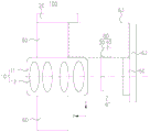
Fig. 1 is a schematic structural diagram of a camera assembly of an electronic device in a storage state according to an embodiment of the present application;
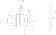
fig. 2 is an exploded view of an electronic device according to an embodiment of the present application;
fig. 3 is a schematic structural diagram of a camera assembly of an electronic device in an extended state according to an embodiment of the present application;
fig. 4 is a schematic structural diagram of a plurality of camera modules of an electronic device in an extended state according to an embodiment of the present application;
fig. 5 is a schematic structural diagram of a camera module in a storage state according to an embodiment of the present application;
FIG. 6 is a schematic view of a camera assembly of the type provided in FIG. 5 in an extended state;
fig. 7 is a schematic structural view of another camera module provided in an embodiment of the present application in a first extended state;
FIG. 8 is a schematic view of another camera head assembly provided in FIG. 7 in a second extended state;
fig. 9 is a schematic structural view of a dimmer according to an embodiment of the present application;
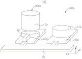
fig. 10 is a schematic structural view of a second driving mechanism driving a dimmer located in a storage space according to an embodiment of the present application;
fig. 11 is a schematic structural view of a second driving mechanism driving a dimmer located in an accommodating space according to an embodiment of the present disclosure;
fig. 12 is a schematic perspective view of a switching mechanism driving a dimming mechanism at a first storage position according to an embodiment of the present disclosure;
fig. 13 is a schematic structural view of a switching mechanism driving dimming mechanism at a first storage position according to an embodiment of the present disclosure;
fig. 14 is a schematic perspective view of a switching mechanism and a second driving mechanism for driving a dimmer to be located at a first working position according to an embodiment of the present application;
fig. 15 is a schematic diagram of a structure in which a switching mechanism provided in an embodiment of the present application drives a dimming mechanism to move from a first storage position toward a second storage position;
fig. 16 is a schematic diagram of a second structure in which the switching mechanism provided in the embodiment of the present application drives the dimming mechanism to move from the first storage position toward the second storage position;
fig. 17 is a schematic diagram III of a structure in which a switching mechanism provided in an embodiment of the present application drives a dimming mechanism to move from a first storage position toward a second storage position;
Fig. 18 is a schematic perspective view of a switching mechanism driving a dimming mechanism at a second storage position according to an embodiment of the present disclosure;
fig. 19 is a schematic perspective view of a switching mechanism and a second driving mechanism for driving a dimmer to be located at a second working position according to an embodiment of the present application;
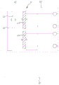
FIG. 20 is a block diagram of a control circuit for a camera assembly driving a lens module to eject and operate a dimming mechanism according to an embodiment of the present application;
FIG. 21 is a logic diagram of driving a lens module to eject and operate a dimming mechanism by a camera module according to an embodiment of the present disclosure;
FIG. 22 is a schematic diagram illustrating the operation of a dimming mechanism in another camera module according to the present disclosure;
fig. 23 is a second schematic structural diagram of the operation of the dimming mechanism in another camera module according to the embodiment of the present application;
fig. 24 is a schematic diagram III of the operation of a dimming mechanism in another camera module according to an embodiment of the present application;
FIG. 25 is a logic diagram of driving a lens module eject and dimming mechanism to operate using another camera assembly provided in an embodiment of the present application;
fig. 26 is a flowchart of a control method of an electronic device provided in an embodiment of the present application.
Reference numerals:
An electronic device 1000; a display screen 200; a housing 300; a middle frame 310; a frame 311; middle plate 312; a rear cover 320; the accommodating space 410; a through hole 420; a camera assembly 100; a camera module 500; a first camera module 500a; a second camera module 500b; a lens module 10; a lens barrel 11; a first sub-barrel 111; a second sub-barrel 112; a sub-barrel 110; a lens 12; a first lens group 121; a second lens group 122; a position sensor 130; a first drive mechanism 20; at least one dimmer 30; a light-reducing base material 31; a light reduction film 32; a buffer layer 33; a hardness layer 34; a second drive mechanism 40; a first magnetic track 41; a first magnetic slider 42; a first sub-magnetic member 411; a second sub-magnetic piece 412; a photosensitive module 50; a housing space 61; a storage space 63; an adjustment module 60; a substrate 62; a switching mechanism 70; a second magnetic slider 71; a first permanent magnet 711; a second permanent magnet 712; a second magnetic track 72; a third sub-magnetic element 721; a fourth sub-magnetic piece 722; a fifth sub magnetic member 723; a sixth sub-magnetic piece 724; a seventh sub-magnetic piece 725; an eighth child magnetic piece 726; a dimming mechanism 80; a flexible circuit board 90.
Detailed Description
The following description of the embodiments of the present application will be made clearly and fully with reference to the accompanying drawings, in which it is evident that the embodiments described are only some, but not all, of the embodiments of the present application. The embodiments listed in this application may be appropriately combined with each other.
Referring to fig. 1, an embodiment of the present application provides an electronic device 1000. The electronic device 1000 includes, but is not limited to, a cell phone, a telephone, a television, a tablet computer, a cell phone, a camera, a personal computer, a notebook computer, a vehicle mounted device, a wearable device, a personal digital assistant (Personal Digital Assistant, PDA), an electronic book reader, an MP3 (moving picture experts compression standard audio layer 3,Moving Picture Experts Group Audio Layer III) player, an MP4 (moving picture experts compression standard audio layer 4,Moving Picture Experts Group Audio Layer IV) player, a laptop portable computer, a desktop computer, a set top box, and the like. The wearable device is a portable electronic device 1000 that is worn directly with or integrated into a user's clothing or accessories, including but not limited to smart watches, rings, bracelets, necklaces, headphones, eyeglasses, hair bands, helmets, waist wears, wrist wears, arm wears, ankle wears, and the like. The embodiment of the application specifically describes taking the electronic device 1000 as a smart phone as an example.
Referring to fig. 1 and 2, an electronic device 1000 includes a display 200, a housing 300, and a camera assembly 100.
Taking the electronic device 1000 as an example of a mobile phone, the display 200 is generally rectangular. The display screen 200 is a module for the electronic device 1000 to display an image. The display 200 is disposed on the front surface of the electronic device 1000, and the front surface of the electronic device 1000 is also the surface that the user faces when using the electronic device 1000 normally. Display 200 includes, but is not limited to, a flexible display, a rigid display, a flexible display, a stretchable display, and the like. The types of display screen 200 include, but are not limited to, liquid crystal display (Liquid Crystal Display, LCD), light Emitting Diode (Light Emitting Diode, LED) display, organic Light-Emitting Diode (OLED) display, and the like. From the shape division of the display screen 200, the display screen 200 includes, but is not limited to, being flat plate-shaped or 2.5D curved or 3D curved, etc.
Referring to fig. 2, the housing 300 includes a middle frame 310 and a rear cover 320 according to a position division set in the electronic device 1000, wherein the middle frame 310 includes a frame 311 and a middle plate 312 set in the frame 311. The frame 311 is provided on the side of the electronic device 1000. The frame 311 is circumferentially connected to the display screen 200. When the electronic device 1000 is substantially rectangular, the frame 311 includes four sides to be disposed on four sides of the electronic device 1000 respectively. The middle plate 312 is disposed opposite to the display screen 200 in the thickness direction of the electronic device 1000. The middle plate 312 includes an aluminum alloy injection molded body, a plastic injection molded body, etc. disposed in the frame 311, and the middle plate 312 forms a main board, a battery, a housing cavity of various electronic devices, a mounting hole of a fixing member, etc., so that the main board, the battery, and the various electronic devices can be orderly and orderly mounted in the electronic device 1000. It will be appreciated that the screen of the display screen 200 in the present application may be relatively large, and the front projection of the display screen 200 in the thickness direction may completely cover the middle plate 312 or cover 80-100% of the middle plate 312. The area of the display screen 200 where the image is displayed accounts for 85-100% of the area of the entire front surface of the display screen 200.
Referring to fig. 1 and 2, the rear cover 320 is located on a side of the middle frame 310 facing away from the display screen 200. The rear cover 320 is covered on one side of the frame 311 away from the display screen 200. In this embodiment, the frame 311 and the rear cover 320 are two independent parts, and in other embodiments, the frame 311 and the rear cover 320 are integrally formed. The materials of the frame 311 and the back cover 320 are not specifically limited, and for example, the materials of the frame 311 and the back cover 320 include, but are not limited to, at least one of plastics, metals, ceramics, glass, and the like.
Referring to fig. 1 and 2, a housing 300 is enclosed on a peripheral side of a display screen 200, a rear cover 320 is covered on the display screen 200 and encloses a receiving space 410 with the display screen 200, and the camera assembly 100 is disposed in the receiving space 410. The rear cover 320 is provided with a through hole 420 communicating with the receiving space 410. The object side end of the camera assembly 100 is installed in the through hole 420, and light is collected through the through hole 420.
Referring to fig. 1 and 3, a camera assembly 100 in an electronic device 1000 provided in the present application is a pop-up camera. Fig. 1 and 3 are schematic structural diagrams of the camera module 100 in the electronic device 1000 in an ejected state and in a stored state, respectively.
Referring to fig. 4, the camera module 100 includes at least one camera module 500. In other words, the number of ejectable cameras (i.e., camera modules 500) in the electronic device 1000 provided herein is one or more. When the camera assembly 100 includes one camera module 500, the types of camera modules 500 include, but are not limited to, any of a master camera, a wide angle camera, a macro camera, a tele camera, and the like. The number of camera modules 500 in the electronic apparatus 1000 shown in fig. 4 is two, but is not limited to this number. When the camera assembly 100 includes a plurality of camera modules 500, the types of the camera modules 500 include, but are not limited to, a master camera, a wide-angle camera, a macro camera, a tele camera, and the like.
Referring to fig. 5, the camera module 100 at least includes a first driving mechanism 20, a lens module 10, a photosensitive module 50, and the like.
Referring to fig. 2 and fig. 5 together, the first driving mechanism 20 is configured to drive at least a portion (a part or all) of the lens module 10 of the camera assembly 100 to extend out of the through hole 420 or retract into the accommodating space 410 in a direction away from the display screen 200. In other words, the camera assembly 100 has an ejected state (see fig. 3) and a stored state (see fig. 1). Specifically, the length direction of the electronic device 1000 is the Y-axis direction, the width direction is the X-axis direction, and the thickness direction is the Z-axis direction. Wherein the optical axis direction of the camera assembly 100 is along the Z-axis direction. The camera assembly 100 is a camera that is retractable in the optical axis direction, or is referred to as a pop-up camera in the optical axis direction.
In the electronic device 1000 with a fixed camera, since the thickness of the module of the camera assembly 100 is limited due to the light and thin electronic device 1000, the area of the photosensitive module 50 (see fig. 5) is limited after the thickness of the module of the camera assembly 100 is limited, and thus, the photosensitive area of the camera assembly 100 is relatively small, so that the imaging definition, fidelity, etc. of the camera assembly 100 are affected to some extent. Moreover, the design of the existing camera assembly 100 is very sensitive to the height, and an excessively high module can cause the rear cover 320 of the electronic device 1000 to form an abrupt bulge, which affects the overall appearance of the electronic device 1000 such as a mobile phone.
According to the camera module 10, when the camera module 100 is in the pop-up state, the module thickness of the camera module 100 is not limited by the thickness of the electronic device 1000 any more, so that compatibility of relatively larger module thickness of the camera module 100 and relatively smaller thickness of the electronic device 1000 is realized. Because the camera module 100 has a relatively large thickness in the pop-up state, the size of the photosensitive module 50 of the camera module 100 can be relatively large (i.e., the outsole photosensitive module 50), so that the lighting area of the camera module 100 is relatively large, and an image with better quality can be obtained. In the present embodiment, the surface on which the photosensitive module 50 is located is substantially parallel to the X-Y surface, and since the electronic device 1000 itself has a large space on the X-Y surface, the electronic device 1000 also has a potential to house a large photosensitive module 50. When the camera module 100 is in the storage state, the lens module 10 is retracted to be stored in the storage space 410, and at this time, the camera module 100 will not form a convex protrusion on the rear cover 320, which is beneficial to the good appearance of the electronic device 1000 and the touch feeling of the user's hand touch.
When the camera module 100 of the electronic device 1000 uses the photosensitive module 50 with a larger size and is equipped with the lens module 10 with a larger aperture, a larger system light incoming amount and a smaller depth of field are obtained at the same time, so that a user can obtain a better quality picture, thereby obtaining a better dim light shooting effect. However, when the ambient brightness of the camera module 100 is high, the problem of overexposure may occur. The camera module 100 of the electronic device 1000 (e.g. mobile phone) needs to also have a video function, and when the light incoming amount of the system is large, the exposure time of a single frame needs to be reduced in order to avoid overexposure of a picture during video shooting. When shooting video, if the exposure time of a single frame picture is too short, the moving object in the picture lacks necessary fuzzy parts because the exposure time of each frame is too short, so that a viewer feels obvious fracture feeling when watching the picture, and the video picture is perceived as unsmooth.
The application provides a camera assembly 100 capable of effectively compatible shooting imaging effect and camera shooting effect without overexposure effect and electronic equipment 1000 with the camera assembly 100. The structure of the camera module 100 is described in detail below with reference to the accompanying drawings.
Referring to fig. 5, the camera module 500 includes a lens module 10, a photosensitive module 50, a first driving mechanism 20, at least one dimmer 30 and a second driving mechanism 40. The at least one dimmer 30 and the second driving mechanism 40 are also referred to as a dimming mechanism 80.
The lens module 10 includes a lens barrel 11 and at least two lenses 12 disposed in the lens barrel 11. Wherein the axial direction of the lens barrel 11 is along the Z-axis direction. The number, structure, and material of the lenses 12 are not particularly limited in this application. The optical axis direction of the lens module 10 is the Z-axis direction. At least two lenses 12 form a single group or multiple groups, not limited herein.
The photosensitive module 50 is disposed opposite to the lens module 10 in the optical axis direction. The photosensitive module 50 includes, but is not limited to, an image sensor or the like.
Referring to fig. 6, the first driving mechanism 20 is connected to the lens module 10. The first driving mechanism 20 is used for driving at least one lens 12 in the lens module 10 to move towards a direction away from the photosensitive module 50 so as to form a containing space 61.
Specifically, the first driving mechanism 20 is located on one side of the lens module 10 or disposed around the lens barrel 11. The first driving mechanism 20 is connected to the lens barrel 11. Alternatively, referring to fig. 6, the first driving mechanism 20 drives all the lens barrels 11 to move to drive the lens module 10 and the photosensitive module 50 to form a telescopic gap, so that the camera module 500 is in an extended state, the distance between the lens 12 and the photosensitive module 50 is within a distance range capable of forming a clear image, and the camera module 500 is in a working state. In this embodiment, the telescopic gap between the lens module 10 and the photosensitive module 50 can be determined as the accommodating space 61 for accommodating the dimmer 30. Referring to fig. 5, when the camera module 500 is in the storage state, the distance between the lens 12 and the photosensitive module 50 is smaller than the distance range for forming a clear image, and the camera module 500 is in the non-working state, at this time, the end face of the object side end of the camera module 500 is flush with the surface of the rear cover 320 or the end face of the object side end of the camera module 500 protrudes slightly from the surface of the rear cover 320. Optionally, the first driving mechanism 20 drives all the lens barrels 11 to move, so as to form a telescopic gap between the lens module 10 and the photosensitive module 50, and then drives a part of the lens barrels 11 to keep away from the photosensitive module 50, so that the telescopic gap generated between the lenses 12 and 12 forms a clear imaging light path, and the camera module 500 reaches a normal working state. In this embodiment, a telescopic gap generated between the lenses 12 and/or a telescopic gap formed between the head module and the photosensitive module 50 may be determined as the accommodation space 61 for accommodating the dimmer 30.
The dimmer 30 can reduce the light entering amount of the light path system in the high brightness environment, and ensure the long enough exposure time (such as 1/2 of the reciprocal of the frame rate, such as 1/60 second corresponding to 30 frames) and the continuity between video frames in the process of shooting video. The specific structure and number of the dimmer 30 are not particularly limited in this application. Alternatively, the dimmer 30 includes, but is not limited to, a dimmer having a uniform absorption effect for light of different wavelengths.
The second driving mechanism 40 is connected to the dimmer 30. The second driving mechanism 40 is used for driving the dimmer 30 to move into or out of the accommodating space 61. The dimmer 30 is located at one side of the lens module 10. When the accommodating space 61 appears, the second driving mechanism 40 drives the dimmer 30 to move into the accommodating space 61 under the shooting instruction, and the exposure of the light path is properly reduced under the condition of not changing the light path, so that the shooting effect is improved; after the image capturing is finished, the second driving mechanism 40 drives the dimmer 30 to move out of the accommodating space 61 under an image capturing finishing instruction, so as to facilitate the subsequent accommodating control of the lens module 10. In the above process, the dimmer 30 does not occupy the space of the accommodating state of the camera module 500; when the camera module 500 is in a working state, a telescopic gap is generated between the photosensitive module 50 and the lens module 10 due to the movement of the lens barrel 11, and the dimmer 30 can be moved into the telescopic gap, no additional position is required for the dimmer 30, and the dimmer 30 can reduce the light quantity of a part of the light without affecting the original light path basically.
According to the camera module 100 and the electronic device 1000 provided by the application, when the camera module 100 shoots, the first driving mechanism 20 drives the inside of the lens module 10 to form the accommodating space 61 and/or forms a relatively larger distance between the driving lens module 10 and the photosensitive module 50, so that the focal length of the camera module 100 is increased, the shooting image quality is improved, and when shooting is finished, the inside of the driving lens module 10 is retracted or the retraction of the driving lens module 10 and the photosensitive module 50 is performed, so that the thickness of the camera module 100 in a storage state is small, and the camera module 100 is conveniently formed in the light and thin electronic device 1000; the relatively large space can form the accommodating space 61, by arranging the movable dimmer 30 in the camera module 100, the dimmer 30 is moved into the accommodating space 61 through the second driving mechanism 40 during shooting, no additional position is required for the dimmer 30, the dimmer 30 can reduce overexposure during shooting video, the image quality of the video is improved, the original light path is basically not influenced, the dimmer 30 is moved out of the accommodating space 61 at the end of shooting, the dimmer 30 does not occupy the thickness space of the camera module 100, the shooting effect and the shooting effect are improved at the same time, and the thickness stacking space of the camera module 100 can be reduced.
Since the specifications of the camera module 500 of the current mobile phone make the relative light entering amount not reach the extent of affecting the video effect, the current mobile phone generally does not include the dimming mechanism 80. In the further development process of the electronic device 1000 such as a mobile phone, the skilled person in the application finds that too much light enters and affects the shooting effect in a specific scene (such as the outsole photosensitive module 50 and the large aperture). The skilled person proposes to provide a dimmer 30, such as a dimmer lens, in the camera module 500. Since the aperture structure changes the depth of field of the imaging system in addition to the amount of incoming light, an unexpected effect is generated on the picture effect. The use of the dimmer 30 can prevent the influence on the depth of field of the image while achieving uniform dimming, compared to the case where an aperture structure is provided for dimming. The technical staff reasonably utilizes the space originally formed by the camera module 500 in the working state to accommodate the dimmer 30, and proposes that the dimmer 30 is positioned outside the optical axis (outside the light path range) of the lens module 10 in the accommodating state of the camera module 500, so that the transverse space of the camera module 500 is fully utilized, and the increase of the height of the camera module 500 in the accommodating state is avoided.
In the present embodiment, the dimmer 30 is a dimmer mirror. Compared with the technical scheme that the dimming mirrors are fixedly arranged between the lenses 12 of the lens module 10, the lens module 10 is not required to be divided into a plurality of groups to provide the mounting space of the dimming mirrors, and the assembling difficulty of the front and rear lens groups is not increased because the structure and the mounting mode of the original lens module 10 are not required to be changed in the application; on the other hand, the dimming mirror installed in the lens module 10 cannot fully utilize the lateral space of the camera module 500, so that the axial length of the whole camera module 500 is increased, and the thickness of the whole camera module will be increased, which is contrary to the trend of pursuing the thinness of the electronic device 1000 at present; compared with the technical scheme that the dimming mirrors are fixedly arranged between the lenses 12 of the lens module 10, the transverse space of the camera module 500 is fully utilized, and the axial length of the whole camera module 500 is not increased, which is matched with the trend that the electronic device 1000 is pursued to be light and thin.
Compared with the technical scheme that the dimming mirror is fixedly arranged before the lens module 10 and the photosensitive module 50, the transverse space of the camera module 500 is fully utilized, and the axial length of the whole camera module 500 is not increased; because of the inclination existing in the assembly process of the two discrete components (the lens module 10 and the dimming mirror), the dimming mirror is directly arranged outside the lens module 10, so that extra aberration and parasitic light are easily introduced into the dimming mirror, in addition, the dimming mirror is directly arranged on the front side of the lens module 10 as a single component, the space inside the lens module 10 and the space between the lens module 10 and the photosensitive module 50 cannot be fully utilized, and the space inside the lens module 10 and the space between the lens module 10 and the photosensitive module 50 can be fully utilized, so that the space utilization rate inside the electronic device 1000 is improved.
Alternatively, referring to fig. 7 and 8, the accommodating space 61 is located between two adjacent lenses 12 in the lens module 10. Specifically, the lens barrel 11 may include a plurality of relatively movable sub-lens barrels 110. Each sub-lens barrel 110 is provided with a lens 12. The first driving mechanism 20 drives the lens barrel 11 to drive all the lenses 12 to be far away from the photosensitive module 50 under the first extending instruction, so that a part of the lens barrel 11 extends out of the surface of the rear cover 320, and is in a first extending state of the camera module 500 at this time; after the lens module 10 is far away from the photosensitive module 50, the distance between the lens module 10 and the photosensitive module 50 (i.e. back focus) is increased, so as to meet the back focus distance requirement of being able to collect clear images; the first driving mechanism 20 drives a part of the sub-lens barrels 110 to be further away from the photosensitive module 50 under the second extending instruction, so that a telescopic gap is generated between the lenses 12 and the lenses 12, that is, a telescopic gap is formed between adjacent sub-lens barrels 110, so as to increase the path of the light path, and at the moment, the camera module 500 can form a clear imaging light path, and at the moment, the second extending state of the camera module 500 is achieved; when the camera module 500 performs image capturing, the second driving mechanism 40 drives the dimmer 30 under the image capturing command to enter the telescopic gap between the lenses 12 through the telescopic gap between the sub-lens barrels 110, that is, the telescopic gap between two adjacent lenses 12 in the lens module 10 due to extension is used as the accommodating space 61, so that the telescopic gap between two adjacent lenses 12 in the lens module 10 due to extension is effectively utilized, and the utilization rate of the internal space of the camera module 500 is improved while the reduction of the exposure for image capturing of the camera module 500 is realized to improve the video effect.
Alternatively, referring to fig. 5 and 6, the accommodating space 61 is located between the lens module 10 and the photosensitive module 50. Specifically, whether the first driving mechanism 20 drives all the lens barrels 11 to extend in a single stage or drives all the lens barrels 11 to extend first and then drives part of the lens barrels 11 to extend further, the position of the light reducer 30 is designed to correspond to the position of a telescopic gap formed between the lens module 10 and the photosensitive module 50, so that the light reducer 30 can move into the telescopic gap formed between the lens module 10 and the photosensitive module 50.
When the position where the dimmer 30 is located is the back focal space of the lens module 10, the influence on the imaging quality due to the spatial interference between the lens module 10 and the dimmer 30 can be avoided.
Of course, in other embodiments, the number of the light reducers 30 is plural, and the plurality of light reducers 30 may be disposed in the same expansion gap. When the telescopic gaps are formed between the lens module 10 and the photosensitive module 50 and inside the lens module 10, a portion of the plurality of light absorbers 30 may be disposed in one of the telescopic gaps, and another portion of the plurality of light absorbers 30 may be disposed in the other telescopic gap. The material of the light-reducing substrate comprises resin or glass. The material of the light-reducing film comprises at least one of silicon dioxide, chromium and nickel.
Alternatively, referring to fig. 9, the dimmer 30 is a dimmer. The dimmer 30 includes a dimming substrate 31 and a dimming film 32 provided on at least one side of the dimming substrate 31. The light-reducing film 32 is used for transmitting light of a predetermined wavelength band and absorbing or reflecting light outside the predetermined wavelength band. Specifically, the typical structure of the light-reducing mirror is a light-reducing substrate 31 with multiple layers of different material film systems coated on both sides of the substrate. The material of the light-reducing substrate 31 includes, but is not limited to, a resin such as polyethylene terephthalate (PET) or a glass base. The material of the film system includes, but is not limited to, dielectric such as silicon dioxide or metal alloy such as chromium and nickel. Specifically, the type of film system. The light-reducing lens may have a reflective light-reducing lens and an absorptive light-reducing lens. The light rays of the reflective type light reducing lens except the light rays entering the photosensitive module 50 through the light reducing lens are reflected and enter the lens module 10 again, which may cause flare light spots on the image. And the light rays except the transmitted light rays in the absorption type light reducing lens are absorbed by the film layer. Alternatively, an absorption-type light-reducing mirror is used in this embodiment.
Referring to fig. 9, the light reducer 30 further includes a buffer layer 33 disposed between the light reducing substrate 31 and the light reducing film 32, so as to reduce stress generated by deposition, thereby reducing deformation of the light reducing mirror caused by the stress, and avoiding degradation of imaging quality of the lens module 10 caused by the deformed light reducing mirror; and/or, the dimmer 30 further comprises a hardness layer 34 arranged on the outer surface, wherein the hardness layer 34 is a film layer with higher hardness, so that abrasion possibly occurring in the movement process is avoided; and/or, the light reducer 30 further comprises an anti-reflection film (not shown) disposed between the light reducing substrate 31 and the light reducing film 32 or disposed on a side of the light reducing film 32 away from the light reducing substrate 31, so as to further reduce the possibility of multiple reflections of the reflected light in the system, and avoid the occurrence of parasitic light.
Optionally, referring to fig. 5 and 6, the camera module 100 further includes an adjusting module 60. The adjusting module 60 is circumferentially connected to the lens module 10. The adjustment module 60 includes at least one of a focus adjustment module (e.g., an autofocus module), an optical anti-shake module. The dimmer 30 is at least partially opposed to the adjustment module 60 when removed from the receiving space 61. Alternatively, the focusing module and the optical anti-shake module may be integrated into a single adjustment module 60. The adjusting module 60 is retracted together with the lens module 10 driven by the first driving mechanism 20, so as to act on the lens module 10 when the lens module 10 is in the extended state, so as to realize the functions of automatic focusing and optical anti-shake of the camera module 500.
Further, referring to fig. 5 and 6, the camera module 100 further includes a substrate 62. The substrate 62 is disposed opposite to and spaced apart from the adjustment module 60 and the lens module 10. The photosensitive module 50 is disposed on a side of the substrate 62 facing the lens module 10. The substrate 62 includes, but is not limited to, a rigid circuit board, a flexible circuit board with steel supplements, a rigid-flex board, and the like.
Referring to fig. 5 and 6, since the adjusting module 60 is circumferentially connected to the lens module 10 and stretches and contracts with the lens module 10, the adjusting module 60 increases the lateral dimension (X-Y plane) of the camera module 500. The space between the base plate 62 and the adjustment module 60 forms a receiving space 63. At least part of the dimmer 30 and the second driving mechanism 40 are positioned in the accommodating space 63 when the camera module 100 is in an un-imaged state, so that the space originally formed in the camera module 500 is fully utilized, the space utilization is improved, the increase of the size of the camera module 500 is reduced, and the miniaturization of the camera module 500 is promoted; meanwhile, the dimmer 30 is located in the accommodating space 63 and is relatively close to the lens module 10 and the photosensitive module 50, so that the dimmer can quickly enter the telescopic gap when the telescopic gap is formed between the lens module 10 and the photosensitive module 50, and the response speed of video shooting is improved.
For the technical solution that the accommodating space 61 is formed inside the lens module 10, at least part of the dimmer 30 and the second driving mechanism 40 may be disposed in a space formed between a side of the adjusting module 60 facing away from the substrate 62 and the rear cover 320.
The camera assembly 100 also includes a controller (not shown). The controller is electrically connected to the first driving mechanism 20 and the second driving mechanism 40. The first driving mechanism 20 includes, but is not limited to, a motor, a screw, and the like. The second drive mechanism 40 will be described in detail later. When the camera module 500 enters the shooting state, the controller controls the first driving mechanism 20 to drive at least part of the lens module 10 (or drive the lens module 10 and the adjusting module 60) to move from the initial position away from the photosensitive module 50 to the imaging position and form the accommodating space 61, thereby realizing an imaging light path and obtaining an image with high definition. When the camera module 500 enters the image capturing state, the controller controls the second driving mechanism 40 to drive the dimmer 30 (which can be along the plane perpendicular to the optical axis) to move into the accommodating space 61 and enter the imaging optical path of the system, so that the aperture increase or the video exposure effect brought by the large-bottom image sensor is reduced, and the video imaging quality is improved. After the camera assembly 100 finishes shooting, the controller controls the second driving mechanism 40 to drive the dimmer 30 to move out of the accommodating space 61. After the camera module 500 finishes shooting, the controller controls the first driving mechanism 20 to drive at least part of the lens module 10 (or drive the lens module 10 and the adjusting module 60) to approach the photosensitive module 50 until at least part of the lens module 10 is restored to the initial position.
The second driving mechanism 40 provided in the present application is specifically illustrated below with reference to the accompanying drawings, and of course, the second driving mechanism 40 includes, but is not limited to, the following embodiments.
Referring to fig. 10, the second driving mechanism 40 includes a first magnetic track 41 and a first magnetic slider 42. The first magnetic rail 41 is located outside the accommodation space 61 and intersects the optical axis direction of the lens module 10. The first magnetic track 41 is located in the X-Y plane and extends in the Y-axis direction or the X-axis direction. Optionally, the first magnetic track 41 extends in the X-axis direction. The first magnetic slider 42 is fixed to the dimmer 30. Specifically, the first magnetic slider 42 is fixed to an end of the dimmer 30 away from the accommodating space 61. The first magnetic slider 42 is disposed opposite to and spaced apart from the first magnetic track 41. The controller is electrically connected to the first magnetic track 41 and/or the first magnetic slider 42, and the controller is used for controlling the magnetic field intensity and direction of the first magnetic slider 42 and/or the first magnetic track 41, so that the first magnetic slider 42 drives the dimmer 30 to move into or out of the accommodating space 61 under the magnetic force of the first magnetic track 41. Optionally, the first magnetic slider 42 is a permanent magnet, and the first magnetic track 41 includes a plurality of electromagnets; alternatively, the first magnetic slider 42 is an electromagnet, and the first magnetic track 41 includes a plurality of electromagnets; alternatively, the first magnetic slider 42 is an electromagnet and the first magnetic track 41 includes a plurality of permanent magnets. The controller controls the magnetic field strength and direction of the electromagnet by controlling the magnitude and direction of the current flowing through the electromagnet.
Further, the first magnetic rail 41 is provided with a first slide (not shown) extending in the first direction (X-axis direction). The first slide and the first magnetic track 41 are stacked in the Z-axis direction and arranged in parallel in the X-axis direction. The first magnetic slider 42 is disposed on the first slideway and slides along the first slideway under the magnetic force of the first magnetic track 41. Further, the first magnetic slider 42 and the first slide rail are engaged with each other in the Z-axis direction, so that the first slide rail can restrict the movement of the first magnetic slider 42 in the Z-axis direction. The first slide may be engaged with the bottom, waist or top of the first magnetic slider 42, which is not limited herein. Optionally, the first slideway is of a hollow structure, so that no magnetic interference exists between the first magnetic slider 42 and the first magnetic track 41, a better magnetic field is formed, and magnetic force transmission with higher efficiency is performed.
Alternatively, referring to fig. 10 and 11, the first magnetic track 41 includes a plurality of first magnetic members arranged along a first direction (X-axis direction). The first direction is the X-axis direction. The first magnetic member is an electromagnet and the first magnetic slider 42 is a permanent magnet. The position of the dimmer 30 in the housing space 63 is defined as a housing position, and the position of the dimmer 30 in the housing space 61 is defined as an operating position. In the present embodiment, the number of the first magnetic elements is 2, wherein the first magnetic element relatively close to the accommodating space 61 is the first sub-magnetic element 411, and the first magnetic element relatively far from the accommodating space 61 is the second sub-magnetic element 412. The first sub-magnetic element 411 and the second sub-magnetic element 412 are both electromagnets and have opposite polarities.
When the dimmer 30 is located at the storage position, the first magnetic slider 42 is opposite to the second magnetic sub-piece 412 and is disposed at an interval, at this time, the controller controls the second magnetic sub-piece 412 to magnetically attract the first magnetic slider 42, the first magnetic slider 42 is kept fixed under the magnetic attraction of the second magnetic sub-piece 412, and the dimmer 30 is located at one side of the first magnetic slider 42 away from the second magnetic sub-piece 412.
In the process that the dimmer 30 moves into the accommodating space 61 from the accommodating position, the controller controls the first magnetic part (i.e., the first sub-magnetic part 411) relatively close to the accommodating space 61 to generate magnetic attraction force on the first magnetic sliding block 42, and controls the first magnetic part (i.e., the second sub-magnetic part 412) relatively far away from the accommodating space 61 to generate magnetic repulsive force on the first magnetic sliding block 42, and the first magnetic sliding block 42 moves towards the accommodating space 61 along the first slideway under the magnetic pulling force of the first sub-magnetic part 411 and the magnetic pushing force of the second magnetic part until the first magnetic sliding block 42 is opposite to the first sub-magnetic part 411, and at this time, the dimmer 30 is located at the working position. Since the first sub-magnetic member 411 generates magnetic attraction to the first magnetic slider 42, the first magnetic slider 42 is kept fixed to fix the dimmer 30 in the operating position. Optionally, a first limiting member (not shown) is disposed at an end of the first slide close to the accommodating space 61, where the first limiting member is used to limit the first magnetic slider 42 to drive the dimmer 30 to move to the working position, so that the dimmer 30 can move to the same position in each working, and uniformity of dimming effect of each time is maintained.
In the process of moving the dimming mirror out of the accommodating space 61 from the working position, the controller controls the first magnetic piece (i.e. the first sub-magnetic piece 411) relatively close to the accommodating space 61 to generate magnetic repulsive force on the first magnetic slide 42 by changing the current flow direction of the first sub-magnetic piece 411 and the current flow direction of the second sub-magnetic piece 412, and controls the first magnetic piece (i.e. the second sub-magnetic piece 412) relatively far from the accommodating space 61 to generate magnetic attractive force on the first magnetic slide 42, wherein the first magnetic slide 42 moves towards the accommodating space 63 along the first slide way under the magnetic push force of the first sub-magnetic piece 411 and the magnetic pull force of the second magnetic piece until the first magnetic slide 42 is opposite to the second sub-magnetic piece 412, and the dimming mirror 30 is located at the accommodating position. Since the second sub-magnetic member 412 generates magnetic attraction to the first magnetic slider 42, the first magnetic slider 42 is kept fixed to fix the dimmer 30 in the stowed position. Optionally, a second limiting member (not shown) is disposed at an end of the first slide away from the accommodating space 61, where the second limiting member is used to limit the first magnetic slider 42 to drive the dimmer 30 to move to the accommodating position, so that the dimmer 30 can move to the same position when being accommodated each time, and system stability of the camera module 100 is improved.
Fig. 10 and 11 are schematic views of the structure of the second driving mechanism 40 driving the dimmer 30 to be located in the accommodating space 61. In the present embodiment, the dimmer 30 is a dimmer mirror. In order to stabilize the motion of the light-reducing lens driven by the second driving mechanism 40, a magnet (i.e. the first magnetic slider 42) needs to be fixed on the substrate of the light-reducing lens, and the material of the magnet may be neodymium-iron-boron magnet or the like. In order to ensure that the light reducing lens does not deform in the working process, the light reducing lens can be fixed on a structural member made of resin or plastic, so that the reliability of the light reducing lens is improved.
The principle of the second driving mechanism 40 is electromagnetic driving, a permanent magnet (i.e. the first magnetic sliding block 42) is fixed on the light reducing lens, the permanent magnet is used for driving the light reducing lens to move towards a specific direction, the fixed portion of the second driving mechanism 40 is bonded with the base plate 62 of the camera assembly 100 through glue, the second driving mechanism 40 and other components of the camera assembly 100 are not moved relatively in the working process, two coils (the two coils respectively form the first sub magnetic piece 411 and the second sub magnetic piece 412) are arranged on the fixed portion, the number of turns of the two coils is equal, but the polarities of the external electrodes are opposite, and therefore the two coils generate opposite magnetic field distribution in the electrified state.
When the dimming mirror is in the storage state, the magnetic field generated by the second sub-magnetic part 412 is opposite to the permanent magnet (i.e. the first magnetic slider 42) on the dimming mirror, and the magnetic field generated by the first sub-magnetic part 411 is opposite to the first magnetic slider 42, so that the dimming mirror is fixed at the storage position without collision with other components of the module due to the movement of the whole electronic device 1000, and abrasion is caused. When the dimming mirror is in the working state, the input currents of the two coils are reversed, so that opposite magnetic fields are generated, the same poles of the second sub-magnetic piece 412 and the first magnetic sliding block 42 repel each other to push the dimming mirror away from the storage position, the first sub-magnetic piece 411 and the first magnetic sliding block 42 attract each other to fix the dimming mirror at the working position, and if the dimming mirror is out of the working mode, the polarities of the two coils are reversed again, so that the dimming mirror is sent to the storage position.
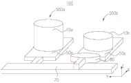
The above is an embodiment of the camera module 500, and of course, the camera module 100 provided in the present application includes at least one camera module 500. Referring to fig. 12, at least one camera module 500 includes a first camera module 500a and a second camera module 500b disposed side by side along a second direction. In this embodiment, the second direction is the Y-axis direction. At least one of the first camera module 500a and the second camera module 500b is a retractable camera module. In this embodiment, the first camera module 500a and the second camera module 500b are telescopic camera modules, and can achieve the dimming function. The dimming mechanism 80 of the first camera module 500a and the dimming mechanism 80 of the second camera module 500b may be independent from each other. In this embodiment, the first camera module 500a and the second camera module 500b share a set of light-reducing mechanism 80, and the light-reducing mechanism 80 includes at least one light-reducing device 30 and the second driving mechanism 40.
Further, referring to fig. 12, the camera module 100 further includes a switching mechanism 70 extending along the second direction. The switching mechanism 70 is used for driving the dimmer 30 and the second driving mechanism 40 to switch between the first camera module 500a and the second camera module 500 b. When the first camera module 500a needs to perform dimming, the switching mechanism 70 moves the dimmer 30 and the second driving mechanism 40 to the first camera module 500a; when the second camera module 500b needs to dim light, the switching mechanism 70 moves the dimmer 30 and the second driving mechanism 40 to the second camera module 500b, so that the dimming effect of the first camera module 500a and the second camera module 500b can be satisfied, but excessive parts are not added, so that the overall structure of the camera assembly 100 is relatively simple.
Specifically, referring to fig. 12 and 13 together, the switching mechanism 70 further includes a second magnetic slider 71 and a second magnetic track 72. The second magnetic track 72 is located at one side of the first camera module 500a and the second camera module 500 b. The second magnetic track 72 is located in the X-Y plane and extends in a second direction (Y-axis). The second magnetic slider 71 is disposed opposite to and spaced apart from the second magnetic track 72. The second magnetic slider 71 is fixed to the second driving mechanism 40 and the dimmer 30. Specifically, the second magnetic slider 71 is fixed at an end of the second driving mechanism 40 away from the first camera module 500a or the second camera module 500 b. The second drive mechanism 40 is located on the side of the second magnetic slider 71 facing away from the second magnetic track 72. The dimmer 30 is fixed to a side of the second driving mechanism 40 facing away from the second magnetic slider 71.
The controller is electrically connected to the second magnetic slider 71 and/or the second magnetic track 72. The controller is configured to control the magnetic field strength and direction of the second magnetic slider 71 and/or the second magnetic track 72, so that the second magnetic slider 71 drives the second driving mechanism 40 and the dimmer 30 to switch between the accommodating space 63 of the first camera module 500a and the accommodating space 63 of the second camera module 500b along the second direction (Y-axis direction) under the magnetic force of the second magnetic track 72.
Optionally, the second magnetic slider 71 comprises a permanent magnet and the second magnetic track 72 comprises a plurality of electromagnets; alternatively, the second magnetic slider 71 includes an electromagnet, and the second magnetic track 72 includes a plurality of electromagnets; alternatively, the second magnetic slider 71 comprises an electromagnet and the second magnetic track 72 comprises a plurality of permanent magnets. The controller controls the magnetic field strength and direction of the electromagnet by controlling the magnitude and direction of the current flowing through the electromagnet.
Further, a second slideway (not shown) extending in the second direction (Y-axis direction) is provided on the second magnetic track 72. The second slide and the second magnetic track 72 are stacked in the Z-axis direction and arranged in parallel in the Y-axis direction. The second magnetic slider 71 is disposed on the second slideway and slides along the second slideway under the magnetic force of the second magnetic track 72. Further, the second magnetic slider 71 and the second slide rail are engaged with each other in the Z-axis direction, so that the second slide rail constrains the movement of the second magnetic slider 71 in the Z-axis direction. The second slide may be engaged with the bottom, waist or top of the second magnetic slider 71, which is not limited herein. Optionally, the second slide way is of a hollow structure, so that no magnetic interference exists between the second magnetic slider 71 and the second magnetic track 72, a better magnetic field is formed, and magnetic force transmission with higher efficiency is performed.
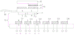
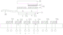
Optionally, referring to fig. 13, the second magnetic track 72 includes a plurality of second magnetic members arranged in a second direction (Y-axis direction). The second magnetic member is an electromagnet and the second magnetic slider 71 is a permanent magnet. The position of the dimmer 30 and the second driving mechanism 40 in the accommodation space 63 in the first camera module 500a is defined as a first accommodation position, the position of the dimmer 30 in the accommodation space 61 in the first camera module 500a is defined as a first operation position, the position of the dimmer 30 and the second driving mechanism 40 in the accommodation space 63 in the second camera module 500b is defined as a second accommodation position, and the position of the dimmer 30 in the accommodation space 61 in the second camera module 500b is defined as a second operation position. In the present embodiment, the number of the second magnetic members is 6, but the number is not limited to this. The 6 second magnetic elements are a third sub-magnetic element 721, a fourth sub-magnetic element 722, a fifth sub-magnetic element 723, a sixth sub-magnetic element 724, a seventh sub-magnetic element 725 and an eighth sub-magnetic element 726 in the direction from the first camera module 500a to the second camera module 500 b. Optionally, the second magnetic track 72 further includes a flexible circuit board 90, and the plurality of second magnetic elements are electrically connected to the flexible circuit board 90.
Referring to fig. 13, the second magnetic slider 71 includes two (but not limited to) permanent magnets with opposite poles, which are arranged along the Y-axis direction, and are defined as a first permanent magnet 711 and a second permanent magnet 712, respectively. The second magnetic slider 71 can improve the movement stability of the second magnetic slider 71 on the second magnetic track 72 by providing two or more permanent magnets.
Referring to fig. 12 and 13, when the second driving mechanism 40 is located at the first storage position, the first permanent magnet 711 and the second permanent magnet 712 are respectively opposite to the third sub-magnetic element 721 and the fourth sub-magnetic element 722 and are spaced apart, wherein the second permanent magnet 712 is close to the second camera module 500b relative to the first permanent magnet 711. At this time, the controller controls the third sub-magnetic part 721 to magnetically attract the first permanent magnet 711, and controls the fourth sub-magnetic part 722 to magnetically attract the second permanent magnet 712. Since the polarities of the first permanent magnet 711 and the second permanent magnet 712 are opposite, the third sub-magnetic member 721 and the fourth sub-magnetic member 722 are opposite in magnetism. The second magnetic slider 71 is held fixed by the magnetic attraction of the second sub-magnetic member 412, so that the second driving mechanism 40 is fixed at the first storage position.
Referring to fig. 12 and 14, when the second driving mechanism 40 is located at the first storage position, the second driving mechanism 40 can drive the dimmer 30 to move between the first storage position and the first working position, so as to dim the second camera module 500b, and the detailed process can refer to the embodiment of the second driving mechanism 40 driving the dimmer 30 to move between the working position and the storage position, which is not described herein. At this time, the fifth through eighth sub-magnetic members 723 through 726 may be de-energized to avoid generating a force on the second magnetic slider 71, thereby improving the stability of the second magnetic slider 71 in the first storage position.
Referring to fig. 15 to 17, during the process of moving the second magnetic slider 71 from the first camera module 500a to the second camera module 500b, the controller controls the second magnetic member relatively close to the second camera module 500b to generate magnetic attraction force on the second magnetic slider 71, and controls the second magnetic member relatively close to the first camera module 500a to generate magnetic repulsion force on the second magnetic slider 71.
Specifically, referring to fig. 15, when the controller receives a command to move the dimming mechanism 80 (including the dimming device 30 and the second driving mechanism 40) from the first camera module 500a to the second camera module 500b, the controller controls the fifth sub-magnetic member 723 to generate magnetic attraction to the second permanent magnet 712, and at this time, the magnetic pole of the fifth sub-magnetic member 723 is the same as the magnetic pole of the fourth sub-magnetic member 722, and the magnetic pole of the fifth sub-magnetic member 723 is opposite to the magnetic pole of the third sub-magnetic member 721, so that the dimming mechanism 80 moves along the second slideway toward the second camera module 500 b. Subsequently, referring to fig. 16, the controller controls the fourth sub-magnetic member 722 to generate magnetic attraction to the first permanent magnet 711, controls the fourth sub-magnetic member 722 to generate magnetic repulsion to the second permanent magnet 712 until the fourth sub-magnetic member 722 is opposite to and attracted to the first permanent magnet 711, and the fifth sub-magnetic member 723 is opposite to and attracted to the second permanent magnet 712, at this time, the third sub-magnetic member 721 may be de-energized. Further, referring to fig. 17, the sixth sub-magnetic member 724 is controlled to attract the second permanent magnet 712, so that the second magnetic slider 71 continues to move towards the direction in which the second camera module 500b is located, then the fifth sub-magnetic member 723 is controlled to attract the first permanent magnet 711, the fourth sub-magnetic member 722 is not energized, so that the fifth sub-magnetic member 723 is opposite to and attracts the first permanent magnet 711, the sixth sub-magnetic member 724 is opposite to and attracts the second permanent magnet 712, and so on until the seventh sub-magnetic member 725 is opposite to and attracts the first permanent magnet 711, and the eighth sub-magnetic member 726 is opposite to and attracts the second permanent magnet 712, so that the dimmer 30 and the second driving mechanism 40 are fixed at the second storage position.
Referring to fig. 18 and 19, when the second driving mechanism 40 is fixed at the second storage position, the second driving mechanism 40 can drive the dimmer 30 to move to the second working position along the X-axis direction to dim the second camera module 500b, and the specific process can refer to the embodiment in which the second driving mechanism 40 drives the dimmer 30 to move between the working position and the storage position.
It will be appreciated that the opposite ends of the second slide are provided with respective stop members to define the first and second storage positions of the second magnetic slider 71.
Fig. 12, 14, 18 and 19 are schematic views of the light reduction mechanism 80 moving between the plurality of pop-up camera modules 500. The present application proposes that the light reduction mechanism 80 is applied to the plurality of camera modules 500 and is provided with a switching mechanism 70, and the implementation manner of the switching mechanism 70 may adopt a driving manner similar to that of the second driving mechanism 40, and the movement direction of the switching mechanism 70 driving the second driving mechanism 40 is parallel to the arrangement direction of the plurality of camera modules 500.
The lens module 10 defining the first camera module 500a is a first lens module 10a, the light sensing module 50 defining the first camera module 500a is a first light sensing module 50a, the lens module 10 defining the second camera module 500b is a second lens module 10b, and the light sensing module 50 defining the second camera module 500b is a second light sensing module 50b.
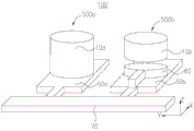
Referring to fig. 14, when the first camera module 500a is in operation, the first lens module 10a is driven by the first driving mechanism 20 connected thereto to move to a first extended position (an imaging position of the first camera module 500 a) along the positive Z-axis direction, and a first accommodating space 61 is formed between the first lens module 10a and the first photosensitive module 50 a. Then, the light reducing lens enters the imaging light path (i.e. enters the first working position of the first accommodating space 61) along the positive direction of the X-axis under the driving of the second driving mechanism 40, so as to perform the light reducing effect on the first camera module 500 a. Referring to fig. 12, when the second camera module 500b is switched to operate, the light-reducing lens first exits the light path (moves to the first storage position) along the opposite direction of the X-axis under the driving of the second driving mechanism 40. Referring to fig. 18, the light reducing mirror and the second driving mechanism 40 are then moved to the second camera module 500b (second storage position) by the switching mechanism 70. Referring to fig. 19, the second lens module 10b of the second camera module 500b moves to a second extended position (an imaging position of the second camera module 500 b) along the positive Z-axis direction, and a second accommodating space 61 is formed between the second lens module 10b and the second photosensitive module 50 b. The light reducing lens enters the imaging light path (i.e. enters the second working position of the second accommodating space 61) along the positive direction of the X-axis under the driving of the second driving mechanism 40, and performs a light reducing effect on the second camera module 500 b.
Referring to fig. 13, fig. 13 shows a structure of a switching mechanism 70 provided in the present application, and a driving principle of the switching mechanism 70 is similar to that of the second driving mechanism 40. In order to enable the second driving mechanism 40 to be driven, a combination with a plurality of camera modules 500 is achieved. The second driving mechanism 40 is provided with a magnet (i.e., a second magnetic slider 71) for driving toward the side of the switching mechanism 70. The light reducing mechanism 80 is a mover as a whole, and the switching mechanism 70 having a plurality of coils is a stator, the former is driven by electromagnetic force generated by the latter coil to move in a directional manner, thereby realizing position switching between modules.
Referring to fig. 15 to 16, when the dimming mechanism 80 is operated or stored, the coils (i.e., the third sub-magnetic element 721 and the fourth sub-magnetic element 722) corresponding to the magnets (i.e., the second magnetic slider 71) of the dimming mechanism 80 are energized to generate different magnetic poles, so as to fix the dimming mechanism 80 and improve the stability of the system. When the dimming mechanism 80 needs to switch between modules, the next second sub-magnetic member (i.e., the fifth sub-magnetic member 723) in the moving direction generates a magnetic field different from the moving-side magnet in the first time unit, and the additional magnetic force provided by the coil causes the dimming mechanism 80 to move in the moving direction. In the next time unit, the coil opposite to the moving direction (i.e. the third sub-magnetic element 721) will be powered off first, so that the attraction to the dimming mechanism 80 is lost, meanwhile, the coil located right below the dimming mechanism 80 (i.e. the fourth sub-magnetic element 722) generates opposite magnetic fields, after signal switching in two time units, the dimming mechanism 80 moves from the third sub-magnetic element 721 and the fourth sub-magnetic element 722 to the fourth sub-magnetic element 722 and the fifth sub-magnetic element 723, so that directional movement is realized, and the following directional movement can be realized by adopting the same driving mode for the fourth sub-magnetic element 722, the fifth sub-magnetic element 723 and the sixth sub-magnetic element 724.
Referring to fig. 20, fig. 20 is a block diagram of a control circuit of the camera module 100 driving the lens module 10 to eject and operate the dimming mechanism 30 according to the embodiment of the present application. The entire camera assembly 100 is under control of an application processor of the electronic device 1000 (e.g., a motherboard processor of the electronic device 1000). The application processor issues control signals to the camera assembly 100 via the signal bus and supplies power. The pop-up camera driver chip on the camera assembly 100 is initialized under the control signal. After the initialization is completed, the pop-up camera driving chip supplies power to a driving motor (first driving mechanism 20), and the driving motor (first driving mechanism 20) drives the lens module 10 to pop up forward. At the same time, the pop-up camera driving chip issues an initialization command to the dimming mechanism 80 driving chip, and after the lens module 10 pops up, the dimming mechanism 80 driving chip is initialized, and supplies power to the actuator (the second driving mechanism 40) to drive the dimming mirror into the back focal space (the accommodating space 61) of the lens module 10.
Referring to fig. 21, fig. 21 is a driving logic diagram of a camera module 100 according to an embodiment of the present application for driving a lens module 10 to eject and operate a dimming mechanism 30. Step S1: firstly, an application processor transmits a starting signal to start the whole camera assembly 100; step S2: the start signal initializes the controller, step S3: after the controller is initialized, an initialization signal is sent to the popup camera driving chip; step S4: after the controller is initialized, an initialization signal is sent to the photosensitive module 50, step S5: the photosensitive module 50 receiving the initialization signal is initialized; step S6: the pop-up camera driving chip receives the initialization signal to initialize; step S7: after the initialization of the pop-up camera driving chip is completed, a driving signal is sent to the lens module 10; step S9: the driving signal causes the lens module 10 to move; step S8: after the driving signal is issued, the pop-up camera driving chip issues an initialization signal to the dimming mechanism 80 driving chip; step S10: the initialization signal first causes the dimming mechanism 80 to drive the chip for initialization; step S11: then, a driving signal is issued to the dimming mechanism 80; step S12: the second driving mechanism 40 moves the light reducing mirror into the optical path under the driving of the driving signal; step S13: at the same time, the photosensitive module 50 is initialized to start normal imaging, and the driving logic can ensure that the light-reducing lens enters the optical axis after the lens module 10 pops up and releases the rear focal space, so that hardware interference is avoided.
Optionally, referring to fig. 22, the lens module 10 includes multiple groups of lenses, for example, the lens module 10 includes a first lens group 121 and a second lens group 122. The dimming mechanism 80 may be added between groups of the lens modules 10, that is, between the first lens group 121 and the second lens group 122, in addition to between the lens module 10 and the photosensitive module 50, to achieve a dimming function while reducing an influence on the height of the camera module 500. The moving direction and the moving distance between the lens groups are different, and the setting position of the dimming mechanism 80 selects the space between the two adjacent lens groups in the pop-up state, so that the influence on the overall module height can be avoided.
Alternatively, referring to fig. 22, the first lens group 121 is located at a side of the second lens group 122 facing away from the photosensitive module 50. The lens barrel 11 includes a first sub-lens barrel 111 and a second sub-lens barrel 112, wherein the first sub-lens barrel 111 carries a first lens group 121, and the second sub-lens barrel 112 carries a second lens group 122. Alternatively, the first sub-lens barrel 111 may be sleeved in the second sub-lens barrel 112, or the first sub-lens barrel 111 and the second sub-lens barrel 112 slide in other lens barrels. The second sub-lens barrel 112 drives the first lens group 121, the second lens group 122 and the first sub-lens barrel 111 together away from the photosensitive module 50 under the driving of the first driving mechanism 20. The second sub-barrel 112 can be further away from the photosensitive module 50 with respect to the first sub-barrel 111 by the first driving mechanism 20 to bring the lens module 10 to the imaging position. The camera assembly 100 further includes a first position sensor 131 and a second position sensor 132, wherein the first position sensor 131 is configured to detect a position of the first sub-lens barrel 111, and detect whether the first sub-lens barrel 111 is extended to a target position. The second position sensor 132 is used to detect the position of the second sub-barrel 112, and detect whether the second sub-barrel 112 is extended to the target position.
The controller is electrically connected to the first position sensor 131. Referring to fig. 23 and 24, the controller receives a feedback signal generated by the first position sensor 131 when detecting that the first sub-barrel 111 is extended to the target position, and controls the operation of the dimmer 30 only after receiving the feedback signal generated by the first position sensor 131 and determining that the first sub-barrel 111 is extended to the target position, so as to avoid interference between the dimmer 30 and the lens module 10.
Referring to fig. 25, fig. 25 is a driving logic diagram of the dimming mechanism 80 and the multi-group lens, and the driving logic diagram provided in the present embodiment is substantially the same as that shown in fig. 21, and the main difference is that step S11 is introduced: the first position sensor 131 provides a feedback signal, and after the pop-up camera driving chip issues an initialization signal to the dimming mechanism 80 driving chip, the dimming mechanism 80 driving chip first executes an initialization command, but in this case, cannot issue a driving signal to the dimming mechanism 80, the lens module 10 of the pop-up camera moves into place, step S12: the position sensors corresponding to the lens modules 10 each obtain the detection signal and then trigger the enable signal of the dimming mechanism 80, when the driving chip of the dimming mechanism 80 receives the enable signal, the dimming mechanism 80 can be issued with the driving signal, the subsequent flow is consistent with the driving logic diagram shown in fig. 21, the dimming mechanism 80 makes the dimmer 30 enter the optical path, and at the same time, the photosensitive module 50 starts to enter the working state for imaging.
Referring to fig. 26 in combination with fig. 1 to 25, the embodiment of the present application further provides a control method of the electronic device 1000, where the control method may be applied to the electronic device 1000 shown in any of the foregoing embodiments. The control method comprises the following steps.
Step S100: the controller receives the shooting command and controls the first driving mechanism 20 to drive at least one lens 12 in the lens module 10 to move towards a direction away from the photosensitive module 50 according to the shooting command so as to form a containing space 61.
Step S200: the controller receives the image capturing instruction, and controls the second driving mechanism 40 to drive the dimmer 30 to move into the accommodating space 61 according to the image capturing instruction.
Step S300: the controller receives the image capturing end command, and controls the second driving mechanism 40 to drive the dimmer 30 to move out of the accommodating space 61 according to the image capturing end command.
Step S400: the controller receives the shooting command and controls the first driving mechanism 20 to drive at least one lens 12 in the lens module 10 to approach the photosensitive module 50 according to the shooting command.
According to the control method of the electronic device 1000 provided by the application, the controller receives the shooting instruction, controls the first driving mechanism 20 to drive at least one lens 12 in the lens module 10 to move towards a direction far away from the photosensitive module 50 according to the shooting instruction so as to form the accommodating space 61, increases the focal length of the camera module 100 and improves shooting image quality, the controller receives the shooting instruction, controls the second driving mechanism 40 to drive the dimmer 30 to move into the accommodating space 61 according to the shooting instruction, and controls the second driving mechanism 40 to drive the dimmer 30 to move out of the accommodating space 61 according to the shooting ending instruction, so that no additional position is required for the dimmer 30, the dimmer 30 can reduce overexposure when shooting video, improve the image quality of the video, and basically have no influence on an original light path, and when shooting is ended, the dimmer 30 is moved out of the accommodating space 61, the dimmer 30 does not occupy the thickness space of the camera module 100, thereby realizing the simultaneous improvement of the shooting effect and the shooting effect, and the thickness stacking space of the camera module 100 can be reduced; the controller receives the photographing instruction, and controls the first driving mechanism 20 to drive at least one lens 12 of the lens module 10 to approach the photosensitive module 50 according to the photographing instruction, so that the thickness of the camera assembly 100 in the storage state is small, and the camera assembly is convenient to be formed in the light and thin electronic device 1000.
To the overexposure problem in the video shooting process, the aperture is reduced to enlarge the depth of field, the exposure time is reduced to cause discontinuous sense of recorded video caused by the fact that the exposure time of a single frame is too short, the light entering the system is reduced by the aid of the light reducing mechanism 80, the depth of field and the exposure time of the single frame can be maintained, and the shot video quality is ensured. In addition, the light reducing mechanism 80 has little influence on the height of the module, and the light reducing mechanism 80 is driven by electromagnetic in a transverse storage mode, so that the light reducing lens is positioned outside the optical axis of the system when the pop-up camera assembly 100 is in a non-working state, and therefore the height of the whole module is not increased, and only when the lens is popped up, the light reducing lens enters a rear focal region under the drive of the second driving mechanism 40, so that the light reducing function is realized.
This dimming mechanism 80 can provide extra exposure control means for shooting process this scheme to novel camera lens (like many group's camera lenses) have the suitability, and this application has proposed a driving logic of control dimming mirror, avoids dimming mechanism 80 and camera lens module 10 in the work to appear interfering, and this application proposes a dimming mechanism 80 of transversely accomodating, and reduction mechanism highly influences the module to and be used for combining used switching mechanism 70 with a plurality of modules.
The foregoing is a partial embodiment of the present application and it should be noted that, for a person skilled in the art, several improvements and modifications can be made without departing from the principle of the present application, and these improvements and modifications are also considered as the protection scope of the present application.
Claims (16)
1. A camera module, characterized by including at least one camera module, the camera module includes:
a lens module comprising at least two lenses;
the photosensitive module is arranged opposite to the lens module;
the first driving mechanism is connected with the lens module and is used for driving at least one lens in the lens module to move towards a direction away from the photosensitive module so as to form an accommodating space;
at least one dimmer;
the second driving mechanism comprises first magnetic tracks and first magnetic sliding blocks which are opposite and are arranged at intervals, the first magnetic sliding blocks are fixed on the dimmer, the magnetic force generated by one end, close to the accommodating space, of each first magnetic track on each first magnetic sliding block is opposite to the magnetic force generated by the other end, far away from the accommodating space, of each first magnetic sliding block, and the second driving mechanism is used for driving the dimmer to move into or move out of the accommodating space.
2. The camera assembly of claim 1, wherein the receiving space is located between two adjacent lenses in the lens module.
3. The camera assembly of claim 1, wherein the receiving space is located between the lens module and the photosensitive module.
4. The camera assembly of claim 3, wherein the camera module further comprises an adjustment module, the adjustment module surrounding the lens module, the adjustment module comprising at least one of a focusing module, an optical anti-shake module; the dimmer is at least partially opposite to the adjusting module when moving out of the accommodating space.
5. The camera module of claim 4, further comprising a substrate disposed opposite to and spaced apart from the adjustment module and the lens module, wherein the photosensitive module is disposed on a side of the substrate facing the lens module, a space between the substrate and the adjustment module forms a receiving space, and the dimmer is disposed in the receiving space when the camera module is in an unataken state.
6. The camera module according to any one of claims 1 to 5, further comprising a controller, wherein the controller is electrically connected to the first driving mechanism and the second driving mechanism, and when the camera module enters a shooting state, the controller controls the first driving mechanism to drive at least part of the lens module to be far away from the photosensitive module and form the accommodating space; when the camera module enters a shooting state, the controller controls the second driving mechanism to drive the dimmer to move into the accommodating space; after the camera module finishes shooting, the controller controls the second driving mechanism to drive the dimmer to move out of the accommodating space; after the camera module finishes shooting, the controller controls the first driving mechanism to drive at least part of the lens module to be close to the photosensitive module.
7. The camera module according to any one of claims 1 to 5, wherein the first magnetic track is located outside the accommodating space and intersects the optical axis direction of the lens module; the camera assembly further comprises a controller, wherein the controller is used for controlling the first magnetic sliding block and/or the magnetic field intensity and direction of the first magnetic track, so that the first magnetic sliding block drives the dimmer to move in or out of the accommodating space under the magnetic force of the first magnetic track.
8. The camera assembly of claim 7, wherein the first magnetic track includes a plurality of first magnetic members aligned in a first direction, the controller controlling the first magnetic members relatively closer to the receiving space to generate magnetic attraction force on the first magnetic slider and controlling the first magnetic members relatively farther from the receiving space to generate magnetic repulsion force on the first magnetic slider during the movement of the dimmer into the receiving space; in the process that the dimmer moves out of the accommodating space, the controller controls the first magnetic piece relatively close to the accommodating space to generate magnetic repulsive force on the first magnetic sliding block, and controls the first magnetic piece relatively far away from the accommodating space to generate magnetic attractive force on the first magnetic sliding block.
9. The camera assembly of any one of claims 1-5, wherein at least one of the camera modules comprises a first camera module and a second camera module disposed side-by-side along a second direction; the camera assembly further comprises a switching mechanism extending along the second direction, wherein the switching mechanism is used for driving the dimmer and the second driving mechanism to switch between the first camera module and the second camera module.
10. The camera assembly of claim 9, wherein the switching mechanism further comprises a second magnetic slider and a second magnetic track, the second magnetic track extending in the second direction, the second magnetic slider being secured to the second drive mechanism and the dimmer, the second magnetic slider being opposite the second magnetic track; the camera assembly further comprises a controller, wherein the controller is used for controlling the second magnetic sliding block and/or the magnetic field intensity and direction of the second magnetic track, so that the second magnetic sliding block drives the second driving mechanism and the dimmer to switch between the first camera module and the second camera module along the second direction under the magnetic force of the second magnetic track.
11. The camera assembly of claim 10, wherein the second magnetic track includes a plurality of second magnetic elements aligned in the second direction, the controller controlling the second magnetic elements relatively close to the second camera module to generate magnetic attraction force on the second magnetic slider and controlling the second magnetic elements relatively close to the first camera module to generate magnetic repulsion force on the second magnetic slider during movement of the second magnetic slider from the first camera module to the second camera module.
12. The camera module according to any one of claims 1 to 5, 8, 10, 11, wherein the dimmer is a dimmer mirror, the dimmer comprises a dimmer substrate and a dimmer film disposed on at least one side of the dimmer substrate, the dimmer film is used for transmitting light rays of a predetermined wavelength band and absorbing or reflecting light rays outside the predetermined wavelength band.
13. The camera assembly of claim 12, wherein the light-reducing substrate comprises a resin or glass and the light-reducing film comprises at least one of silicon dioxide, chromium, and nickel.
14. The camera assembly of claim 12, wherein the light reducer further comprises a buffer layer disposed between the light reducing substrate and the light reducing film; and/or the dimmer further comprises a hardness layer arranged on the outer surface; and/or, the light reducer further comprises an antireflection film, wherein the antireflection film is arranged between the light reducing base material and the light reducing film or is arranged on one side of the light reducing film, which is away from the light reducing base material.
15. The electronic device is characterized by comprising a rear cover, a display screen and the camera assembly according to any one of claims 1-14, wherein the rear cover is covered on the display screen and surrounds the display screen to form a containing space, the camera assembly is arranged in the containing space, a through hole communicated with the containing space is formed in the rear cover, the camera assembly collects light rays through the through hole, and the first driving mechanism is used for driving at least part of the lens module of the camera assembly to extend out of the through hole or retract into the containing space towards a direction away from the display screen.
16. The control method of the electronic equipment is characterized in that the electronic equipment comprises a rear cover, a display screen and a camera component, wherein the rear cover is covered on the display screen and surrounds the display screen to form a containing space, the camera component is arranged in the containing space, the camera component comprises a lens module, a photosensitive module, a first driving mechanism, at least one dimmer, a second driving mechanism and a controller, the lens module comprises at least two lenses, the photosensitive module is oppositely arranged with the lens module, the first driving mechanism is connected with the lens module, the second driving mechanism comprises first magnetic tracks and first magnetic sliders which are oppositely arranged at intervals, the first magnetic sliders are fixed on the dimmer, and the magnetic force generated by one end of the first magnetic track, which is close to the containing space, is opposite to the magnetic force generated by one end, which is far away from the containing space, of the first magnetic sliders; the method comprises the following steps:
The controller receives a shooting instruction and controls the first driving mechanism to drive at least one lens in the lens module to move towards a direction away from the photosensitive module according to the shooting instruction so as to form the accommodating space;
the controller receives an image pickup instruction and controls the second driving mechanism to drive the dimmer to move into the accommodating space according to the image pickup instruction;
the controller receives an image shooting end instruction and controls the second driving mechanism to drive the dimmer to move out of the accommodating space according to the image shooting end instruction;
the controller receives a shooting end instruction, and controls the first driving mechanism to drive at least one lens in the lens module to be close to the photosensitive module according to the shooting end instruction.
Priority Applications (1)
| Application Number | Priority Date | Filing Date | Title |
|---|---|---|---|
| CN202110589965.9A CN113315899B (en) | 2021-05-27 | 2021-05-27 | Camera assembly, electronic equipment and control method thereof |
Applications Claiming Priority (1)
| Application Number | Priority Date | Filing Date | Title |
|---|---|---|---|
| CN202110589965.9A CN113315899B (en) | 2021-05-27 | 2021-05-27 | Camera assembly, electronic equipment and control method thereof |
Publications (2)
| Publication Number | Publication Date |
|---|---|
| CN113315899A CN113315899A (en) | 2021-08-27 |
| CN113315899B true CN113315899B (en) | 2023-05-19 |
Family
ID=77376014
Family Applications (1)
| Application Number | Title | Priority Date | Filing Date |
|---|---|---|---|
| CN202110589965.9A Active CN113315899B (en) | 2021-05-27 | 2021-05-27 | Camera assembly, electronic equipment and control method thereof |
Country Status (1)
| Country | Link |
|---|---|
| CN (1) | CN113315899B (en) |
Families Citing this family (1)
| Publication number | Priority date | Publication date | Assignee | Title |
|---|---|---|---|---|
| CN115052095A (en) * | 2022-06-29 | 2022-09-13 | 维沃移动通信有限公司 | Camera module, electronic equipment and shooting method and device thereof |
Family Cites Families (6)
| Publication number | Priority date | Publication date | Assignee | Title |
|---|---|---|---|---|
| CN109040538B (en) * | 2018-06-28 | 2020-08-25 | 维沃移动通信有限公司 | Mobile terminal and photographing control method |
| CN111835894A (en) * | 2019-04-22 | 2020-10-27 | 北京小米移动软件有限公司 | Camera module, control method and device thereof and electronic equipment |
| CN111464728B (en) * | 2020-05-11 | 2021-04-16 | Oppo广东移动通信有限公司 | Camera module and electronic equipment |
| CN112698465B (en) * | 2020-12-30 | 2022-11-04 | 维沃移动通信有限公司 | Camera module and electronic equipment |
| CN112672027B (en) * | 2020-12-30 | 2022-04-22 | 维沃移动通信有限公司 | Camera module and electronic equipment |
| CN112822365B (en) * | 2020-12-31 | 2022-10-11 | 维沃移动通信有限公司 | Camera module, electronic equipment and control method and device thereof |
-
2021
- 2021-05-27 CN CN202110589965.9A patent/CN113315899B/en active Active
Also Published As
| Publication number | Publication date |
|---|---|
| CN113315899A (en) | 2021-08-27 |
Similar Documents
| Publication | Publication Date | Title |
|---|---|---|
| CN109143528B (en) | Camera module and portable electronic device including the same | |
| US11409073B2 (en) | Camera module | |
| US10921552B1 (en) | Autofocus apparatus and camera module including the same | |
| JP5269028B2 (en) | Electromagnetic lens drive device | |
| WO2021104013A1 (en) | Camera module and electronic device | |
| WO2021104017A1 (en) | Camera module and electronic device | |
| CN211206941U (en) | Periscopic optical module and optical system | |
| CN112911092A (en) | Camera module and electronic equipment | |
| CN113315899B (en) | Camera assembly, electronic equipment and control method thereof | |
| WO2023011353A1 (en) | Camera module and electronic device | |
| CN113489881A (en) | Imaging device and electronic apparatus | |
| CN113467036A (en) | Zoom lens, camera module, electronic equipment and focusing method thereof | |
| CN214375502U (en) | Lens driving module, camera lens and electronic device | |
| CN113489882A (en) | Camera module and electronic equipment | |
| CN114460708A (en) | Driving device for camera module and camera module | |
| CN107295225A (en) | Camera model | |
| CN113691705B (en) | Camera module and electronic equipment | |
| CN114167570B (en) | Optical lens, camera module, electronic equipment and shooting method of camera module | |
| CN114125198A (en) | Periscopic camera module and electronic equipment | |
| KR20230101871A (en) | Voice Coil Motors, Camera Modules, and Electronic Devices | |
| CN206848668U (en) | Camera model | |
| CN220798432U (en) | Camera module and electronic equipment | |
| WO2023174324A1 (en) | Lens assembly, camera module and electronic device | |
| CN219225274U (en) | Lens driving mechanism and circuit board thereof | |
| TWI797006B (en) | Periscope camera module and electronic device |
Legal Events
| Date | Code | Title | Description |
|---|---|---|---|
| PB01 | Publication | ||
| PB01 | Publication | ||
| SE01 | Entry into force of request for substantive examination | ||
| SE01 | Entry into force of request for substantive examination | ||
| GR01 | Patent grant | ||
| GR01 | Patent grant |