CN1132995C - valve device of engine - Google Patents
valve device of engine Download PDFInfo
- Publication number
- CN1132995C CN1132995C CN99816660XA CN99816660A CN1132995C CN 1132995 C CN1132995 C CN 1132995C CN 99816660X A CN99816660X A CN 99816660XA CN 99816660 A CN99816660 A CN 99816660A CN 1132995 C CN1132995 C CN 1132995C
- Authority
- CN
- China
- Prior art keywords
- cylinder
- piston
- valve
- valve body
- valve seat
- Prior art date
- Legal status (The legal status is an assumption and is not a legal conclusion. Google has not performed a legal analysis and makes no representation as to the accuracy of the status listed.)
- Expired - Fee Related
Links
Images


Classifications
-
- F—MECHANICAL ENGINEERING; LIGHTING; HEATING; WEAPONS; BLASTING
- F01—MACHINES OR ENGINES IN GENERAL; ENGINE PLANTS IN GENERAL; STEAM ENGINES
- F01L—CYCLICALLY OPERATING VALVES FOR MACHINES OR ENGINES
- F01L5/00—Slide valve-gear or valve-arrangements
- F01L5/04—Slide valve-gear or valve-arrangements with cylindrical, sleeve, or part-annularly shaped valves
-
- F—MECHANICAL ENGINEERING; LIGHTING; HEATING; WEAPONS; BLASTING
- F01—MACHINES OR ENGINES IN GENERAL; ENGINE PLANTS IN GENERAL; STEAM ENGINES
- F01L—CYCLICALLY OPERATING VALVES FOR MACHINES OR ENGINES
- F01L7/00—Rotary or oscillatory slide valve-gear or valve arrangements
- F01L7/02—Rotary or oscillatory slide valve-gear or valve arrangements with cylindrical, sleeve, or part-annularly shaped valves
- F01L7/04—Rotary or oscillatory slide valve-gear or valve arrangements with cylindrical, sleeve, or part-annularly shaped valves surrounding working cylinder or piston
-
- F—MECHANICAL ENGINEERING; LIGHTING; HEATING; WEAPONS; BLASTING
- F01—MACHINES OR ENGINES IN GENERAL; ENGINE PLANTS IN GENERAL; STEAM ENGINES
- F01L—CYCLICALLY OPERATING VALVES FOR MACHINES OR ENGINES
- F01L1/00—Valve-gear or valve arrangements, e.g. lift-valve gear
- F01L1/44—Multiple-valve gear or arrangements, not provided for in preceding subgroups, e.g. with lift and different valves
- F01L1/446—Multiple-valve gear or arrangements, not provided for in preceding subgroups, e.g. with lift and different valves comprising a lift valve and at least one reed valve
-
- F—MECHANICAL ENGINEERING; LIGHTING; HEATING; WEAPONS; BLASTING
- F01—MACHINES OR ENGINES IN GENERAL; ENGINE PLANTS IN GENERAL; STEAM ENGINES
- F01L—CYCLICALLY OPERATING VALVES FOR MACHINES OR ENGINES
- F01L5/00—Slide valve-gear or valve-arrangements
- F01L5/04—Slide valve-gear or valve-arrangements with cylindrical, sleeve, or part-annularly shaped valves
- F01L5/06—Slide valve-gear or valve-arrangements with cylindrical, sleeve, or part-annularly shaped valves surrounding working cylinder or piston
-
- F—MECHANICAL ENGINEERING; LIGHTING; HEATING; WEAPONS; BLASTING
- F02—COMBUSTION ENGINES; HOT-GAS OR COMBUSTION-PRODUCT ENGINE PLANTS
- F02B—INTERNAL-COMBUSTION PISTON ENGINES; COMBUSTION ENGINES IN GENERAL
- F02B25/00—Engines characterised by using fresh charge for scavenging cylinders
- F02B25/02—Engines characterised by using fresh charge for scavenging cylinders using unidirectional scavenging
- F02B25/04—Engines having ports both in cylinder head and in cylinder wall near bottom of piston stroke
-
- F—MECHANICAL ENGINEERING; LIGHTING; HEATING; WEAPONS; BLASTING
- F02—COMBUSTION ENGINES; HOT-GAS OR COMBUSTION-PRODUCT ENGINE PLANTS
- F02B—INTERNAL-COMBUSTION PISTON ENGINES; COMBUSTION ENGINES IN GENERAL
- F02B25/00—Engines characterised by using fresh charge for scavenging cylinders
- F02B25/14—Engines characterised by using fresh charge for scavenging cylinders using reverse-flow scavenging, e.g. with both outlet and inlet ports arranged near bottom of piston stroke
-
- F—MECHANICAL ENGINEERING; LIGHTING; HEATING; WEAPONS; BLASTING
- F02—COMBUSTION ENGINES; HOT-GAS OR COMBUSTION-PRODUCT ENGINE PLANTS
- F02B—INTERNAL-COMBUSTION PISTON ENGINES; COMBUSTION ENGINES IN GENERAL
- F02B75/00—Other engines
- F02B75/34—Ultra-small engines, e.g. for driving models
-
- F—MECHANICAL ENGINEERING; LIGHTING; HEATING; WEAPONS; BLASTING
- F02—COMBUSTION ENGINES; HOT-GAS OR COMBUSTION-PRODUCT ENGINE PLANTS
- F02G—HOT GAS OR COMBUSTION-PRODUCT POSITIVE-DISPLACEMENT ENGINE PLANTS; USE OF WASTE HEAT OF COMBUSTION ENGINES; NOT OTHERWISE PROVIDED FOR
- F02G1/00—Hot gas positive-displacement engine plants
- F02G1/04—Hot gas positive-displacement engine plants of closed-cycle type
- F02G1/043—Hot gas positive-displacement engine plants of closed-cycle type the engine being operated by expansion and contraction of a mass of working gas which is heated and cooled in one of a plurality of constantly communicating expansible chambers, e.g. Stirling cycle type engines
- F02G1/053—Component parts or details
-
- F—MECHANICAL ENGINEERING; LIGHTING; HEATING; WEAPONS; BLASTING
- F01—MACHINES OR ENGINES IN GENERAL; ENGINE PLANTS IN GENERAL; STEAM ENGINES
- F01L—CYCLICALLY OPERATING VALVES FOR MACHINES OR ENGINES
- F01L2800/00—Methods of operation using a variable valve timing mechanism
-
- F—MECHANICAL ENGINEERING; LIGHTING; HEATING; WEAPONS; BLASTING
- F02—COMBUSTION ENGINES; HOT-GAS OR COMBUSTION-PRODUCT ENGINE PLANTS
- F02B—INTERNAL-COMBUSTION PISTON ENGINES; COMBUSTION ENGINES IN GENERAL
- F02B75/00—Other engines
- F02B75/02—Engines characterised by their cycles, e.g. six-stroke
- F02B2075/022—Engines characterised by their cycles, e.g. six-stroke having less than six strokes per cycle
- F02B2075/025—Engines characterised by their cycles, e.g. six-stroke having less than six strokes per cycle two
-
- F—MECHANICAL ENGINEERING; LIGHTING; HEATING; WEAPONS; BLASTING
- F02—COMBUSTION ENGINES; HOT-GAS OR COMBUSTION-PRODUCT ENGINE PLANTS
- F02G—HOT GAS OR COMBUSTION-PRODUCT POSITIVE-DISPLACEMENT ENGINE PLANTS; USE OF WASTE HEAT OF COMBUSTION ENGINES; NOT OTHERWISE PROVIDED FOR
- F02G2253/00—Seals
- F02G2253/02—Reciprocating piston seals
Abstract
An opening (7) whose area is smaller than that of the end surface of a piston (5) is arranged on the end surface of a cylinder (3), and thereby, a valve seat (8) is formed. The outer side of the valve seat (8) is provided with a valve body (9) contacting the valve seat (8), and the cylinder (3) can contact and leave out of the valve body (9); thereby, when the piston (5) ascends in the compression process, and the upward force acts on the upper end surface of the cylinder (3) to make the cylinder (3) stress towards the side ground of the valve body; thus, the valve seat (8) is in compression joint with the fixed valve body (9). therefore, according to the present invention, a valve device with high confidentiality is obtained by the simple structure, and simultaneously, the area of the opening part can be enlarged to piston diameter limit, so an engine with high exhaust efficiency can be obtained, etc.
Description
Technical field
The present invention relates to the air inlet and exhaust valve device of the cylinder of motor or external-combustion engine and pump.
Background technique
Present motor as the air inlet and exhaust valve of cylinder, uses to be called as that " umbrella valve of poppet valve (fine and soft man's cap used in ancient times) moves up and down the moment that opens and closes with valve for grasping piston, makes both interlocks by gear, chain, cam etc.
The opening area of aforementioned poppet valve is little, owing to can not structurally increase opening area, so improving intake and exhaust efficient so that in can the occasion of high speed rotating, a plurality of poppet valves must be installed, has complicated with the continuous action device of piston.
And in the used control valve units such as poppet valve of present motor, press with path cylinder in valve body is suffered irrelevant, only by valve face long-pending (valve seat opening area, be provided with under the situation of a plurality of valves be its gross area) decision.Therefore, when the increase valve face amassed with the raising exhaust efficiency, the energy loss of opening valve had increased.
In addition, crank chamber compression-type two-cycle engine has utilized crank chamber in scavenging, thus the scavenging efficiency variation, must be in fuel mixed base grease.Therefore, it is difficult solving exhausting problem.
First purpose of the present invention is not make the air inlet and exhaust valve of cylinder and the motion interlock of piston with using additional continuous action devices such as gear.
Second purpose of the present invention is to provide a kind of energy loss, increase valve face that reduces to be used to open valve as far as possible to amass, improve the device that advances to arrange efficient and be suitable for high-efficient operation.
The 3rd purpose of the present invention is even in two-cycle engine, also crank chamber not to be used for scavenging, and not to need lubricant oil and fuel mix, thereby try hard to improve exhaust.
Summary of the invention
The present invention relates to a kind of control valve unit of motor, aforementioned motor has the cylinder that is supplied to fluid, be contained in the piston in this cylinder, to the suction of pressure fluid to aforementioned cylinder, the valve that discharge is switched, the area opening portion that be used for fluid inflow littler than piston end surface is set on the end face of aforementioned cylinder, form valve seat, the valve body that contacts with aforementioned valve seat in the arranged outside of aforementioned valve seat, aforementioned cylinder can axially move, the end face of cylinder can with aforementioned valve body contact separation, when aforementioned valve seat contacts with valve body, in the cylinder when pressurized, the end face of aforementioned cylinder leans on to the valve body side pressure, valve seat and valve body crimping, moving by moving of piston of aforementioned cylinder controlled.
Aforementioned cylinder is made of casing top half and following cylinder, and aforementioned casing top half presses downwards, and aforementioned cylinder down presses upward, at the protuberance of the bottom of following cylinder setting with the following end in contact of piston,
Rise at present at aforementioned piston that cylinder also rises, casing top half is upwards pushed away, valve seat is closed, pressurized in the cylinder, valve seat and valve body crimping, when piston descended, aforementioned cylinder down left from casing top half, relief opening is opening between two cylinders, and aforementioned valve seat is opened the opening portion opening simultaneously.
In addition, motor of the present invention also comprises pump except internal-combustion engine, external-combustion engine.
The end face of aforementioned cylinder except cylinder and the incorporate ordinary casing of body, also can be installed the cylinder end face component along the central axis of cylinder movably on an end of cylinder body.
The invention still further relates to a kind of control valve unit of motor, aforementioned motor has the cylinder that is supplied to fluid, be contained in piston in this cylinder, to pressure fluid to the suction of aforementioned cylinder, discharge the valve that switches, the area opening portion that be used for fluid inflow littler than piston end surface is set on the end face of aforementioned cylinder, form valve seat, the valve body that contacts with aforementioned valve seat in the arranged outside of aforementioned valve seat
Aforementioned cylinder can axially move, the end face of cylinder can with aforementioned valve body contact separation,
When aforementioned valve seat contacts with valve body, in the cylinder when pressurized, the end face of aforementioned cylinder leans on to the valve body side pressure, valve seat and valve body crimping, moving by moving of piston of aforementioned cylinder controlled.
Above aforementioned cylinder, be provided with the suction port and the relief opening that have one-way valve respectively, aforementioned piston presses upward by piston spring, aforementioned cylinder presses upward by the cylinder spring, the lock pin of fixed cylinder can be installed in the underpart of aforementioned cylinder with freely dismantling, this lock pin should be contacted with cylinder along with the rotation of crank, the continuous action device that separates is controlled, under lock pin is fixed in state on the cylinder, when piston rises, the one-way valve opens of the relief opening of aforementioned cylinder top is carried out exhaust, under lock pin is fixed in state on the cylinder, when piston descends, the one-way valve opens of aforementioned suction port, import live gas
Under the state that cylinder is decontroled from lock pin, when piston descends, discharge combustion gas from the relief opening of cylinder.
The invention still further relates to a kind of control valve unit of motor, aforementioned motor has the cylinder that is supplied to fluid, be contained in the piston in this cylinder, to the suction of pressure fluid to aforementioned cylinder, the valve that discharge is switched, the area opening portion that be used for fluid inflow littler than piston end surface is set on the end face of aforementioned cylinder, form valve seat, the valve body that contacts with aforementioned valve seat in the arranged outside of aforementioned valve seat, aforementioned cylinder can axially move, the end face of cylinder can with aforementioned valve body contact separation, when aforementioned valve seat contacts with valve body, in the cylinder when pressurized, the end face of aforementioned cylinder leans on to the valve body side pressure, valve seat and valve body crimping, moving by moving of piston of aforementioned cylinder controlled.
Aforementioned cylinder presses upward by the cylinder spring, be provided with protuberance with the following end in contact of piston in the bottom of cylinder, between suction port above the aforementioned cylinder and relief opening, be provided with rotary valve, the action of aforementioned rotary valve is controlled to be: in first circulation, in the time of near the piston arrives lower dead centre, aforementioned suction port, relief opening are all closed, when piston rises, Exhaust Open, air inlet open when piston descends, in second circulation, suction port, relief opening often keep closing, when the piston after igniting descends, discharge gas from the opening portion of cylinder.
The invention still further relates to a kind of control valve unit of motor, aforementioned motor has the cylinder that is supplied to fluid, be contained in the piston in this cylinder, to the suction of pressure fluid to aforementioned cylinder, the valve that discharge is switched, the area opening portion that be used for fluid inflow littler than piston end surface is set on the end face of aforementioned cylinder, form valve seat, the valve body that contacts with aforementioned valve seat in the arranged outside of aforementioned valve seat, aforementioned cylinder can axially move, the end face of cylinder can with aforementioned valve body contact separation, when aforementioned valve seat contacts with valve body, in the cylinder when pressurized, the end face of aforementioned cylinder leans on to the valve body side pressure, valve seat and valve body crimping, moving by moving of piston of aforementioned cylinder controlled
Above cylinder, be provided with the suction port and the relief opening that have one-way valve respectively, below aforementioned relief opening, be provided with the relief opening of combustion gas, and, the switching valve that has annual disk in the relief opening setting of previous combustion gas, but aforementioned switching valve free lifting should contact with the upper-end surface of aforementioned cylinder, press downwards by valve spring, when descending, stop up the relief opening of previous combustion gas, when rising, stop up the relief opening above the aforementioned cylinder, the lock pin of fixed cylinder can be installed on aforementioned cylinder with freely dismantling, in first circulation, cylinder is fixed on the below by this lock pin, aforementioned switching valve is pushed down, and the relief opening of sealing combustion gas is removed the fixing of cylinder and lock pin in second circulation, when the piston after igniting descends, the pressure of the burned gas of aforementioned switching valve upwards pushes away, the Exhaust Open of previous combustion gas, and combustion gas are discharged from.
The invention still further relates to a kind of control valve unit of motor, aforementioned motor has the cylinder that is supplied to fluid, be contained in the piston in this cylinder, to the suction of pressure fluid to aforementioned cylinder, the valve that discharge is switched, the area opening portion that be used for fluid inflow littler than piston end surface is set on the end face of aforementioned cylinder, form valve seat, the valve body that contacts with aforementioned valve seat in the arranged outside of aforementioned valve seat, aforementioned cylinder can axially move, the end face of cylinder can with aforementioned valve body contact separation, when aforementioned valve seat contacts with valve body, in the cylinder when pressurized, the end face of aforementioned cylinder leans on to the valve body side pressure, valve seat and valve body crimping, moving by moving of piston of aforementioned cylinder controlled
Above aforementioned cylinder, be provided with suction port and relief opening, the position of aforementioned relief opening is set to: stopped up by cylinder when cylinder rises, when descending, open, the intervening valve that contacts with the valve seat of cylinder below lifting freely is provided with between aforementioned cylinder and valve body, this intervening valve presses downwards by valve spring, when piston is positioned at lower dead centre, form the stream that flows on aforementioned intervening valve and between the valve body, and, between aforementioned intervening valve and valve seat, forming the stream of discharging, the gas in the cylinder is eliminated, when piston rises, cylinder rises thereupon, and intervening valve contacts with valve seat, and is blocked between the opening portion of cylinder and the relief opening, have only inflow continuing, when cylinder further rose, intervening valve contacted with aforementioned valve body, and the opening portion of cylinder is blocked, when the piston after burning descends, the pressure of the burned gas of intervening valve upwards pushes away, thus the exhaust trackside open, combustion gas are discharged from.
The invention still further relates to a kind of control valve unit of motor, aforementioned motor has the cylinder that is supplied to fluid, be contained in the piston in this cylinder, to the suction of pressure fluid to aforementioned cylinder, the valve that discharge is switched, the area opening portion that be used for fluid inflow littler than piston end surface is set on the end face of aforementioned cylinder, form valve seat, arranged outside valve body at aforementioned valve seat, auxiliary valve body is freely disposed in lifting between the upper-end surface of aforementioned cylinder and valve body, aforementioned cylinder can axially move, the end face of cylinder can with aforementioned auxiliary valve body contact separation, when aforementioned auxiliary valve body contacts with valve body with valve seat, in the cylinder when pressurized, the end face of aforementioned cylinder leans on to the valve body side pressure, auxiliary valve body and valve seat and valve body crimping, moving by moving of piston of aforementioned cylinder controlled.
On engine body, be provided with the bearing of aforementioned auxiliary valve seat, above auxiliary valve body, be provided with the inflow road of rich mixture body, below be provided with the inflow road of lean mixture gas, at aforementioned auxiliary valve body place, the inflow road of aforementioned rich mixture body and the opening portion of cylinder are communicated with, ventilating hole is set, rising along with aforementioned cylinder, the valve seat of cylinder contacts with auxiliary valve body, and it is upwards pushed away, and the top and valve body by auxiliary valve body contacts, the opening portion of cylinder is closed, and is sealed in the cylinder.
In the control valve unit of motor of the present invention, fuel nozzle and/or igniter are set on valve body.
The invention still further relates to a kind of control valve unit of motor, aforementioned motor has the cylinder that is supplied to fluid, be contained in piston in this cylinder, to pressure fluid to the suction of aforementioned cylinder, discharge the valve that switches, the area opening portion that be used for fluid inflow littler than piston end surface is set on the end face of aforementioned cylinder, form valve seat, the valve body that contacts with aforementioned valve seat in the arranged outside of aforementioned valve seat
Aforementioned cylinder can axially move, the end face of cylinder can with aforementioned valve body contact separation,
When aforementioned valve seat contacts with valve body, in the cylinder when pressurized, the end face of aforementioned cylinder leans on to the valve body side pressure, valve seat and valve body crimping, moving by moving of piston of aforementioned cylinder controlled.
Be provided with the inflow entrance of pressure fluid covering of engine body, the valve body of the opening portion of latch-release cylinder liftably is installed respectively between the valve seat of this inflow entrance and motor, with the auxiliary valve body that moves and open and close the sphere of aforementioned inflow entrance along with moving of valve body, aforementioned cylinder and valve body are pushed downwards by spring respectively, on aforementioned valve body, be provided with the vent passage that is communicated with up and down, when valve body rises, aforementioned auxiliary valve body is upwards pushed away by projection, thereby valve is open-minded, when cylinder descends, the opening portion of cylinder is opened, fluid in the cylinder is discharged from, and the valve seat of the inflow entrance of aforementioned pressure fluid stops up by auxiliary valve body, when cylinder contacted with valve seat, valve seat contacted with valve body, and opening portion is blocked, and aforementioned auxiliary valve body is upwards pushed away by projection, the inflow entrance of pressure fluid is opened, and pressure fluid flows in the cylinder through the passage of aforementioned valve body, and piston is pressed down.
The invention still further relates to a kind of control valve unit of motor, aforementioned motor has the cylinder that is supplied to fluid, be contained in the piston in this cylinder, to the suction of pressure fluid to aforementioned cylinder, the valve that discharge is switched, the area opening portion that be used for fluid inflow littler than piston end surface is set on the end face of aforementioned cylinder, form valve seat, the valve body that contacts with aforementioned valve seat in the arranged outside of aforementioned valve seat, aforementioned cylinder can axially move, the end face of cylinder can with aforementioned valve body contact separation, when aforementioned valve seat contacts with valve body, in the cylinder when pressurized, the end face of aforementioned cylinder leans on to the valve body side pressure, valve seat and valve body crimping, moving by moving of piston of aforementioned cylinder controlled.
The inwall of aforementioned machines itself makes the diameter difference of above and below by end difference, and the lifting outer wall of cylinder freely makes the diameter difference of above and below by end difference, thereby between the outer wall of the inwall of aforementioned machines itself and cylinder, form pump chamber, heater and cooler are communicated with in aforementioned pump chamber, aforementioned heater is communicated with above aforementioned cylinder, between the inflow entrance and cylinder of the cylinder of aforementioned heater, be provided with the valve body that opens and closes the stream between aforementioned inflow entrance and the cylinder by the lifting of piston, aforementioned valve body is a tubular, be provided with the opening portion that is communicated with aforementioned inflow entrance at an upper portion thereof, and press downwards, when aforementioned piston rises, valve body is upwards pushed away, the opening portion of aforementioned inflow entrance and valve body is communicated with, the opening portion and the outflow opening of valve body were closed when aforementioned stream was open, heated fluid flows into cylinder, piston is depressed, cylinder descends, when cylinder descends, close between aforementioned inflow entrance and the cylinder, and cylinder is communicated with cooler by aforementioned outflow opening, and simultaneously, the fluid in the pump chamber flows out to heater by dwindling of aforementioned pump chamber.
In the control valve unit of motor of the present invention, cylinder leans on to the valve body side pressure, be provided with protuberance with the following end in contact of piston in the bottom of cylinder, and at the relief opening that is provided with opening when piston descends on the lower sides of cylinder, between the bottom of aforementioned piston and cylinder, be provided with the piston spring that piston is pressed upward, piston is with aforementioned exhaust close when aforementioned piston spring stretches, in the aforementioned piston rising cylinder when pressurized, valve seat is crimped on the valve body, aforementioned Exhaust Open when piston descends, cylinder is pushed by aforementioned piston and is descended, and aforementioned valve seat is opened.
The invention still further relates to a kind of control valve unit of motor, aforementioned motor has the cylinder that is supplied to fluid, be contained in piston in this cylinder, to pressure fluid to the suction of aforementioned cylinder, discharge the valve that switches, the area opening portion that be used for fluid inflow littler than piston end surface is set on the end face of aforementioned cylinder, form valve seat, the valve body that contacts with aforementioned valve seat in the arranged outside of aforementioned valve seat
Aforementioned cylinder can axially move, the end face of cylinder can with aforementioned valve body contact separation,
When aforementioned valve seat contacts with valve body, in the cylinder when pressurized, the end face of aforementioned cylinder leans on to the valve body side pressure, valve seat and valve body crimping, moving by moving of piston of aforementioned cylinder controlled,
Aforementioned cylinder constitutes the upper end portion in the cylinder body that forms cylindrical shell, the cylinder end face body that is provided with opening portion and valve seat liftably is installed, aforementioned cylinder body is fixed on the engine body, aforementioned cylinder end face body is installed on the cylinder body airtightly, and aforementioned cylinder end face body is connected with driving body by bar, this driving body upwards presses by spring, is pressed drops by piston when piston descends, and the power by spring when rising rises.
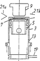
According to Fig. 1~Fig. 7 that is applicable to two-cycle engine basic role of the present invention is described.
As shown in Figure 1, in motor 1, above crank chamber 2, cylinder 3 is set liftably.This cylinder 3 is subjected to power upwards by cylinder spring 4, and piston 5 is installed in cylinder 3.Symbol 6 among the figure is cranks.
Be formed for the opening portion 7 that fluid flows on the upper-end surface of cylinder 3, the periphery of opening portion 7 becomes valve seat 8.At the valve body 9 that is provided with contact valve seat 8 when cylinder 3 rises above the valve seat 8.
Between the upper-end surface and valve body 9 of cylinder 3, form the inflow road of when cylinder 3 descends, connecting 10, flow into road 10 and is communicated with crank chamber 2 by intake channel 11, be supplied to cylinder 3 by the live gas process inflow road 10 of suction port 12 suctions of crank chamber 2.
Fig. 2 represents that piston 5 is positioned at the state of lower dead centre (crankangle is 0 degree), under this state, the following end in contact of piston 5 is arranged on the projection 14 of cylinder 3 lower ends, cylinder 3 is pushed by piston 5 and is descended, valve seat 8 separates with valve body 9, and live gas flows in the cylinder 3 through flowing into road 10, and because of relief opening 13 also in opened condition, so discharge the residual gas in the cylinder 3, be replaced by live gas in the cylinder 3.
Fig. 3 represents that crankangle is the state of 60 degree, and under this state, along with the rising of piston, cylinder 3 rises by the elastic force of cylinder spring 4, valve seat 8 contact valve bodies 9, and opening portion 7 is closed, and relief opening 13 is still opened.
Fig. 4 represents that crankangle is the state of 85 degree, and relief opening 13 is closed by piston 5, enters compression process in the cylinder.
In this compression process, valve seat 8 increases along with the increase of compression with the crimp force of valve body 9.That is, cylinder 3 can lifting, and when piston rose, the masterpiece that makes progress was used on the upper-end surface of this cylinder.Thereby valve seat 8 is pressed on the valve body 9 that is fixed.
Therefore, the area of opening portion 7 increases, and by simple valve arrangement, can prevent that the compressed fluid in the cylinder from leaking.
Fig. 5 represents that crankangle is the state of 180 degree, lights a fire near the upper dead center of piston.By the pressure that gas produced of ignition, piston is descended, and the power that makes progress act on the cylinder as described above, so kept the state of valve seat crimping valve body.Opening portion 7 is being opened always, and up to continuing to descend along with piston, relief opening 13 is opened (the expression crankangle is Fig. 6 of the state of 280 degree), and combustion gas is discharged from and cylinder is depressed by piston.
Fig. 7 represents that crankangle is the state of 315 degree, and the projection 14 of piston 5 contact cylinders 3 bottoms is depressed cylinder.At this moment, valve seat 8 separates with valve body 9, and opening portion 7 is opened, and by compression live gas flows in crank chamber, returns the state of Fig. 2.
Fig. 8~Figure 11 is the example that is suitable for two-cycle engine.
As shown in Figure 8, in motor 1, above crank chamber 2, cylinder 3 is set liftably.Cylinder 3 bears elastic force up by cylinder spring 4.In addition, the lower end of cylinder 3 touches the projection 15 of engine body when descending, and cylinder 3 is reduced to the required degree of relief opening 13 of opening.Piston 5 is installed in cylinder 3, and it is stressed up by the piston spring 16 that is bearing in cylinder 3 lower ends.Symbol 6 among the figure is cranks.
Between the upper-end surface and valve body 9 of aforementioned cylinder 3, formed the inflow road of when cylinder 3 descends, opening 10, flow into road 10 and is communicated with crank chamber 2 by intake channel 11, the live gas process inflow road 10 that is sucked by the suction port 12 of crank chamber 2 is supplied to cylinder 3.
Described piston spring 16 is more powerful than cylinder spring 4, and during piston spring 16 elongations, piston 5 is closed relief opening 13.
Fig. 8 represents that piston 5 is positioned at the state of lower dead centre (crankangle is 0 degree), and under this state, piston spring 16 is compressed, and cylinder 3 is descended by piston 5 with pushing, and valve seat 8 separates with valve body 9.Therefore, live gas flows in the cylinder 3 through flowing into road 10, and because of relief opening 13 also in opened condition, so the residual gass in the cylinder 3 are discharged from, cylinder 3 is interior to be replaced by live gas.
Fig. 9 represents that crankangle is the state of 60 degree, and under this state, though piston rises, cylinder 3 does not rise because of the power pressurized ground of piston spring 16.Thereby opening portion 7 stays open state, and relief opening 13 is blocked by piston 5.Therefore, after relief opening 13 is closed, continue to flow into, promptly carry out so-called inertia supercharging and flow into from the live gas of opening portion 7.
Figure 10 represents that crankangle is the states of 85 degree, and when piston 5 continues to rise and during piston spring 16 elongations, the power of cylinder spring 4 has surpassed the power of piston spring 16, cylinder 3 rises, valve seat 8 contact valve bodies 9, and opening portion 7 is closed, and enters compression process in the cylinder.
In this compression process, valve seat 8 increases and increases along with compression with the crimp force of valve body 9.In other words, cylinder 3 can lifting, and when piston rose, the masterpiece that makes progress was used for the upper-end surface of cylinder.Therefore, valve seat 8 is pressed on the valve body 9 that is fixed.
Therefore, even if the area of opening portion 7 increases, also can prevent to leak by simple structure.
Figure 11 represents that crankangle is the state of 180 degree, lights a fire near the upper dead center of piston.By the pressure that gas produced of ignition, piston descends, because of the power that makes progress acts on the cylinder as described above, so kept the state of valve seat crimping valve body.Opening portion 7 is being closed always, and up to continuing to descend along with piston, relief opening 13 is opened, and combustion gas is discharged from and cylinder is depressed by piston.
When piston 5 continued to reduce, the projection 15 of the following end in contact body of the cylinder of being depressed by piston spring 16 3 was so the state of Fig. 8 is returned in the decline of compression piston spring 16 limits, piston 5 limit.
In above-mentioned compression process, the area of opening portion 7 is less than the area of plane of piston 5, so, the responsive to axial force of cylinder that is equivalent to this area difference is on the direction that promotes valve, and worthwhile with the power that makes progress that obtains by the differing from of power of cylinder spring 4 and piston spring 16, therefore, inner cylinder pressure is high more, the power of valve seat crimping valve body is big more, and the pressure of pressurized gas and combustion gas subsequently can not leak.
In addition, in the above-described embodiment, force down cylinder 3 and have only piston 5 to rise, so as shown in Figure 9, under relief opening 13 closing state, can continue to flow into, thereby improve inflow efficient by the effect of piston spring 16.
Description of drawings
Fig. 1 is the sectional view of explanation working principle of the present invention.
Fig. 2 is that its crankangle of expression is the explanatory drawing of the state of 0 degree.
Fig. 3 is that its crankangle of expression is the explanatory drawing of the state of 60 degree.
Fig. 4 is that its crankangle of expression is the explanatory drawing of the state of 85 degree.
Fig. 5 is that its crankangle of expression is the explanatory drawing of the state of 180 degree.
Fig. 6 is that its crankangle of expression is the explanatory drawing of the state of 280 degree.
Fig. 7 is that its crankangle of expression is the explanatory drawing of the state of 315 degree.
Fig. 8 is the sectional view of best mode for carrying out the invention 1.
Fig. 9 is that its crankangle of expression is the explanatory drawing of the state of 60 degree.
Figure 10 is that its crankangle of expression is the explanatory drawing of the state of 85 degree.
Figure 11 is that its crankangle of expression is the explanatory drawing of the state of 180 degree.
Figure 12 is the sectional view of expression best mode for carrying out the invention 2.
Figure 13 is that its crankangle of expression is the explanatory drawing of the state of 75 degree.
Figure 14 is that its crankangle of expression is the explanatory drawing of the state of 180 degree.
Crankangle when Figure 15 is the expression misfire is the explanatory drawing of the state of 300 degree.
Figure 16 is the sectional view of another example of expression best mode for carrying out the invention 2.
Figure 17 is the sectional view of expression preferred forms 3 of the present invention.
Figure 18 is that its crankangle of expression is the explanatory drawing of the state of 180 degree.
Figure 19 is that its crankangle of expression is the explanatory drawing of the state of 360 degree.
Figure 20 is that its crankangle of expression is the explanatory drawing of the state of 380 degree.
Figure 21 is that its crankangle of expression is the explanatory drawing of the state of 540 degree.
Figure 22 is that its crankangle of expression is the explanatory drawing of the state of 710 degree.
Figure 23 is the sectional view of expression best mode for carrying out the invention 4.
Figure 24 is the sectional view of its rotary valve.
Figure 25 is that its crankangle of expression is the explanatory drawing of the state of 710 degree.
Figure 26 is the sectional view of the continuous action device of its rotary valve of expression.
Figure 27 is the sectional view of expression best mode for carrying out the invention 5.
Figure 28 is that its crankangle of expression is the explanatory drawing of the state of 380 degree.
Figure 29 is that its crankangle of expression is the explanatory drawing of the state of 710 degree.
Figure 30 is that the crankangle of other structure of expression switching valve is the explanatory drawing of 0 degree.
Figure 31 is that its crankangle of expression is the explanatory drawing of the state of 710 degree.
Figure 32 is the sectional view of the example of expression lock pin control gear.
Figure 33 is the sectional view of expression best mode for carrying out the invention 6.
Figure 34 is that its crankangle of expression is the explanatory drawing of the state of 37 degree.
Figure 35 is that its crankangle of expression is the explanatory drawing of the state of 59 degree.
Figure 36 is that its crankangle of expression is the explanatory drawing of the state of 180 degree.
Figure 37 is that its crankangle of expression is the explanatory drawing of the state of 323 degree.
Crankangle when Figure 36 is the expression misfire is the explanatory drawing of the state of 323 degree.
Figure 39 is the sectional view that expression is applicable to the example of two-cycle engine.
Figure 40 is the sectional view of expression best mode for carrying out the invention 7.
Figure 41 is that its crankangle of expression is the explanatory drawing of the state of 260 degree.
Figure 42 is that its crankangle of expression is the explanatory drawing of the state of 540 degree.
Figure 43 is that its crankangle of expression is the explanatory drawing of the state of 710 degree.
Figure 44 is the sectional view of an example of expression lock pin control.
Figure 45 is the explanatory drawing of its cam path.
Figure 46 is the sectional view of other example of expression lock pin control.
Figure 47 is the explanatory drawing of the relation of two sliding cams of expression.
Figure 48 is the explanatory drawing of the relation of two sliding cams of expression.
Figure 49 is the explanatory drawing of the relation of two sliding cams of expression.
Figure 50 is the sectional view that uses the example of U-shaped spring in the cylinder spring.
Figure 51 is the sectional view with the example of cam control cylinder.
Figure 52 is that its crankangle of expression is the explanatory drawing of the state of 180 degree.
Figure 53 is that its crankangle of expression is the explanatory drawing of the state of 230 degree.
Figure 54 is that its crankangle of expression is the explanatory drawing of the state of 360 degree.
Figure 55 is that its crankangle of expression is the explanatory drawing of the state of 405 degree.
Figure 56 is that its crankangle of expression is the explanatory drawing of the state of 540 degree (left side) and 675 degree (right side).
Figure 57 is the figure of expression cylinder position and crankangle relation.
Figure 58 is the sectional view of expression best mode for carrying out the invention 8.
Figure 59 is the sectional view of expression best mode for carrying out the invention 9.
Figure 60 is the sectional view of expression best mode for carrying out the invention 10.
Figure 61 is the sectional view of expression igniter as the mode of execution of valve body itself.
Figure 62 is the sectional view of expression best mode for carrying out the invention 11.
The sectional view of the state when Figure 63 is the expression inflow.
Figure 64 is the sectional view that the mode of execution of dbl act motor is adopted in expression.
Figure 65 is the sectional view of expression best mode for carrying out the invention 12.
Figure 66 is the sectional view of expression best mode for carrying out the invention 13.
Figure 67 is the enlarged cross section figure of this cylinder.
Figure 68 is the amplification sectional view of the cylinder of other form.
Figure 69 is the sectional view of expression best mode for carrying out the invention 14.
Figure 70 is the sectional view of the example of expression Stirling engine.
Implement preferred forms 1 of the present invention
Figure 12~Figure 14 also is the example that is suitable for two-cycle engine.
In Figure 12, above the crank chamber 2 of motor 1, liftably be provided with cylinder 3.In aforementioned cylinder 3, piston 5 is installed.Aforementioned cylinder 3 is made of casing top half 3a and following cylinder 3b, and casing top half 3a is by valve spring 17 and to lower stress, and following cylinder 3b passes through than valve spring 17 more powerful cylinder springs 4 and upwards stressed.
Between the upper-end surface and valve body 9 of aforementioned casing top half 3a, formed the inflow road of when casing top half 3a descends, opening 10, flow into road 10 and be communicated with inflow chamber 18 by intake channel 11, the live gas that is sucked by the suction port 12 that flows into chamber 18 is supplied to cylinder 3 by flowing into road 10.
Figure 12 represents that piston 5 is in the state of lower dead centre (crankangle is 0 degree), and under this state, casing top half 3a is depressed by valve spring 17, and valve seat 8 leaves valve body 9, and live gas flows into the cylinder 3 from flowing into road 10.On the other hand, the following end in contact of piston 5 is arranged on down the projection 14 on the cylinder 3b lower end, following cylinder 3b is pushed by piston 5 and descends, between casing top half 3a and following cylinder 3b, produce the gap, because of cylinder 3 and relief opening 13 are connected, so the residual gas in the cylinder 3 is discharged from, and changes to live gas in the cylinder 3.
When piston 5 rose, cylinder 3 rose by the power of cylinder spring 4, and the lower end of contact casing top half 3a, and relief opening 13 is closed.When piston 5 continues to rise, (the expression crankangle is the states of 75 degree) as shown in figure 13, casing top half 3a is pushed away on the cylinder 3b down and is risen, valve seat 8 contact valve bodies 9, and opening portion 7 is closed, and enters compression process in the cylinder.
Figure 14 represents that crankangle is the state of 180 degree, lights a fire near the upper dead center of piston.Piston descends by the pressure that gas produced of ignition, and the power that makes progress acts on the cylinder 3 as described above, so kept the state of valve seat crimping valve body.When the lower end that piston 5 continues reduction and piston 5 touched down the projection 14 of cylinder 3b, following cylinder 3b descended.When opening, combustion gas is carried out so-called venting and is discharged at a heat along with the decline of following cylinder 3b at relief opening 13.
On the other hand, when having reduced inner cylinder pressure by the combustion gas discharge, the casing top half 3a that loses power upwards along with the decline of following cylinder 3b is depressed by valve spring 17, and valve seat 8 leaves valve body 9, and opening portion 7 is open-minded.
Situation when Figure 15 represents that fuel is not lighted a fire, when not lighting a fire, inner cylinder pressure is a compression pressure, therefore, valve seat 8 is being crushed near the upper dead center of piston 5 on the valve body 9, when piston reduces, interior drops, casing top half 3a reduces with following cylinder 3b, in the time of near piston drops to lower dead centre always, just opens relief opening 13.
In described compression process, the same with first mode of execution, inner cylinder pressure is high more, and the crimp force of valve seat crimping valve body is big more, and the pressure of pressurized gas and combustion gas subsequently can not drain to the outside.
Hereinbefore, different at the optimum size of casing top half 3a, the exhaust clearance that forms between the cylinder 3b down because of operational situation, but can change the control casing top half the decline amount of movement body end difference 15a the position and obtain best exhaust condition.
In addition, when become 0 or when being adjusted to buttoned-up status during negative pressure at inner cylinder pressure, can obtain and the same effect of Howard Gardner west motor (utilizing the two-cycle engine of the inflow of effect of easing stress in the cylinder after the exhaust).
In the above-described embodiment, solved the problem of existing two-cycle engine as described below.
(1) owing to before inlet close, closed relief opening, thus the live gas discharge reduce because can supercharging, so when improving combustion efficiency and improving, the discharge of unburned HC also reduces, and has especially improved the low speed torque performance.
(2) because inflow chamber 18 independently is set, do not utilize crank chamber 2 so flow into.Therefore, the same ground with four-circulation motor can accumulate in lubricant oil in the crank chamber, and lubricant oil can not burn together with fuel, and carbon is not attached on the spark plug and exhaust can not become blue or green cigarette.
(3) relief opening is positioned on the end of cylinder barrel portion, exhaust heat is dispersed in around the cylinder, at cylinder local temperature difference not take place on one's body originally thus, thermal distortion is little.Therefore, can improve the quality of fit of piston and piston ring, improve tightness, prevent the leakage of combustion gas and lubricant oil as much as possible.
(4) under the situation that fuel is not lighted, can suppress exhaust by the delayed exhaust mouth with opening, and the fuel pump drainage when suppressing starting, can improve starting performance.
(5) the intake and exhaust condition in the time of can regulating running automatically.In other words, when firing pressure in the running hangs down (during low-load), very fast discharge has reduced inner cylinder pressure after igniting, thus, the very fast reduction of casing top half 3a, relief opening is plugged, air inlet open, thus suppressed exhaust.On the other hand, when firing pressure is high, because of the time of igniting final vacuum before pressing in reducing long, so postponed the decline of casing top half.Therefore, relief opening open time lengthening, more effectively carry out exhaust.
(6) cancellation pump chamber is installed compressor etc. by alternate manner in the inflow side, dwindled the diameter of body, can form many inflators motor.
Figure 16 is illustrated in other mode of execution that does not pass through crank chamber ground scavenging in the two-cycle engine.
In other words, film 66 is set in crank chamber 2, in a side pump chamber 67 is set, intake channel 68 is communicated with pump chamber 67.
In this structure, the variation in pressure that produces by the lifting along with piston 5 and cylinder 3 drives film 66 and obtains pump power, and ambient atmos flows into through intake channel 68, carries out scavenging.Other structure, effect are the same with the example of Figure 12~Figure 15.
Here, because cylinder and piston one lifting have improved the compression ratio in crank chamber space so the cylinder peripheral part adds piston diameter, so pump power has improved, scavenging efficiency has improved.Implement preferred forms 2 of the present invention
Figure 17~Figure 22 is the example that is suitable for four-circulation motor.To the incomplete structure the same with said structure explanation.
Above cylinder 3, offered suction port 12 and relief opening 22 and on these gas ports, be provided with one- way valve 21a, 21b respectively.Variation opens and closes these one-way valves according to inner cylinder pressure.
Hereinbefore, be that piston 5 is on the lower dead centre under the state of 0 degree in as shown in figure 17 crankangle, lock pin 19 is locked on the cylinder 3, and cylinder 3 is positioned at the below, and opening portion 7 is opened.And two one- way valve 21a, 21b close.
When piston 5 is risen, opened the one-way valve 21b of exhaust side, the gas in the cylinder 3 is discharged from (is Figure 18 of the state of 180 degree referring to the expression crankangle).
Subsequently, when reducing piston 5, the one-way valve 21a of inflow side opens, and the one-way valve 21b of exhaust side closes, and live gas enters in the cylinder 3.
As shown in figure 19, when crankangle was spent near 360, cylinder 3 was depressed by the power of piston spring 16 with overcoming the cylinder spring, and under the effect of continuous action device, the locking by lock pin 19 of cylinder 3 has been disengaged.
As represent that crankangle is the shown in Figure 20 of 380 states of spending, under the state that cylinder 3 is unclamped by lock pin 19, piston rises, when the power of piston spring 16 promotion cylinders 3 weakens, cylinder 3 rises by the power of steam-cylinder piston 4, valve seat 8 contact valve bodies 9, and opening portion 7 is closed.At this moment, these two one- way valve 21a, 21b close, and enter compression process, near upper dead center to fuel ignition.
When inner cylinder pressure rose because of fuel ignition, piston 5 was depressed.When piston 5 passed through the relief opening 13 of cylinders 3, gas was discharged from from relief opening 13 in the cylinder, and inner cylinder pressure sharply reduces.
When inner cylinder pressure reduced, because of the power that makes progress of cylinder 3 reduces, so piston spring 16 elongations, cylinder 3 was depressed by piston spring 16.Therefore, be 0 when spending in next circuit crankangle, lock pin 19 is locked on the cylinder 3, and cylinder 3 is fixed.
In this embodiment, combustion gas is discharged from from the relief opening 13 of cylinder, and this exhaust with the scavenging that is used for carrying out from the relief opening 22 of cylinder top is different.Therefore, high-temperature gas is without the valve portion of cylinder upper, and the heating of the high temperature of this part is few, and the durability of valve, reliability improve.In addition, the enough simple one-way valves of transformation energy in air outlet flue and inflow road come corresponding and work automatically naturally, so do not need mechanical actuation device.Implement preferred forms 3 of the present invention
Figure 23~mode of execution shown in Figure 26 is to replace one-way valve 21a, the 21b of mode of execution 3 with rotary valve 23, and relief opening is not set on the perisporium of cylinder 3, and exhaust is undertaken by the relief opening 22 of cylinder top fully.
Owing on the cylinder perisporium, do not have relief opening, so do not need piston spring.
The control gear of above-mentioned rotary valve and crank 6 mechanical interlocks (with reference to Figure 26) or carry out automatically controlled.
In this embodiment, in second circulation, in the time of near piston is positioned at upper dead center, gas is lighted, and when inner cylinder pressure increased, piston 5 reduced without a break, and cylinder 3 is depressed.Along with cylinder reduces, opening portion 7 is opened, the pressurized gas discharge (seeing Figure 25) of being taken a breath.
In this embodiment, when switching inflow and exhaust, adopt under the situation of rotary valve, discharge, also be difficult to be subjected to heat affecting even if carry out combustion gas from the rotary valve top.And the rotary valve 23 of this mode of execution only switch fluids flows to, so the smooth and easy littlely rotation of load.
In mode of execution shown in Figure 26, do not have the lock pin 19 that is locked on cylinder 3 sidewalls is set, but control the rising of cylinder 3 by the rotation of rotary valve 23.
In other words, pin 19a is upwards given prominence on the end face of cylinder 3, on the other hand, below rotary valve 23 body 23a, be provided with groove (not shown) corresponding to pin 19a.Because of the angle of swing of rotary valve 23 and the rising limit position of cylinder 3 correspond to each other, so add deep trouth according to the angle of swing that allows cylinder 3 to rise, allow cylinder to rise thus, the angle of swing that should be positioned at the below according to cylinder 3 reduces groove depth (or not establishing groove), thus, the lifting position of control cylinder.
In addition, even if, also can similarly control pin 19a being set on the rotary valve 23 and on cylinder 3, groove being set.Implement preferred forms 4 of the present invention
Figure 27~mode of execution shown in Figure 29 is other example that is also carried out the ventilation discharge of combustion gas by opening portion 7.
In Figure 27 (crankangle is 0 degree), above cylinder 3, be provided with the suction port 12 of band one-way valve 21a, the relief opening 22 of band one-way valve 21b, the fuel gas exhaust mouth 22a that below aforementioned relief opening 22, forms.On aforementioned fuel gas exhaust mouth 22a, but free lifting ground the cross section be installed become L shaped annular switching valve 24, switching valve 24 is by valve spring 25 and to lower stress, the upper-end surface of the bottom surface of switching valve 24 contact cylinder 3.So set this contact force (intensity of valve spring), promptly under the state of Figure 29 described later, switching valve 24 is upwards pushed away by the pressure in the valve casing, and fuel gas exhaust mouth 22a is opened.
In this embodiment, in first circulation, cylinder 3 is fixed by lock pin 19, thereby can not rise, so the power of switching valve 24 by valve spring 25 is depressed, common, fuel gas exhaust mouth 22a closes.
In second circulation, the locking of lock pin 19 is disengaged, cylinder 3 rises (see Table and show that crankangle is Figure 28 of the state of 380 degree), so opening portion 7 is closed, is compressed in the cylinder, near the upper dead center of piston, gas is lighted a fire, the pressure that causes by igniting increases, and piston 5 reduces at a heat, and cylinder 3 is depressed, thus, opening portion 7 is opened.At this moment, gaseous-pressure through opening portion 7 act on switching valve 24 below, and top switching valve 24 upwards, so the relief opening 22a of combustion gas opens, combustion gas is discharged from (being Figure 29 of 710 states of spending referring to crankangle) through relief opening 22a.
Figure 30, Figure 31 represent other structure of described switching valve.
Here, switching valve 24 is circular disks and passes through valve spring 25 to lower stress.Therefore, during the below of the position, cylinder upper-end surface when fuel gas exhaust mouth 22a is arranged on cylinder 3 and descends, in as shown in figure 30 crankangle is under the state of 0 degree, utilizes the switching valve 24 that contacts the cylinder upper-end surface by the power of valve spring 25, has blocked between cylinder openings portion 7 and the relief opening 22a.
In this structure, when voltage rise is high in the cylinder that is caused by burning, switching valve 24 by on push away, the opening portion of cylinder 7 communicates with each other with relief opening 22a, this structure with Figure 27 the same (is Figure 31 of 710 states of spending referring to the expression crankangle).
According to this mode of execution, the required action of conversion of the intake and exhaust of piston valve, one-way valve etc. is carried out automatically by air pressure fully, does not therefore need the moment control mechanism of intake and exhaust.
Figure 32 is illustrated in the example of the control gear of the lock pin 19 of fixed cylinder in the mode of execution of above-mentioned four-circulation motor.
In other words, make lock pin 19 contacts and leave cylinder 3 by solenoid 26.In this case, thus produce electrical signal and connection/closed solenoid with the position of sensor crank 6.
Figure 33~Figure 43 is dual valve arrangement, and Figure 33~Figure 39 is the example that is suitable for two-cycle engine, and Figure 40~Figure 43 is the example that is suitable for four-circulation motor.
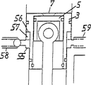
In any one example, directly do not make the valve seat 8 contact valve bodies 9 of cylinder, annular intervening valve 27 is set between the two, between the top and valve body of intervening valve 27 and below intervening valve and between the valve seat 8, formed runner respectively.Implement preferred forms 5 of the present invention
Be applicable among Figure 33 of example of two-cycle engine in expression, between cylinder 3 and valve body 9, be provided with the valve seat 8 of the opening portion 7 of bottom surface contact cylinder 3, and the intervening valve 27 of top contact valve body 9.When intervening valve 27 contact valve seats 8 and valve body contact intervening valve 27, the opening portion 7 of cylinder 3 is closed.Subsequently, intervening valve 27 is by valve spring 28 and to lower stress.
In addition, cylinder 3 has been closed relief opening 22 when rising.
Here, when piston 5 is in lower dead centre (Figure 33), intervening valve 27 is pressed down by valve spring 28, has formed the inflow runner on intervening valve 27 and between the valve body 9.And between the bottom surface and valve seat 8 of intervening valve 27, formed grate flow channel.
Therefore, the mixed gas by scavenging pump (not shown) force feed enters cylinder 3 by suction port 12 and contact piston 5 reverses, and is discharged from from relief opening 22 subsequently, carries out scavenging thus in the countercylinder.
Improve scavenge effect by the most effective Xiu Nilei (シ ュ ニ ュ one レ) mode of mixed airflow of utilizing, evaluation result is that efficient is than way flow moment.
When piston 5 rose, cylinder 3 rose by the power of cylinder spring 4, and intervening valve 27 contact valve seats 8 are plugged between the opening portion 7 of cylinder 3 and the relief opening 22, continue only to flow into (is Figure 34 of the state of 37 degree referring to the expression crankangle).
Along with piston 5 continues to rise, cylinder 3 continues to rise, and intervening valve 27 is upwards pushed away, intervening valve 27 contact valve bodies 9, and opening portion 7 is closed, and enters compression process (is Figure 35 of the state of 59 degree referring to crankangle).
Subsequently, near the upper dead center of piston 5, light gas (seeing Figure 36).
When by increasing along with the inner cylinder pressure of gaseous combustion when depressing piston 5 and reducing cylinder 3, intervening valve 27 overcomes valve spring 28 by inner cylinder pressure upwards to be pushed away, and opens air outlet flue and discharges combustion gas (is Figure 37 of the state of 323 degree referring to the expression crankangle) at a heat.
Hereinbefore, under situation not, because of inner cylinder pressure does not increase to fuel ignition, so intervening valve 27 and cylinder 3 reduce (is Figure 38 of the state of 323 degree referring to the expression crankangle) together, open suction port 12 earlier, when cylinder continued to reduce, relief opening 22 was opened.
Figure 39 is the example that above-mentioned valve arrangement is used to crank chamber compression-type two-cycle engine.
This mode of execution is arranged on except suction port inside and outside the crank chamber, and is the same with above-mentioned mode of execution.
In these mode of executions, do not resemble and cylinder is cut apart up and down the mode of execution 2, also on the cylinder perisporium, relief opening is set, can obtain to finish the two-cycle engine of intake and exhaust.
In addition, when heavy fresh cold air directly over cylinder during the contact piston end face, when obtaining cooling effect, counter-rotating is also discharged residual combustion gas from relief opening with concentric circle with overlapping, thus, obtains and the similar scavenging method newly of counter-rotative type ventilation.Implement preferred forms 6 of the present invention
Figure 40~Figure 43 is the example that is suitable for four-circulation motor.On intervening valve 27, form the runner 27 that has only permission one-way valve towards the inner side surface inflow here, from top, in first circulation, prevent on the cylinder 3 that it from rising thereby lock pin 19 is locked in, and the receiver 3c of cylinder 3 there is clearance, in first circulation, cylinder also can rise slightly.
Here, when piston 5 when lower dead centre (Figure 40) rises, the head pressure of intervening valve 27 by residual gas overcomes valve spring 28 and rises, and opened relief opening 22, and discharged residual gas.
When the piston 5 that arrives upper dead center is descended, intervening valve 27 reduces and contacts the upper-end surface of cylinder 3 by valve spring 28, relief opening 22 is closed, on the other hand, be switched between suction port 12, runner 27a, the opening portion 7, live gas flows in the cylinder 3 and (sees Table and show that crankangle is Figure 41 of the state of 260 degree).
In second circulation, when cylinder 3 rose, intervening valve 27 was upwards pushed away, and the opening portion 7 of cylinder is closed, and gas is compressed in the cylinder, near the upper dead center of piston 5 gas is lighted a fire.Increase by the pressure that causes by the gas igniting, piston 5 is depressed, piston forces down cylinder 3 near lower dead centre, so produced the gap between the upper-end surface of intervening valve 27 and cylinder 3, combustion gas is discharged from (is Figure 43 of the state of 710 degree referring to the expression crankangle) through this gap from relief opening 22.
Figure 44, Figure 45 represent the example by cam gear control lock pin, and they are the examples that can be applicable to the above-mentioned mode of execution that adopts lock pin.
In Figure 44, the lock pin 19 of bottom that is contained in cylinder 3 is by spring 29 and stressed on projected direction, and it has arrived and has been arranged at its front end and is fixed in the cam path 31 of the block 30 on the sidewall of piston 5.
Cam path 31 is such with the position relation of lock pin 19, and the crankangle that is positioned at lower dead centre when piston 5 is 0 when spending, and lock pin is positioned at the symbol a place of Figure 45, when crankangle is 180 when spending, be positioned at symbol b place, allow cylinder 3 to rise slightly, when crankangle is 360 when spending, be positioned at symbol c place, cylinder 3 descends, when crankangle surpasses 360 degree, enters second circulation time, move to d, cylinder 3 rises, and when crankangle is spent above 540, shifts to a.
In order to obtain above-mentioned action, cam path to a earth tilt, deeply inserts at each transition point a, b, c, d place from a to b, from b to c, from c to d, from d, can not oppositely move.
Figure 46~Figure 49 represents to make other structure of cylinder 3 liftings.
That is, on vertical axle 61 two sliding cams 62,63 with serrated end face 62a, 63a have been installed, the sleeve 65 with the ring rib 64 that is equivalent to lock pin is fixed on the sliding cam 63 in the outside, and raised line 64 interlockings are in the groove of cylinder.
Hereinbefore, the contact position of the contact serrated end face of these two sliding cams changes by moving of sliding cam.Here, if form relative sawtooth end face like this, promptly sliding cam 63 is in low position and is on the high position in second circulation in first circulation of piston, then controls the height of cylinders by raised line 64.
Figure 50 represents other example of cylinder spring 4, and it can suitably be used for the respective embodiments described above.
That is, as cylinder spring 4, the one end is installed on the crank 6 the U-shaped spring, and the other end is crimped on the lower end of cylinder 3, makes cylinder 3 up stressed.
In Figure 50, lock pin 19 is by spring 29 and stressed towards the cylinder direction, and controls the advance and retreat of lock pin 19 by brake cam 32.
Here, the width of receiver 3c that is formed at the lock pin on the cylinder 3 is bigger than the size of lock pin, so there is play on above-below direction.Owing to there is play, so when exhaust, cylinder rises slightly with piston 5, can reduce the gap between piston-top surface and the valve body 9 as much as possible, thus, can improve exhaust effect.
But when piston 5 contact cylinder end faces, lock pin 19 probably can be damaged, therefore makes both determine described play amount (groove width) non-contiguously.
Figure 51 represents not utilize moving of piston direct control cylinder, but by cam-operated.Except structure shown below, can utilize known mechanical structures such as suitable cam structure, clutch and coupling to operate cylinder or lock pin.
In Figure 51, be provided with retention tab 33 in the underpart of cylinder 3, the front end of control cam 34 is installed on the retention tab 33.
Except machinery control, described control cam also can be automatically controlled.
Like this, if, then can set the position of crankangle and cylinder arbitrarily by controlling the lifting of cam control cylinder.
In other words, when by control cam control cylinder position, the lower end that can make cylinder than the lower dead centre of piston more by descending.Therefore, can constitute the switching valve of intake and exhaust simply.
That is, in Figure 51, be provided with relief opening 22 on the top of engine body, valve body 9 is provided with suction port 12 near the lower end of relief opening 22 below valve body 9.It is the switching valve 24 of circular disk that the projection 15 of the lower end by being positioned at relief opening 22 supports.
When piston 5 is 0 when spending (Figure 51) in the crankangle of lower dead centre, cylinder 3 reduces, and switching valve 24 cuts out, and suction port 12 is closed by the perisporium of cylinder 3.
When piston 5 rose, cylinder 3 rose slightly so that allow piston 5 to rise as much as possible, is parked in the bottom.At this moment, rise by piston, discharge residual gas, the switching valve come-up is opened relief opening 22 (Figure 52).
Then, in piston 5 reductions, when fluid enters, cylinder 3 descends, and its upper end drops to suction port 12 belows, and suction port 12 is open-minded, and live gas flows in the cylinder 3.At this moment, inner cylinder pressure is low, thereby 24 reductions of aforementioned switching valve, and relief opening 22 is closed (Figure 53 and the expression crankangle that referring to the expression crankangle are the states of 230 degree are Figure 54 of the states of 360 degree).
When entering second circulation time, when the cylinder rising, closing suction port 12,, opening portion 7 closes relief opening 22 thereby being closed, entered compression process (is Figure 55 of the states of 405 degree referring to the expression crankangle).Subsequently, crankangle be 540 degree near, fire fuel, inner cylinder pressure increases, piston is depressed, switching valve 24 rises by exhaust pressure, and opens relief opening 22.Subsequently, cylinder 3 descends, and returning crankangle is the state of 0 degree.
Figure 57 represents the action of said cylinder lower end position and the relation of degree in crank angle, and A is exhaust, and B flows into, and C is compression, and D is burning.Implement preferred forms 7 of the present invention
Shown in Figure 58, by plugging auxiliary valve body 35, with runner be divided into be opened on auxiliary valve body 35 tops and suck the inflow road 10a of rich mixture and be opened on the below of auxiliary valve body 35 and suck the inflow road 10b of weak mixture.Constituted auxiliary valve body 35 and above valve body 9 between blocked the valve body of the present invention of cylinder openings portion 7.
On engine body, be provided with the bearing 36 of auxiliary valve body 35, between the upper-end surface and valve body 9 of cylinder 3, plugged auxiliary valve body 35, on auxiliary valve body 35, be provided with vent 37.In addition, on aforementioned valve body 39, igniter 38 has been installed.
In addition, relevant with the lifting of cylinder and piston concrete structure can suitably adopt the structure shown in the above-mentioned mode of execution.
Here, when cylinder 3 rose, the valve seat 8 contact auxiliary valve bodies 35 of cylinder rose it, and end face contact valve body 9 ground of auxiliary valve body 35 have sealed cylinder internal.
Here, because the top of auxiliary valve body 35 links to each other with the inflow road 10a that sucks rich mixture, thus replenish the rich mixture of igniting easily for the top of auxiliary valve body 35, thereby light a fire easily.
Therefore, also can enough rarefied gas stably light a fire, thereby can suppress the generation of NOx and other harmful gas.Implement preferred forms 8 of the present invention
Figure 59 is the example that the present invention is applicable to the fuel-direct-jetting type motor resemble the diesel engine, has wherein installed in valve body 9 direct fuel injection is gone into nozzle in the cylinder.In this embodiment, also can suitably adopt the lifting structure of cylinder.
In Figure 59, igniter 38 and fuel nozzle 39 are installed on the valve body 9.
Figure 60 is other example of the fuel nozzle 39 of an inside direct jet type engine.Along with the lifting of valve body 9, the plunger 40 of fuel nozzle is moved up and down, do not need the continuous action device in Figure 59 example.
In other words, the plunger 40 sliding upsides that are embedded in valve body 9 contact on the end difference 42 of valve bodies 9 end difference 43 of plunger 40, and aforementioned valve body 9 passes through valve spring 17 to lower stress.
When having such structure, when cylinder 3 reduced, valve body descended, and plunger 40 also decreases, and one-way valve 41 is closed, so do not spray fuel.When upwards pushing away when cylinder 3 risings and with valve body 9, plunger 40 also rises, and one-way valve opens when producing fuel pressure is through being arranged at the spray orifice ejection fuel on the valve body 9.
Also can resemble Figure 59 set-point firearm 38.
Shown in above-mentioned Figure 58~Figure 60, in the present invention because the area of valve body 9 is big, thus can be on valve body 9 mounting points firearm and fuel nozzle etc.
Figure 61 is the example of igniter as valve body itself.
In other words, igniter 38 lower end surface 38a own are made the valve body that has corresponding to the size shape of valve seat 8.
In the present invention, if the inner cylinder pressure height, the crimp force height of valve seat and valve body then, thus, valve seat and valve body to be close to required precision low.Therefore, need only the shape of the shape of existing spark plug front end being made respective valve seat, just can fully use as valve body ground.Therefore, even if the little model cylinder of path cylinder also can obtain practical motor in precision machining ground.Implement preferred forms 9 of the present invention
Figure 62, Figure 63 are the examples that the present invention is applicable to compressed fluid motor (external-combustion engine).In addition, except that steam, comprise various compressed fluids such as compressed oil, pressurized air as compressed fluid.
In the drawings, on the lid 44 of engine body, be provided with compressed fluid suction port 45, below suction port 45, be provided with the spherical auxiliary valve body 46 of lifting.Below the valve seat 47 of auxiliary valve body 46, liftably be provided with valve body 9, valve body 9 by valve spring 17 towards lower stress.
On valve body 9, thus be provided be communicated with its up and down gas pipeline and when valve body 9 risings on lift the projection 48 that described auxiliary valve body 46 is opened valve.
In addition, cylinder 3 passes through cylinder spring 4 towards lower stress.
In this embodiment, in Figure 62, piston 5 is positioned at lower dead centre, and cylinder 3 and piston reduce together.Thus, the opening portion 7 of cylinder 3 is opened, and the fluid in the cylinder is discharged from from relief opening 22.
At this moment, because valve body 9 reduces, spherical auxiliary valve body 46 descends, and touches valve seat, and auxiliary valve seat 47 is closed, so compressed fluid can't flow into.
Thus, piston 5 is shifted to upper dead center by the effect and the inertia of uneven weight.
Figure 63 represents that piston is positioned at the state of upper dead center.At this moment, along with the rising of piston 5, cylinder 3 overcomes the effect of cylinder spring 4 and rises, and the valve seat 8 contact valve bodies 9 of cylinder 3 have been closed opening portion 7.Cylinder 3 also has been disconnected with relief opening 22.Meanwhile, thereby rising spherical auxiliary valve body 46, the projection 48 of valve body 9 lifts off a seat 8, so open valve.
Thus, compressed fluid enters cylinder 3 through the runner that is arranged in the valve body 9, and forces down piston 5.
When aforementioned flow of compressed fluid is fashionable, when the interior pressure of cylinder 3 increased, the pressure that cylinder 3 is pressed to valve body 1 also increased, thus with the same ground of each mode of execution of above-mentioned motor, do not worry the interior compressed fluid leakage of cylinder.
When the effect by compressed fluid descended piston, cylinder 3 was subjected to piston to promote the state that ground descends and returns Figure 62.
Projection 48 also can be arranged on cylinder or the piston.
According to this mode of execution, before near the piston arrives lower dead centre, compressed fluid continues to flow in the cylinder 3.Therefore, the sealing state along with further improve valve as the increase of following inner cylinder pressure of feature of the present invention can make the pressure of compressed fluid act on the piston as far as possible for a long time, obtains the high external-combustion engine of output thereby can reduce energy loss ground.
As mentioned above, according to this structure, from seal the opening portion 7 of cylinder in front of the piston upper dead center to the lower dead centre front, compressed fluid flows in the cylinder, and during the period, compressed fluid acts on the piston.Thus, if surpass in many inflators type cylinder of 3 and removal inner cylinder pressure when running stops at inflator, make lifting that cylinder do not leave valve body 9 ground control cylinder (for example, be suitable for cylinder lifting control device shown in Figure 46), then can only utilize the flow control of compressed fluid to carry out having determined usually the starting that turns to, thereby, can obtain to reduce the big external-combustion engine of torque of energy loss, also can be used to from now on pressurized air etc. is in the nuisanceless engine for automobile etc. of energy.
Figure 64 is the example that the valve arrangement of Figure 62, Figure 63 is applicable to dbl act motor (generator).
In other words, form valve seat 8 on the two ends of cylinder 3, make valve body 9 near each valve seat 8, spherical auxiliary valve body 46 opens and closes by moving of valve body 9.
Double-head piston 5 has been installed in cylinder 3, at piston space magnet 71 has been installed, magnet 71 moves back and forth by moving of piston.In the arranged outside of cylinder 3 magnetic circuit and coil 72, in coil, produce voltage by moving of piston.
In this generator, the action of valve is the same with the valve events of above-mentioned Figure 62, Figure 63.Implement preferred forms 10 of the present invention
The external-combustion engine of representing with symbol A in the left side of Figure 65 is the machine corresponding to claim 8, and it is provided with valve seat 8 on piston 5.
In Figure 65, on engine body, but free lifting cylinder 3 is installed.Cylinder 3 links to each other with crank 6, and its elevating movement is transformed into and rotatablely moves and be output.
On described engine body, be provided with compressed fluid suction port 45, valve body 9 thereunder is installed.Valve body 9 is that top is closed the cylindrical shell that plate 9a blocks, in its underpart contact piston valve seat 8, by valve spring 17 towards lower stress.Therefore, the contact of the periphery of shut 9a is formed at the valve body fitting seat 50 on the engine body, when piston descends, and its contact valve body fitting seat 50.In addition, on the perisporium of aforementioned valve body 9, offered exhaust opening portion 51.When valve body reduces, be communicated with the relief opening 22 of engine body.
Here, when cylinder 3 was positioned at lower dead centre as shown in figure, piston 5 also was positioned at the below.Therefore, valve body 9 reduces, and valve cuts out by the power of valve spring 17, thereby compressed fluid can't flow into, and the cylinder inner fluid is discharged from through opening portion 51, the relief opening 22 of valve body 9 and cylinder 3 rises because of uneven weight and inertia.
When cylinder 3 rose, piston 5 also rose, and valve seat 8 contact valve bodies 9 upwards push away valve body 9.When valve body 9 rose, the shut 9a of valve body 9 left valve body fitting seat 50, and suction port 45 is communicated with cylinder 3, and compressed fluid flows in the cylinder 3.
Along with compressed fluid flows into, cylinder 3 is depressed, thereby the effect of piston 5 by piston spring 16 be depressed, and separates with valve body 9.When piston 5 descended, valve body 9 reduced by the effect of valve spring 17, thus at opening portion 51 with when relief opening 22 is communicated with, opening portion 51 is communicated with cylinder 3, the interior fluid of cylinder is discharged from and returns the state of figure.
According to this mode of execution, this moves cylinder in piston stroke, thereby, compare with the situation that crank links to each other with piston, under the equirotal situation of cylinder itself, the guiding distance can prolong.Therefore, vibration reduces, and this especially is favourable in diameter cylinder.
In addition, do not flow to extraneous runner between compressed fluid suction port 45 and valve body fitting seat 50 and in the crank chamber, therefore, when flowing into increase cylinder 3 internal pressures by compressed fluid, piston 5 is pushed upwardly by pressing in the cylinder, so, valve seat 8 compresses valve body 9 more, has improved tightness.Therefore, compressed fluid drains to the outer worry of cylinder such as crank chamber and reduces, and can obtain the few external-combustion engine of energy loss by simple structure.
Like this, because energy loss is few, so also be effective to utilizing small pressure reduction, utilizing the small-scale generating of wave energy and volcanic eruption gas etc.Implement preferred forms 11 of the present invention
The mode of execution of representing with symbol B on the right side of Figure 65 is the example that the present invention is applicable to pump, carries out constituting this mode of execution with above-mentioned motor A opposite action ground.That is, relief opening 22 is arranged on the top of the pump housing, and its below is provided with suction port 45.Therefore, valve body 9 is for there being bottomless drum shape, its bottom opening and the spherical auxiliary valve body 46 that opens and closes opening portion 54 is housed.
Here, be under the state of lower dead centre at as shown in the figure cylinder 3, piston 5 is stressed up by piston spring 16, thus, contact valve body 9, and auxiliary valve body 46 also reduces, cylinder 3 inside are hedged off from the outer world, and cylinder 3 is by uneven weight and inertia rising.
Along with cylinder 3 rises, when valve 5 is pushed to by the hydrodynamic pressure cylinder 3 in, on lift auxiliary valve body 46, opening portion 54 is opened, cylinder 3 interior fluids are discharged from by relief opening 22.
When discharging fluid, auxiliary valve body 46 descends, and opening portion 54 is closed.At this moment, fluid flows into through suction port 45 usually, and when hydrodynamic pressure had surpassed the elastic force of piston spring 16, piston 5 was depressed, and valve seat 8 separates with valve body 9.Therefore, suction port 45 is communicated with cylinder 3, so flow volume exists in the cylinder 3, cylinder 3 is depressed, and returns illustrated state.
This pump is because of not worrying that compressed fluid leaks into the outside in the cylinder, so even if fluid pressure difference is little also to be utilized, also can be used for air conditioning pump etc. effectively.
When shown in Figure 65, making up above-mentioned motor A and pump B, the fluid driven motor A that is heated by heater 52, thereby the used fluid of motor A can be introduced into pump B and make pump B work, thereby, circulation of fluid is flowed, be applicable to that effectively employing dewaters and the outer combustion-ing engine of the fluid that air is outer.Implement preferred forms 12 of the present invention
The mode of execution of Figure 66 to Figure 68 is the example that has two kinds of functions of the motor of above-mentioned mode of execution 10,11 and pump by a machine.
Shown in Figure 67, the inwall of machine itself by end difference 55 with the bottom as path, the outer wall of cylinder 3 by end difference 56 with the bottom as path, between the inwall of cylinder 3 and machine itself, formed pump chamber 57.The volume of pump chamber 57 increases when cylinder 3 rises and dwindles when it descends.Originally be provided with the passage 58,59 of pump chamber 57 and heater 52, cooler 53 on one's body at machine.
The structure of valve body 9 is the same with above-mentioned mode of execution.
Here, when piston 5 is positioned at upper dead center as shown in the figure, will push away on the valve body 9, through the cylindrical portion 9b of suction port 12, valve body openings portion 51 and valve body 9, the top of cylinder 3 is connected, and valve body openings portion 51 and relief opening 22 are closed.Therefore, the top by heater 52 heating, the intrasystem direction of flow cylinder 3 that expands and depress piston 5.When piston 5 descend and its down during the end difference of end in contact cylinder lower, cylinder 3 is depressed by piston 5 and is dropped to lower dead centre with piston 5.
When cylinder 3 descended, valve body 9 descended, and is plugged between suction port 12 and the cylinder 3, and cylinder 3 is communicated with cooler 53 by relief opening 22.The decline of cylinder 3 causes pump chamber 57 volumes to dwindle.Therefore, remaining in fluid in the pump chamber 57 is forced out and flows to heater 52 and heat from pump chamber 57.During this, piston 5 and cylinder 3 rise by uneven weight and inertia, and the volume of pump chamber 57 increases.In the process that cylinder 3 rises, valve body 9 descends, thereby the fluid that is promoted, cools down by aforementioned heated fluid flows to pump chamber 57 and returns illustrated state from cooler 53.
Shown in Figure 68, with on the contrary above-mentioned, the inwall of machine itself by end difference 55 with the bottom as major diameter, the outer wall of cylinder 3 by end difference 56 with the bottom as major diameter, between the inwall of cylinder 3 and machine itself, formed pump chamber 57.
In this structure, when cylinder 3 rose, the volume of pump chamber 57 increased, and volume dwindles when descending.Implement preferred forms 13 of the present invention
Figure 69 is the two-cycle engine by following formation cylinder 3, promptly in the upper end portion as the cylinder block 3d of cylindrical shell, the cylinder end face component 3e that is provided with opening portion 7, valve seat 8 is installed liftably.
Cylinder block 3d is fixed on the engine body.Thereby cylinder end face component 3e is installed on the cylinder body 3d airtightly, even when pressure rises, does not also lose the confidentiality of itself and cylinder block 3d.
Cylinder end face component 3e is connected with driving body 76 by bar 75.And stressed up, when piston 5 descended, it was oppressively reduced by piston driving body 76 by spring 77, and when rising, it rises by the power of spring 77.
Be positioned under the state of lower dead centre at as shown in the figure piston, driving body 76 descends, so the cylinder end face component 3e that links to each other with driving body 76 by bar 75 descends, the valve seat 8 and the valve body 9 that are formed on the cylinder end face component 3e are separated from each other, and cylinder 3 carries out scavenging communicatively with relief opening 22.
When piston 5 rose, the temporary transient and piston of driving body 76 rose together, and valve seat 8 contacts intervening valves 27, closed relief opening 13 and only continued to flow into.When piston continued to rise, cylinder end face component 3e was by top intervening valve 27 on the power of spring 77 and contact valve body 9, and so, suction port 12 also is closed, and enters compression process.Subsequently, near the upper dead center of piston fuel is lighted a fire, the inner cylinder pressure reduction is also returned shown position.
In this structure, owing to fixed cylinder block 3d, the gap that does not need cylinder to move usefulness between cylinder block and cooling water pipeline 78 exists and does not produce the advantage that cooling effectiveness reduces.
In addition, although hereinbefore the explanation be the structure of two-cycle engine, this structure is equally applicable to four-circulation motor.Also can utilize lock pin 19 grades, come lift cylinder end face parts 3e and driving body 76 by the device that makes the lifting of rise-fall type cylinder shown in the respective embodiments described above.Reference example
According to the present invention, when cylinder also when mobile together, can be simplified the structure of so-called exhaust (デ イ ス プ レ-サ-) type Stirling engine with piston.
Though the someone has proposed Stirling engine very early, Cai re-recognized for the efficient activity and the low public hazardsization of prime mover in recent years.
The discharge type Stirling engine is such: promptly the two ends of exhaust cylinder are by linking to each other by the gas of heat exchanger and the runner of other fluid, by being installed in mobile cold air or heating installation are sent in the exhaust cylinder of the exhaust pition (デ イ ス プ レ-サ-ピ ス ト Application) in the exhaust cylinder, then, from the exhaust cylinder, intrasystem gas is sent into the top of actuating cylinder, make the power piston lifting that is contained in the actuating cylinder by this gas, thereby obtain power.
Therefore, in existing discharge type Stirling engine, usually, need these two separate cylinders of exhaust cylinder and actuating cylinder and two cranks.
, by with the mobile together cylinder of piston, can drive the discharge type Stirling engine with 1 crank.Below, although fluid shows as gas form, degasification is external, also can use liquid.
In Figure 70, in the inner space of engine body, formed the minor diameter 81 that plays cylinder action in the bottom, top is large-diameter portion 82, has formed end difference 83 between minor diameter 81 and large-diameter portion 82.
And, between the lower wall of the upper wall of aforementioned large-diameter portion 82 and large-diameter portion 82, link to each other by gas flow 84, in this gas flow 84, set gradually cooler 53, heat exchanger 85, heater 52 from top to bottom, supplied cold air from the top of large-diameter portion 82 respectively, supply heating installation from its underpart.
In aforementioned minor diameter 81, but free lifting cylinder 88 is installed, in the upper end of cylinder 88, be provided with exhaust pition 89 integratedly.Central authorities at exhaust pition 89 are provided with through hole 90, are provided with retainer 88a in the inboard, underpart of cylinder 88.Therefore, total the moving up and down of exhaust pition 89 in large-diameter portion 82.
The piston ring 93 of sealing usefulness has been installed on exhaust pition 89 hereinbefore.By piston ring 93, and the large-diameter portion inwall of engine body between produced surface friction drag, even power piston 91 moves in cylinder 88, exhaust pition 89 does not but move.
The action of above-mentioned Stirling engine is as described below.
In addition, as the theoretical characteristics of Stirling engine, do not have resistance theoretically fully in airflow path 84, no matter the pressure of sealing gas how, exhaust pition pressure up and down normally equates.
In the drawings, exhaust pition 89 and power piston 91 are positioned at upper dead center position together.At this moment, the gas in the gas flow 84 is partial to heater 52 those sides, thereby the gas that is heated by heater rises the pressure in the gas flow 84.The power that is equivalent to unlifting pressure acts on the end face of power piston 91 through through hole 90, and applies downward power and make its decline on power piston 91.
When power piston 91 descends and crankangle when spending near 90, the retainer 88a of the following end in contact cylinder 88 of power piston 91, cylinder 88 and with it the exhaust pition 89 of one descend and also arrive lower dead centre together.
In addition, in the motion of power piston 91 with it in the motion of the cylinder 88 of interlock,, wait and regulate frictional force by adding braking in case of necessity in order to make both phase differences (being about 90 degree hereinbefore) not normal.
Hereinbefore, along with the reduction of exhaust pition 89, the superjacent air space of exhaust pition 89 enlarges, and following side space dwindles, and so, gas is shifted to cooler 53 sides.At this moment, heated gas is preserved heat and temperature reduction ground inflow cooler 53 in heat exchanger 85.
When intrasystem gas was cooled, the pressure in the gas flow 84 reduced, and has produced the attraction force that is equivalent to reduce pressure, and power piston 91 is attracted and rises.Thereby when crankangle was near 270 degree, the bottom surface of the last end in contact exhaust pition 89 of power piston 91 also upwards pushed away exhaust pition.
Along with exhaust pition 89 rises, gas is shifted to the heater side and is returned shown position.
In gas moved, when, storing in heat exchanger during to cooler one side from heater one sidesway, when from cooler one sidesway during to heater one side, the heat that is stored in the heat exchanger was output.Therefore, the cooling heat that adds in heat and the cooler in the heater has reduced.
Therefore, because exhaust pition and power piston are integral, so can shorten gas flow 84 as much as possible, thermal loss has also reduced.
By forming said structure, independent at present exhaust pition and the power piston that constitutes becomes one, and device has been simplified and can have been realized miniaturization.
Therefore, just can satisfy because gas flow is short and small, thus can obtain responsiveness that gas moves better, energy density Stirling engine more efficiently.The invention effect
According to the present invention, by on the little opening portion air inlet and exhaust valve being set than the diameter that is contained in the piston in the cylinder or than cylinder diameter, increase the tightness that improves valve with inner cylinder pressure, when can obtaining the high control valve unit of confidentiality by simple structure, can increase to the piston diameter limit to the opening portion area, can obtain the high motors such as engine of exhaust efficiency thus.
In addition, because valve body is at cylinder or be arranged at the pressure of control cylinder between the valve seat on the piston, so cylinder head and the packing ring between the cylinder block (fault is many) that need in existing prime mover and pump etc., see not.
In addition, in internal-combustion engine of the present invention, change the lifting distance of cylinder by the upper-lower position that makes valve body.Because the lifting distance of piston is certain, so when setting the upper dead center of cylinder high when making valve body be positioned at the top, the compression ratio in the cylinder is less, on the contrary, when setting the upper dead center of cylinder low when making valve body be positioned at the below, the compression ratio in the cylinder is bigger.That is, in engine running, change up and down compression ratio in the cylinder, can carry out the control of combustion efficiency thus by making valve body.
Industrial applicibility
As mentioned above, valve gear of the present invention can be by simple structure with gas piston linkage open Close the air inlet and exhaust valve of cylinder, and can amass and high-efficiency operation by increasing valve face, it can be wide Be applicable to internal combustion engine, external-combustion engine generally.
Claims (11)
1. the control valve unit of a motor, described motor have the cylinder that is supplied to fluid, be contained in piston in this cylinder, to pressure fluid to the suction of described cylinder, discharge the valve that switches, it is characterized in that,
The area opening portion that be used for fluid inflow littler than piston end surface is set on the end face of described cylinder, forms valve seat,
The valve body that contacts with described valve seat in the arranged outside of described valve seat,
Described cylinder can axially move, the end face of cylinder can with described valve body contact separation,
When described valve seat contacts with valve body, in the cylinder when pressurized, the end face of described cylinder leans on to the valve body side pressure, valve seat and valve body crimping,
Moving by moving of piston of described cylinder controlled,
Described cylinder is made of casing top half and following cylinder,
Described casing top half presses downwards, and described cylinder down presses upward, at the protuberance of the bottom of following cylinder setting with the following end in contact of piston,
Rise at present at described piston that cylinder also rises, casing top half is upwards pushed away, valve seat is closed, pressurized in the cylinder, valve seat and valve body crimping,
When piston descended, described cylinder down left from casing top half, relief opening opening between two cylinders, and described valve seat is opened the opening portion opening simultaneously.
2. the control valve unit of a motor, described motor have the cylinder that is supplied to fluid, be contained in piston in this cylinder, to pressure fluid to the suction of described cylinder, discharge the valve that switches, it is characterized in that,
The area opening portion that be used for fluid inflow littler than piston end surface is set on the end face of described cylinder, forms valve seat,
The valve body that contacts with described valve seat in the arranged outside of described valve seat,
Described cylinder can axially move, the end face of cylinder can with described valve body contact separation,
When described valve seat contacts with valve body, in the cylinder when pressurized, the end face of described cylinder leans on to the valve body side pressure, valve seat and valve body crimping,
Moving by moving of piston of described cylinder controlled,
Above cylinder, be provided with the suction port and the relief opening that have one-way valve respectively,
Described piston presses upward by piston spring,
Described cylinder presses upward by the cylinder spring,
The lock pin of fixed cylinder can be installed in the underpart of described cylinder with freely dismantling, and this lock pin is controlled by the continuous action device that should contact, separate with cylinder along with the rotation of crank,
Under lock pin was fixed in state on the cylinder, when piston rose, the one-way valve opens of the relief opening of described cylinder top was carried out exhaust, under lock pin is fixed in state on the cylinder, and when piston descends, the one-way valve opens of described suction port, the importing live gas,
Under the state that cylinder is decontroled from lock pin, when piston descends, discharge combustion gas from the relief opening of cylinder.
3. the control valve unit of a motor, described motor have the cylinder that is supplied to fluid, be contained in piston in this cylinder, to pressure fluid to the suction of described cylinder, discharge the valve that switches, it is characterized in that,
The area opening portion that be used for fluid inflow littler than piston end surface is set on the end face of described cylinder, forms valve seat,
The valve body that contacts with described valve seat in the arranged outside of described valve seat,
Described cylinder can axially move, the end face of cylinder can with described valve body contact separation,
When described valve seat contacts with valve body, in the cylinder when pressurized, the end face of described cylinder leans on to the valve body side pressure, valve seat and valve body crimping,
Moving by moving of piston of described cylinder controlled,
Described cylinder presses upward by the cylinder spring, is provided with the protuberance with the following end in contact of piston in the lower end of cylinder,
Between suction port above the described cylinder and relief opening, be provided with rotary valve,
The action of described rotary valve is controlled to be: in first circulation, in the time of near the piston arrives lower dead centre, described suction port, relief opening are all closed, when piston rises, and Exhaust Open, air inlet open when piston descends,
In second circulation, suction port, relief opening often keep closing,
When the piston after igniting descends, discharge gas from the opening portion of cylinder.
4. the control valve unit of a motor, described motor have the cylinder that is supplied to fluid, be contained in piston in this cylinder, to pressure fluid to the suction of described cylinder, discharge the valve that switches, it is characterized in that,
The area opening portion that be used for fluid inflow littler than piston end surface is set on the end face of described cylinder, forms valve seat,
The valve body that contacts with described valve seat in the arranged outside of described valve seat,
Described cylinder can axially move, the end face of cylinder can with described valve body contact separation,
When described valve seat contacts with valve body, in the cylinder when pressurized, the end face of described cylinder leans on to the valve body side pressure, valve seat and valve body crimping,
Moving by moving of piston of described cylinder controlled,
Above cylinder, be provided with the suction port and the relief opening that have one-way valve respectively, below described relief opening, be provided with the relief opening of combustion gas, and, have the switching valve of annual disk in the relief opening setting of described combustion gas,
But described switching valve free lifting should contact with the upper-end surface of described cylinder, presses downwards by valve spring, stops up the relief opening of described combustion gas when descending, and stops up the relief opening above the described cylinder when rising,
The lock pin of fixed cylinder can be installed on described cylinder with freely dismantling,
In first circulation, cylinder is fixed on the below by this lock pin, and described switching valve is pushed down, the relief opening of sealing combustion gas,
Remove the fixing of cylinder and lock pin in second circulation, when the piston after igniting descended, the pressure of the burned gas of described switching valve upwards pushed away, the Exhaust Open of described combustion gas, and combustion gas are discharged from.
5. the control valve unit of a motor, described motor have the cylinder that is supplied to fluid, be contained in piston in this cylinder, to pressure fluid to the suction of described cylinder, discharge the valve that switches, it is characterized in that,
The area opening portion that be used for fluid inflow littler than piston end surface is set on the end face of described cylinder, forms valve seat,
The valve body that contacts with described valve seat in the arranged outside of described valve seat,
Described cylinder can axially move, the end face of cylinder can with described valve body contact separation,
When described valve seat contacts with valve body, in the cylinder when pressurized, the end face of described cylinder leans on to the valve body side pressure, valve seat and valve body crimping,
Moving by moving of piston of described cylinder controlled,
Above described cylinder, be provided with suction port and relief opening,
The position of described relief opening is set to: when cylinder rises, stopped up, when descending, opens by cylinder,
Contact with the valve seat of cylinder below lifting freely is provided with between described cylinder and valve body, above the intervening valve that contacts with valve body, this intervening valve presses downwards by valve spring,
When piston is positioned at lower dead centre, form the stream that flows on described intervening valve and between the valve body, and, between described intervening valve and valve seat, forming the stream of discharging, the gas in the cylinder is eliminated,
When piston rose, cylinder rose thereupon, and intervening valve contacts with valve seat, and is blocked between the opening portion of cylinder and the relief opening, has only inflow continuing,
When cylinder further rose, intervening valve contacted with described valve body, and the opening portion of cylinder is blocked,
When piston after burning descended, the pressure of the burned gas of intervening valve upwards pushed away, thus the exhaust trackside open, combustion gas are discharged from.
6. the control valve unit of a motor, described motor have the cylinder that is supplied to fluid, be contained in piston in this cylinder, to pressure fluid to the suction of described cylinder, discharge the valve that switches, it is characterized in that,
The area opening portion that be used for fluid inflow littler than piston end surface is set on the end face of described cylinder, forms valve seat,
At the arranged outside valve body of described valve seat,
Auxiliary valve body is freely disposed in lifting between the upper-end surface of described cylinder and valve body,
Described cylinder can axially move, the end face of cylinder can with described auxiliary valve body contact separation,
When described auxiliary valve body contacts with valve body with valve seat, in the cylinder when pressurized, the end face of described cylinder leans on to the valve body side pressure, auxiliary valve body and valve seat and valve body crimping,
Moving by moving of piston of described cylinder controlled,
Auxiliary valve body is freely disposed in lifting between cylinder and valve body,
On engine body, be provided with the bearing of described auxiliary valve seat,
Above auxiliary valve body, be provided with the inflow road of rich mixture body, below be provided with the inflow road of lean mixture gas,
At described auxiliary valve body place, the inflow road of described rich mixture body and the opening portion of cylinder are communicated with, ventilating hole is set,
Along with the rising of described cylinder, the valve seat of cylinder contacts with auxiliary valve body, and it is upwards pushed away, and the top and valve body by auxiliary valve body contacts, and the opening portion of cylinder is closed, and is sealed in the cylinder.
7. as the control valve unit of each described motor of claim 1~6, it is characterized in that, fuel nozzle and/or igniter are set on valve body.
8. the control valve unit of a motor, described motor have the cylinder that is supplied to fluid, be contained in piston in this cylinder, to pressure fluid to the suction of described cylinder, discharge the valve that switches, it is characterized in that,
The area opening portion that be used for fluid inflow littler than piston end surface is set on the end face of described cylinder, forms valve seat,
The valve body that contacts with described valve seat in the arranged outside of described valve seat,
Described cylinder can axially move, the end face of cylinder can with described valve body contact separation,
When described valve seat contacts with valve body, in the cylinder when pressurized, the end face of described cylinder leans on to the valve body side pressure, valve seat and valve body crimping,
Moving by moving of piston of described cylinder controlled,
Be provided with the inflow entrance of pressure fluid covering of engine body, between the valve seat of this inflow entrance and motor, liftably be equipped with respectively latch-release cylinder opening portion valve body and move and open and close the auxiliary valve body of the sphere of described inflow entrance along with moving of valve body
Described cylinder and valve body are pushed downwards by spring respectively,
Be provided with the vent passage that is communicated with up and down on described valve body, when valve body rose, described auxiliary valve body was upwards pushed away by projection, thereby valve is open-minded,
When cylinder descended, the opening portion of cylinder was opened, and the fluid in the cylinder is discharged from, and the valve seat of the inflow entrance of described pressure fluid stops up by auxiliary valve body,
When the valve seat of cylinder contacted with valve body, opening portion was blocked, and described auxiliary valve body upwards pushed away by projection, and the inflow entrance of pressure fluid is opened, and pressure fluid flows in the cylinder through the passage of described valve body, and piston is pressed down.
9. the control valve unit of a motor, described motor have the cylinder that is supplied to fluid, be contained in piston in this cylinder, to pressure fluid to the suction of described cylinder, discharge the valve that switches, it is characterized in that,
The area opening portion that be used for fluid inflow littler than piston end surface is set on the end face of described cylinder, forms valve seat,
The valve body that contacts with described valve seat in the arranged outside of described valve seat,
Described cylinder can axially move, the end face of cylinder can with described valve body contact separation,
When described valve seat contacts with valve body, in the cylinder when pressurized, the end face of described cylinder leans on to the valve body side pressure, valve seat and valve body crimping,
Moving by moving of piston of described cylinder controlled,
The inwall of machine itself makes the diameter difference of above and below by end difference, and lifting freely the outer wall of cylinder make the diameter difference of above and below by end difference, thereby between the outer wall of the inwall of described machine itself and cylinder, form pump chamber,
Heater and cooler are communicated with in described pump chamber, and described heater is communicated with above described cylinder,
Between the inflow entrance and cylinder of the cylinder of described heater, be provided with the valve body that opens and closes the stream between described inflow entrance and the cylinder by the lifting of piston,
Described valve body is a tubular, is provided with the opening portion that is communicated with described inflow entrance at an upper portion thereof, and presses downwards,
When described piston arrives upper dead center, valve body is upwards pushed away, and the opening portion of described inflow entrance and valve body is communicated with, and the opening portion and the outflow opening of valve body were closed when described stream was open, and heated fluid flows into cylinder, and piston is depressed, and cylinder descends,
When cylinder descends, close between described inflow entrance and the cylinder, and cylinder is communicated with cooler by described outflow opening, simultaneously, the interior fluid of pump chamber flows out to heater by dwindling of described pump chamber.
10. as the control valve unit of each described motor of claim 1~5, it is characterized in that cylinder leans on to the valve body side pressure, be provided with protuberance in the bottom of cylinder with the following end in contact of piston, and at the relief opening that is provided with opening when piston descends on the lower sides of cylinder
Between the bottom of described piston and cylinder, be provided with the piston spring that piston is pressed upward, when described piston spring stretches piston with exhaust close,
When pressurized, valve seat is pressed on the valve body in the described piston rising cylinder, described Exhaust Open when piston descends, and cylinder is pushed by piston and is descended, and described valve body separates with valve seat.
11. the control valve unit of a motor, described motor have the cylinder that is supplied to fluid, be contained in piston in this cylinder, to pressure fluid to the suction of described cylinder, discharge the valve that switches, it is characterized in that,
The area opening portion that be used for fluid inflow littler than piston end surface is set on the end face of described cylinder, forms valve seat,
The valve body that contacts with described valve seat in the arranged outside of described valve seat,
Described cylinder can axially move, the end face of cylinder can with described valve body contact separation,
When described valve seat contacts with valve body, in the cylinder when pressurized, the end face of described cylinder leans on to the valve body side pressure, valve seat and valve body crimping,
Moving by moving of piston of described cylinder controlled,
Described cylinder constitutes in the upper end portion of the cylinder body that forms cylindrical shell, and the cylinder end face body that is provided with opening portion and valve seat liftably is installed,
Described cylinder body is fixed on the engine body, and described cylinder end face body is installed on the cylinder body airtightly, and described cylinder end face body is connected with driving body by bar,
This driving body upwards presses by spring, is pressed drops by piston when piston descends, and the power by spring when rising rises.
Applications Claiming Priority (1)
| Application Number | Priority Date | Filing Date | Title |
|---|---|---|---|
| PCT/JP1999/002735 WO2000071859A1 (en) | 1999-05-24 | 1999-05-24 | Valve device of engine |
Publications (2)
| Publication Number | Publication Date |
|---|---|
| CN1350613A CN1350613A (en) | 2002-05-22 |
| CN1132995C true CN1132995C (en) | 2003-12-31 |
Family
ID=14235782
Family Applications (1)
| Application Number | Title | Priority Date | Filing Date |
|---|---|---|---|
| CN99816660XA Expired - Fee Related CN1132995C (en) | 1999-05-24 | 1999-05-24 | valve device of engine |
Country Status (9)
| Country | Link |
|---|---|
| US (1) | US6736090B1 (en) |
| EP (1) | EP1188906A4 (en) |
| JP (1) | JP3306053B2 (en) |
| KR (1) | KR100568877B1 (en) |
| CN (1) | CN1132995C (en) |
| AU (1) | AU777035B2 (en) |
| CA (1) | CA2374805A1 (en) |
| HK (1) | HK1046712B (en) |
| WO (1) | WO2000071859A1 (en) |
Families Citing this family (7)
| Publication number | Priority date | Publication date | Assignee | Title |
|---|---|---|---|---|
| JP2001234743A (en) * | 2000-02-24 | 2001-08-31 | Mikuni Corp | Emission control device for internal combustion engine |
| FI114113B (en) * | 2002-04-18 | 2004-08-13 | Tigan Holding Oy | Ulkopalamismoottori |
| JP2010048247A (en) * | 2008-08-22 | 2010-03-04 | Osamu Nakada | Cylindrical piston valve prevented from protruding to combustion chamber |
| EP2270318A1 (en) * | 2009-07-01 | 2011-01-05 | Wärtsilä Schweiz AG | Cylinder assembly for a longitudinally scavenged piston combustion engine |
| GB201407763D0 (en) * | 2014-05-02 | 2014-06-18 | Andrews Paul F | Internal combustion engine |
| EP3677384B1 (en) * | 2018-01-19 | 2021-05-05 | Max Co., Ltd. | Driving tool |
| JP2020060168A (en) * | 2018-10-04 | 2020-04-16 | 堀居 和作 | Reciprocating engine installed with air supply valve and exhaust check valve |
Family Cites Families (9)
| Publication number | Priority date | Publication date | Assignee | Title |
|---|---|---|---|---|
| NL61471C (en) * | ||||
| JPS57105501A (en) * | 1980-12-19 | 1982-07-01 | Osada Tokuzo | Two-cycle internal combustion engine |
| JPS63201456A (en) * | 1987-02-17 | 1988-08-19 | 株式会社東芝 | Valve gear |
| JPH0658046B2 (en) * | 1988-06-10 | 1994-08-03 | 孝夫 高草 | Reciprocating piston engine sleeve end valve |
| JPH0267047A (en) * | 1988-08-31 | 1990-03-07 | Nec Corp | Telephone circuit monitoring device |
| JPH0267047U (en) * | 1988-11-10 | 1990-05-21 | ||
| FR2668798B1 (en) * | 1990-11-02 | 1994-10-14 | Renault | TWO-STROKE ENGINE. |
| JPH0913973A (en) * | 1995-06-30 | 1997-01-14 | Takakusa Tamio | Internal combustion engine with sleeve end exhaust valve |
| JP3778318B2 (en) * | 1997-05-23 | 2006-05-24 | 本田技研工業株式会社 | 2-cycle internal combustion engine |
-
1999
- 1999-05-24 EP EP99919671A patent/EP1188906A4/en not_active Withdrawn
- 1999-05-24 WO PCT/JP1999/002735 patent/WO2000071859A1/en not_active Application Discontinuation
- 1999-05-24 AU AU37336/99A patent/AU777035B2/en not_active Ceased
- 1999-05-24 CA CA002374805A patent/CA2374805A1/en not_active Abandoned
- 1999-05-24 US US09/980,519 patent/US6736090B1/en not_active Expired - Fee Related
- 1999-05-24 CN CN99816660XA patent/CN1132995C/en not_active Expired - Fee Related
- 1999-05-24 JP JP2000620221A patent/JP3306053B2/en not_active Expired - Fee Related
- 1999-05-24 KR KR1020017014972A patent/KR100568877B1/en not_active IP Right Cessation
-
2002
- 2002-11-14 HK HK02108246.3A patent/HK1046712B/en not_active IP Right Cessation
Also Published As
| Publication number | Publication date |
|---|---|
| KR20020022052A (en) | 2002-03-23 |
| EP1188906A1 (en) | 2002-03-20 |
| EP1188906A4 (en) | 2003-01-22 |
| WO2000071859A1 (en) | 2000-11-30 |
| CN1350613A (en) | 2002-05-22 |
| JP3306053B2 (en) | 2002-07-24 |
| HK1046712A1 (en) | 2003-01-24 |
| AU3733699A (en) | 2000-12-12 |
| KR100568877B1 (en) | 2006-04-10 |
| CA2374805A1 (en) | 2000-11-30 |
| AU777035B2 (en) | 2004-09-30 |
| US6736090B1 (en) | 2004-05-18 |
| HK1046712B (en) | 2004-05-28 |
Similar Documents
| Publication | Publication Date | Title |
|---|---|---|
| CN1179125C (en) | Volume variable swashplate compressor and capacity controller | |
| CN1285832C (en) | Diesel engine | |
| CN1589369A (en) | Dual fuel injection valve and method of operating a dual fuel injection valve | |
| CN1086778C (en) | Eddy gas compressor with by-pass valve | |
| CN1809691A (en) | Split-cycle four-stroke engine | |
| CN1079492C (en) | Internal combustion engine | |
| CN1083941C (en) | Gas compressor | |
| CN1436932A (en) | Volume control valve | |
| CN1932280A (en) | Fuel injection system for internal combustion engine | |
| CN1802490A (en) | Variable valve lift control system for a combustion engine with underneath camshaft | |
| CN1132995C (en) | valve device of engine | |
| CN1620547A (en) | Spark ignition engine control device | |
| CN1158152A (en) | Rotary piston type internal combustion engine | |
| CN1190588C (en) | Axial piston machine | |
| CN1525065A (en) | Oscillation-type compressor | |
| CN1200789A (en) | Linear compressor | |
| CN1430705A (en) | Compressor | |
| CN1807985A (en) | Overfiring air port, method for manufacturing air port, boiler, boiler facility, method for operating boiler facility and method for improving boiler facility | |
| CN1244233A (en) | Improved internal combustion engine and working cycle | |
| CN1773194A (en) | Refrigerating apparatus and fluid machine therefor | |
| CN1835701A (en) | Equipment for the preparation of a hot beverage | |
| CN1719034A (en) | Compression system, multicylinder rotary compressor, and refrigeration apparatus using the same | |
| CN1385341A (en) | Outboard motor | |
| CN1226306A (en) | Rotational motion mechanism and engine | |
| CN1526053A (en) | Fuel delivery system |
Legal Events
| Date | Code | Title | Description |
|---|---|---|---|
| C06 | Publication | ||
| PB01 | Publication | ||
| C10 | Entry into substantive examination | ||
| SE01 | Entry into force of request for substantive examination | ||
| C14 | Grant of patent or utility model | ||
| GR01 | Patent grant | ||
| C19 | Lapse of patent right due to non-payment of the annual fee | ||
| CF01 | Termination of patent right due to non-payment of annual fee |