CN113276552B - Recording apparatus - Google Patents
Recording apparatus Download PDFInfo
- Publication number
- CN113276552B CN113276552B CN202110121683.6A CN202110121683A CN113276552B CN 113276552 B CN113276552 B CN 113276552B CN 202110121683 A CN202110121683 A CN 202110121683A CN 113276552 B CN113276552 B CN 113276552B
- Authority
- CN
- China
- Prior art keywords
- path
- medium
- curved path
- recording
- recording apparatus
- Prior art date
- Legal status (The legal status is an assumption and is not a legal conclusion. Google has not performed a legal analysis and makes no representation as to the accuracy of the status listed.)
- Active
Links
Images


Classifications
-
- B—PERFORMING OPERATIONS; TRANSPORTING
- B41—PRINTING; LINING MACHINES; TYPEWRITERS; STAMPS
- B41J—TYPEWRITERS; SELECTIVE PRINTING MECHANISMS, i.e. MECHANISMS PRINTING OTHERWISE THAN FROM A FORME; CORRECTION OF TYPOGRAPHICAL ERRORS
- B41J2/00—Typewriters or selective printing mechanisms characterised by the printing or marking process for which they are designed
- B41J2/005—Typewriters or selective printing mechanisms characterised by the printing or marking process for which they are designed characterised by bringing liquid or particles selectively into contact with a printing material
- B41J2/01—Ink jet
-
- B—PERFORMING OPERATIONS; TRANSPORTING
- B41—PRINTING; LINING MACHINES; TYPEWRITERS; STAMPS
- B41J—TYPEWRITERS; SELECTIVE PRINTING MECHANISMS, i.e. MECHANISMS PRINTING OTHERWISE THAN FROM A FORME; CORRECTION OF TYPOGRAPHICAL ERRORS
- B41J11/00—Devices or arrangements of selective printing mechanisms, e.g. ink-jet printers or thermal printers, for supporting or handling copy material in sheet or web form
- B41J11/0045—Guides for printing material
- B41J11/005—Guides in the printing zone, e.g. guides for preventing contact of conveyed sheets with printhead
-
- B—PERFORMING OPERATIONS; TRANSPORTING
- B41—PRINTING; LINING MACHINES; TYPEWRITERS; STAMPS
- B41J—TYPEWRITERS; SELECTIVE PRINTING MECHANISMS, i.e. MECHANISMS PRINTING OTHERWISE THAN FROM A FORME; CORRECTION OF TYPOGRAPHICAL ERRORS
- B41J3/00—Typewriters or selective printing or marking mechanisms characterised by the purpose for which they are constructed
- B41J3/60—Typewriters or selective printing or marking mechanisms characterised by the purpose for which they are constructed for printing on both faces of the printing material
-
- B—PERFORMING OPERATIONS; TRANSPORTING
- B41—PRINTING; LINING MACHINES; TYPEWRITERS; STAMPS
- B41J—TYPEWRITERS; SELECTIVE PRINTING MECHANISMS, i.e. MECHANISMS PRINTING OTHERWISE THAN FROM A FORME; CORRECTION OF TYPOGRAPHICAL ERRORS
- B41J11/00—Devices or arrangements of selective printing mechanisms, e.g. ink-jet printers or thermal printers, for supporting or handling copy material in sheet or web form
- B41J11/0045—Guides for printing material
- B41J11/0055—Lateral guides, e.g. guides for preventing skewed conveyance of printing material
-
- B—PERFORMING OPERATIONS; TRANSPORTING
- B41—PRINTING; LINING MACHINES; TYPEWRITERS; STAMPS
- B41J—TYPEWRITERS; SELECTIVE PRINTING MECHANISMS, i.e. MECHANISMS PRINTING OTHERWISE THAN FROM A FORME; CORRECTION OF TYPOGRAPHICAL ERRORS
- B41J13/00—Devices or arrangements of selective printing mechanisms, e.g. ink-jet printers or thermal printers, specially adapted for supporting or handling copy material in short lengths, e.g. sheets
- B41J13/0009—Devices or arrangements of selective printing mechanisms, e.g. ink-jet printers or thermal printers, specially adapted for supporting or handling copy material in short lengths, e.g. sheets control of the transport of the copy material
-
- B—PERFORMING OPERATIONS; TRANSPORTING
- B41—PRINTING; LINING MACHINES; TYPEWRITERS; STAMPS
- B41J—TYPEWRITERS; SELECTIVE PRINTING MECHANISMS, i.e. MECHANISMS PRINTING OTHERWISE THAN FROM A FORME; CORRECTION OF TYPOGRAPHICAL ERRORS
- B41J13/00—Devices or arrangements of selective printing mechanisms, e.g. ink-jet printers or thermal printers, specially adapted for supporting or handling copy material in short lengths, e.g. sheets
- B41J13/10—Sheet holders, retainers, movable guides, or stationary guides
- B41J13/103—Sheet holders, retainers, movable guides, or stationary guides for the sheet feeding section
-
- B—PERFORMING OPERATIONS; TRANSPORTING
- B41—PRINTING; LINING MACHINES; TYPEWRITERS; STAMPS
- B41J—TYPEWRITERS; SELECTIVE PRINTING MECHANISMS, i.e. MECHANISMS PRINTING OTHERWISE THAN FROM A FORME; CORRECTION OF TYPOGRAPHICAL ERRORS
- B41J2/00—Typewriters or selective printing mechanisms characterised by the printing or marking process for which they are designed
- B41J2/005—Typewriters or selective printing mechanisms characterised by the printing or marking process for which they are designed characterised by bringing liquid or particles selectively into contact with a printing material
- B41J2/01—Ink jet
- B41J2/17—Ink jet characterised by ink handling
- B41J2/175—Ink supply systems ; Circuit parts therefor
- B41J2/17503—Ink cartridges
- B41J2/1752—Mounting within the printer
-
- B—PERFORMING OPERATIONS; TRANSPORTING
- B41—PRINTING; LINING MACHINES; TYPEWRITERS; STAMPS
- B41J—TYPEWRITERS; SELECTIVE PRINTING MECHANISMS, i.e. MECHANISMS PRINTING OTHERWISE THAN FROM A FORME; CORRECTION OF TYPOGRAPHICAL ERRORS
- B41J25/00—Actions or mechanisms not otherwise provided for
- B41J25/24—Case-shift mechanisms; Fount-change arrangements
-
- B—PERFORMING OPERATIONS; TRANSPORTING
- B41—PRINTING; LINING MACHINES; TYPEWRITERS; STAMPS
- B41J—TYPEWRITERS; SELECTIVE PRINTING MECHANISMS, i.e. MECHANISMS PRINTING OTHERWISE THAN FROM A FORME; CORRECTION OF TYPOGRAPHICAL ERRORS
- B41J25/00—Actions or mechanisms not otherwise provided for
- B41J25/304—Bodily-movable mechanisms for print heads or carriages movable towards or from paper surface
- B41J25/308—Bodily-movable mechanisms for print heads or carriages movable towards or from paper surface with print gap adjustment mechanisms
-
- B—PERFORMING OPERATIONS; TRANSPORTING
- B41—PRINTING; LINING MACHINES; TYPEWRITERS; STAMPS
- B41J—TYPEWRITERS; SELECTIVE PRINTING MECHANISMS, i.e. MECHANISMS PRINTING OTHERWISE THAN FROM A FORME; CORRECTION OF TYPOGRAPHICAL ERRORS
- B41J2/00—Typewriters or selective printing mechanisms characterised by the printing or marking process for which they are designed
- B41J2/005—Typewriters or selective printing mechanisms characterised by the printing or marking process for which they are designed characterised by bringing liquid or particles selectively into contact with a printing material
- B41J2/01—Ink jet
- B41J2/135—Nozzles
- B41J2/165—Prevention or detection of nozzle clogging, e.g. cleaning, capping or moistening for nozzles
- B41J2/16505—Caps, spittoons or covers for cleaning or preventing drying out
- B41J2/16508—Caps, spittoons or covers for cleaning or preventing drying out connected with the printer frame
-
- B—PERFORMING OPERATIONS; TRANSPORTING
- B41—PRINTING; LINING MACHINES; TYPEWRITERS; STAMPS
- B41J—TYPEWRITERS; SELECTIVE PRINTING MECHANISMS, i.e. MECHANISMS PRINTING OTHERWISE THAN FROM A FORME; CORRECTION OF TYPOGRAPHICAL ERRORS
- B41J2/00—Typewriters or selective printing mechanisms characterised by the printing or marking process for which they are designed
- B41J2/005—Typewriters or selective printing mechanisms characterised by the printing or marking process for which they are designed characterised by bringing liquid or particles selectively into contact with a printing material
- B41J2/01—Ink jet
- B41J2/135—Nozzles
- B41J2/165—Prevention or detection of nozzle clogging, e.g. cleaning, capping or moistening for nozzles
- B41J2/16517—Cleaning of print head nozzles
- B41J2/1652—Cleaning of print head nozzles by driving a fluid through the nozzles to the outside thereof, e.g. by applying pressure to the inside or vacuum at the outside of the print head
- B41J2/16526—Cleaning of print head nozzles by driving a fluid through the nozzles to the outside thereof, e.g. by applying pressure to the inside or vacuum at the outside of the print head by applying pressure only
-
- B—PERFORMING OPERATIONS; TRANSPORTING
- B41—PRINTING; LINING MACHINES; TYPEWRITERS; STAMPS
- B41J—TYPEWRITERS; SELECTIVE PRINTING MECHANISMS, i.e. MECHANISMS PRINTING OTHERWISE THAN FROM A FORME; CORRECTION OF TYPOGRAPHICAL ERRORS
- B41J2/00—Typewriters or selective printing mechanisms characterised by the printing or marking process for which they are designed
- B41J2/005—Typewriters or selective printing mechanisms characterised by the printing or marking process for which they are designed characterised by bringing liquid or particles selectively into contact with a printing material
- B41J2/01—Ink jet
- B41J2/135—Nozzles
- B41J2/165—Prevention or detection of nozzle clogging, e.g. cleaning, capping or moistening for nozzles
- B41J2/16585—Prevention or detection of nozzle clogging, e.g. cleaning, capping or moistening for nozzles for paper-width or non-reciprocating print heads
-
- B—PERFORMING OPERATIONS; TRANSPORTING
- B41—PRINTING; LINING MACHINES; TYPEWRITERS; STAMPS
- B41J—TYPEWRITERS; SELECTIVE PRINTING MECHANISMS, i.e. MECHANISMS PRINTING OTHERWISE THAN FROM A FORME; CORRECTION OF TYPOGRAPHICAL ERRORS
- B41J2/00—Typewriters or selective printing mechanisms characterised by the printing or marking process for which they are designed
- B41J2/005—Typewriters or selective printing mechanisms characterised by the printing or marking process for which they are designed characterised by bringing liquid or particles selectively into contact with a printing material
- B41J2/01—Ink jet
- B41J2/17—Ink jet characterised by ink handling
- B41J2/1721—Collecting waste ink; Collectors therefor
Landscapes
- Ink Jet (AREA)
- Handling Of Cut Paper (AREA)
- Conveyance By Endless Belt Conveyors (AREA)
- Registering Or Overturning Sheets (AREA)
- Separation, Sorting, Adjustment, Or Bending Of Sheets To Be Conveyed (AREA)
Abstract
本发明的记录装置具备:记录部,在介质上进行记录;至少一个介质收纳部,在铅垂方向上位于记录部的下方并收纳记录前的介质;供给路径,经由向上凸起的第一弯曲路径使从介质收纳部送出的介质朝向包含与从介质收纳部送出介质的方向相反方向的分量的输送方向翻转;以及翻转路径,将从与记录部对置的位置通过后的介质朝向包含铅垂下方的分量的输送方向输送,并经由向下凸起的第二弯曲路径使该介质朝向包含铅垂上方的分量的输送方向翻转,所述供给路径与所述翻转路径汇合,并且所述第一弯曲路径的至少一部分与所述第二弯曲路径的至少一部分从水平方向来看重叠。
The recording apparatus of the present invention includes: a recording unit that performs recording on a medium; at least one medium storage unit that is positioned below the recording unit in the vertical direction and accommodates a medium before recording; The path reverses the medium sent out from the medium storage unit in the conveying direction including a component in the opposite direction to the direction in which the medium is sent out from the medium storage unit; The medium is conveyed in the conveying direction of the vertical component, and the medium is reversed toward the conveying direction including the vertically upward component via a second curved path that projects downward, the supply path merges with the inversion path, and the first At least a portion of the curved path overlaps with at least a portion of the second curved path when viewed horizontally.
Description
技术领域technical field
本发明涉及在介质上进行记录的记录装置。The present invention relates to a recording device for recording on a medium.
背景技术Background technique
在以传真机、打印机等为代表的记录装置中,存在为了在以记录纸张为代表的记录介质的双面进行记录,而具备使记录介质翻转的路径的记录装置。Among recording devices typified by facsimile machines and printers, there are recording devices provided with a path for reversing a recording medium in order to record on both sides of a recording medium represented by recording paper.
在专利文献1记载的喷墨记录装置中,具备用于收纳记录介质的第一盒和第二盒,从任意一个盒送出的记录介质被输送至与位于各盒上方的记录头对置的位置,并在第一面上进行记录。在第一面进行了记录的记录介质在朝向铅垂上方输送之后朝向铅垂下方输送,即转向输送,被输送至用于翻转的翻转路径。在翻转路径中从朝下的输送方向翻转为朝上的输送方向的记录介质被再次输送至与记录头对置的位置,并在第二面上进行记录。In the inkjet recording device described in
专利文献1:日本特开2019-14253号公报Patent Document 1: Japanese Patent Laid-Open No. 2019-14253
用于使记录介质翻转的翻转路径的路径长度越长,则具有能够应对更长的记录介质,并且能够确保干燥时间等的优点。但是,在专利文献1记载的路径布局中,为了延长用于使记录介质翻转的翻转路径,需要使配置在相比翻转路径更靠铅垂上方的位置处的结构物向铅垂上方移动,或者使配置在相比使记录介质从朝下的输送方向翻转为朝上的输送方向的弯曲路径部分更靠铅垂下方的位置处的结构物向铅垂下方移动,从而使装置的高度方向尺寸增大。The longer the path length of the inversion path for inverting the recording medium, the longer the recording medium can be handled and the drying time can be ensured. However, in the path layout described in
发明内容SUMMARY OF THE INVENTION
用于解决上述技术问题的本发明的记录装置的特征在于,具备:记录部,在介质上进行记录;至少一个介质收纳部,在铅垂方向上位于所述记录部的下方,并收纳记录前的介质;供给路径,经由向上凸起的第一弯曲路径使从所述介质收纳部送出的介质朝向输送方向翻转,所述输送方向包含与从所述介质收纳部送出介质的方向相反方向的分量;以及翻转路径,将从与所述记录部对置的位置通过后的介质朝向包含铅垂下方的分量的输送方向输送,并经由向下凸起的第二弯曲路径使该介质朝向包含铅垂上方的分量的输送方向翻转,所述供给路径与所述翻转路径汇合,并且所述第一弯曲路径的至少一部分与所述第二弯曲路径的至少一部分从水平方向来看重叠。The recording device of the present invention for solving the above-mentioned technical problems is characterized in that it includes: a recording unit for recording on a medium; at least one medium storage unit located below the recording unit in the vertical direction and storing the media before recording. medium; a supply path that reverses the medium sent out from the medium storage part toward a conveying direction that includes a component in a direction opposite to the direction in which the medium is sent out from the medium storage part via an upwardly convex first curved path and a reversing path for conveying the medium passing through the position opposite to the recording unit toward a conveying direction including a vertically downward component, and directing the medium toward a direction including a vertically downward component via a downwardly convex second curved path. The conveying direction of the upper component is reversed, the supply path merges with the reversed path, and at least a portion of the first curved path overlaps with at least a portion of the second curved path when viewed from a horizontal direction.
附图说明Description of drawings
图1是表示喷墨打印机的介质输送路径的图。FIG. 1 is a diagram showing a medium transport path of an inkjet printer.
图2是图1的局部放大图。FIG. 2 is a partially enlarged view of FIG. 1 .
图3是表示喷墨打印机的其他实施方式的图。FIG. 3 is a diagram showing another embodiment of the inkjet printer.
附图标记说明Explanation of reference signs
1…喷墨打印机;2…装置主体;3…第一介质盒;4…第二介质盒;5…第三介质盒;6…第四介质盒;7…供给托盘;8…排出托盘;10…油墨收纳部;11…废液收纳部;12…行式头;13…输送带;14、15…带轮;18…外部输送辊对;19…供给辊;20…分离辊;21、22、23、24…拾取辊;25、26、27、28…进给辊对;29、30、31、32、33、34、37、38、39…输送辊对;41、42…挡板;T1…供给路径;T2…记录时输送路径;T3…转向路径;T4…翻转路径;T5…向下输送路径;R1…第一弯曲路径;R2…第二弯曲路径。1...inkjet printer; 2...device main body; 3...first media cassette; 4...second media cassette; 5...third media cassette; 6...fourth media cassette; 7...supply tray; 8...discharge tray; 10 ...Ink storage section; 11...Waste liquid storage section; 12...Row head; 13...Conveyor belt; 14, 15...Pulley pulley; 18...External conveyor roller pair; 19...Supply roller; 20...Separation roller; 21, 22 , 23, 24... Picking rollers; 25, 26, 27, 28... Feed roller pairs; 29, 30, 31, 32, 33, 34, 37, 38, 39... Conveying roller pairs; 41, 42... Baffles; T1...supply path; T2...transport path during recording; T3...turning path; T4...reverse path; T5...downward conveying path; R1...first curved path; R2...second curved path.
具体实施方式Detailed ways
以下,对本发明进行概略说明。Hereinafter, the present invention will be schematically described.
第一方式涉及的记录装置的特征在于,具备:记录部,在介质上进行记录;至少一个介质收纳部,在铅垂方向上位于所述记录部的下方,并收纳记录前的介质;供给路径,经由向上凸起的第一弯曲路径使从所述介质收纳部送出的介质朝向输送方向翻转,所述输送方向包含与从所述介质收纳部送出介质的方向相反方向的分量;以及翻转路径,将从与所述记录部对置的位置通过后的介质朝向包含铅垂下方的分量的输送方向输送,并经由向下凸起的第二弯曲路径使该介质朝向包含铅垂上方的分量的输送方向翻转,所述供给路径与所述翻转路径汇合,并且所述第一弯曲路径的至少一部分与所述第二弯曲路径的至少一部分从水平方向来看重叠。The recording device according to the first aspect is characterized in that it includes: a recording unit for recording on a medium; at least one medium storage unit located below the recording unit in the vertical direction and storing a medium before recording; and a supply path. , through an upwardly convex first curved path, the medium sent out from the medium storage part is reversed toward a conveying direction, and the conveying direction includes a component in a direction opposite to the direction in which the medium is sent out from the medium storage part; and the reversing path, The medium passing through the position facing the recording unit is conveyed toward a conveying direction including a vertically downward component, and the medium is conveyed toward a conveying direction including a vertically upward component via a second curved path convex downward. The direction is reversed, the supply path merges with the reversed path, and at least a portion of the first curved path overlaps with at least a portion of the second curved path when viewed horizontally.
根据本方式,由于是所述供给路径与所述翻转路径汇合,并且所述第一弯曲路径的至少一部分与所述第二弯曲路径的至少一部分从水平方向来看重叠,因此,即使在为了确保所述翻转路径的路径长度而将所述第一弯曲路径配置于更靠下方的位置处的情况下,也能够抑制装置的高度方向尺寸。According to this aspect, since the supply path merges with the inversion path, and at least a part of the first curved path overlaps with at least a part of the second curved path when viewed from the horizontal direction, even in order to ensure Even when the path length of the path is reversed and the first curved path is arranged at a lower position, the height dimension of the device can be suppressed.
第二方式的特征在于,在第一方式中,所述第二弯曲路径的铅垂方向上的下端位置位于相比所述第一弯曲路径的铅垂方向上的上端位置更靠铅垂下方的位置处。The second aspect is characterized in that, in the first aspect, the vertically lower end position of the second curved path is located vertically below the vertically upper end position of the first curved path. location.
根据本方式,由于所述第二弯曲路径的铅垂方向上的下端位置位于相比所述第一弯曲路径的铅垂方向上的上端位置更靠铅垂下方的位置处,因此,即使在为了确保所述翻转路径的路径长度而将所述第一弯曲路径配置于更靠下方的位置处的情况下,也能够抑制装置的高度方向尺寸。According to this aspect, since the lower end position of the second curved path in the vertical direction is located vertically below the upper end position of the first curved path in the vertical direction, even for Even when the path length of the inversion path is ensured and the first curved path is arranged at a lower position, the height dimension of the device can be suppressed.
第三方式的特征在于,在第二方式中,在所述第一弯曲路径的所述上端位置的上游,设置有输送介质的第一输送辊,在所述第一弯曲路径的所述上端位置的下游,设置有输送介质的第二输送辊,所述供给路径与所述翻转路径在所述第一输送辊与所述第二输送辊之间汇合。A third aspect is characterized in that, in the second aspect, a first conveying roller for conveying a medium is provided upstream of the upper end position of the first curved path, and at the upper end position of the first curved path Downstream, a second conveying roller for conveying the medium is provided, and the supply path and the turning path merge between the first conveying roller and the second conveying roller.
根据本方式,能够通过第二输送辊输送在供给路径中输送的介质和在所述翻转路径中输送的介质。According to this aspect, the medium conveyed in the supply path and the medium conveyed in the inversion path can be conveyed by the second conveyance roller.
第四方式的特征在于,在第三方式中,在所述第二弯曲路径中的所述供给路径与所述翻转路径汇合的位置的下游,设置有多个输送介质的输送辊对。A fourth aspect is characterized in that, in the third aspect, a plurality of transport roller pairs for transporting the medium are provided downstream of a position where the supply path and the inversion path meet in the second curved path.
根据本方式,即使在将所述第一弯曲路径配置于更靠下方的情况下,也能够输送介质。According to this aspect, it is possible to convey the medium even when the first curved path is disposed further below.
第五方式的特征在于,在第四方式中,在所述第二弯曲路径中的所述供给路径与所述翻转路径汇合的位置的下游,设置有两组输送介质的输送辊对。A fifth aspect is characterized in that, in the fourth aspect, two sets of transport roller pairs for transporting the medium are provided downstream of a position where the supply path and the inversion path meet in the second curved path.
根据本方式,即使在将所述第一弯曲路径配置于更靠下方的情况下,也能够输送介质。According to this aspect, it is possible to convey the medium even when the first curved path is disposed further below.
第六方式的特征在于,在第一至第五方式中,所述第二弯曲路径的曲率比所述第一弯曲路径的曲率小。A sixth aspect is characterized in that, in the first to fifth aspects, the curvature of the second curved path is smaller than the curvature of the first curved path.
根据本方式,由于所述第二弯曲路径的曲率小于所述第一弯曲路径的曲率,因此,与在所述第一弯曲路径使介质弯曲时、即使第一面和第二面均未进行记录的介质弯曲时相比,在所述第二弯曲路径使介质弯曲时、即使第一面上进行了记录的介质弯曲时能够平缓地弯曲。即,在使已进行了记录的介质弯曲时更平缓地弯曲,因此,不易在介质上形成褶皱等损伤,进而能够获得良好的记录结果。According to this aspect, since the curvature of the second curved path is smaller than that of the first curved path, it is different from when the medium is curved by the first curved path even if neither the first surface nor the second surface is recording. When the medium is curved by the second curved path, even when the medium on which recording is performed on the first surface is curved, it can be curved more gently than when the medium is curved. That is, when the recorded medium is bent, it is bent more gently, so damage such as wrinkles is less likely to be formed on the medium, and a good recording result can be obtained.
第七方式的特征在于,在第一至第六方式中,所述记录部由向介质喷出液体的液体喷出头构成,所述记录装置在铅垂方向上所述液体喷出头与所述介质收纳部之间具有液体收纳部,所述液体收纳部收纳从所述液体喷出头喷出的液体,所述液体收纳部的至少一部分、所述第一弯曲路径的至少一部分以及所述第二弯曲路径的至少一部分从水平方向来看重叠。A seventh aspect is characterized in that, in the first to sixth aspects, the recording unit is constituted by a liquid ejection head that ejects liquid to a medium, and the recording device is arranged vertically between the liquid ejection head and the liquid ejection head. There is a liquid storage part between the medium storage parts, the liquid storage part stores the liquid ejected from the liquid ejection head, at least a part of the liquid storage part, at least a part of the first curved path and the At least a portion of the second curved path overlaps when viewed horizontally.
根据本方式,由于是所述液体收纳部的至少一部分、所述第一弯曲路径的至少一部分以及所述第二弯曲路径的至少一部分从水平方向来看重叠的构成,因而能够抑制装置的高度方向尺寸。According to this aspect, since at least a part of the liquid storage part, at least a part of the first curved path, and at least a part of the second curved path overlap when viewed in the horizontal direction, it is possible to suppress the height direction of the device. size.
第八方式的特征在于,在第七方式中,所述第二弯曲路径的铅垂方向上的下端位置与所述液体收纳部从水平方向来看重叠,所述第一弯曲路径的铅垂方向上的上端位置与所述液体收纳部从水平方向来看重叠。The eighth aspect is characterized in that, in the seventh aspect, the lower end position of the second curved path in the vertical direction overlaps with the liquid storage portion when viewed in the horizontal direction, and the vertical direction of the first curved path overlaps with the liquid storage portion. The upper end position on the top overlaps with the liquid storage part when viewed from the horizontal direction.
根据本方式,由于所述第二弯曲路径的铅垂方向上的下端位置与所述液体收纳部从水平方向来看重叠,所述第一弯曲路径的铅垂方向上的上端位置与所述液体收纳部从水平方向来看重叠,因而能够抑制装置的高度方向尺寸。According to this aspect, since the lower end position of the second curved path in the vertical direction overlaps with the liquid storage portion when viewed in the horizontal direction, the upper end position of the first curved path in the vertical direction overlaps with the liquid storage portion. Since the accommodating parts overlap when viewed in the horizontal direction, the dimension in the height direction of the device can be suppressed.
第九方式的特征在于,在第八方式中,所述记录装置在铅垂方向上所述液体喷出头与所述介质收纳部之间具有废液收纳部,所述废液收纳部储存从所述液体喷出头喷出的废液,所述第二弯曲路径的铅垂方向上的下端位置与所述废液收纳部从水平方向来看不重叠。A ninth aspect is characterized in that, in the eighth aspect, the recording device has a waste liquid storage part between the liquid ejection head and the medium storage part in the vertical direction, and the waste liquid storage part stores the The waste liquid ejected from the liquid ejection head does not overlap with the waste liquid storage portion at the lower end position in the vertical direction of the second curved path when viewed in the horizontal direction.
根据本方式,由于所述第二弯曲路径的铅垂方向上的下端位置与所述废液收纳部从水平方向来看不重叠,因而容易减小所述第二弯曲路径的曲率。According to this aspect, since the position of the lower end of the second curved path in the vertical direction does not overlap the waste liquid storage portion when viewed in the horizontal direction, the curvature of the second curved path can be easily reduced.
第十方式的特征在于,在第九方式中,所述第二弯曲路径的水平方向的位置与所述废液收纳部的水平方向的位置部分重叠。The tenth aspect is characterized in that, in the ninth aspect, a position in the horizontal direction of the second curved path partially overlaps a position in the horizontal direction of the waste liquid storage unit.
根据本方式,由于所述第二弯曲路径的水平方向的位置与所述废液收纳部的水平方向的位置部分重叠,因而容易减小所述第二弯曲路径的曲率。According to this aspect, since the position in the horizontal direction of the second curved path partially overlaps with the position in the horizontal direction of the waste liquid storage unit, it is easy to reduce the curvature of the second curved path.
第十一方式的特征在于,在第六至第十方式中,所述第二弯曲路径的水平方向的位置与所述液体收纳部的水平方向的位置不重叠。In an eleventh aspect, in the sixth to tenth aspects, the position in the horizontal direction of the second curved path does not overlap with the position in the horizontal direction of the liquid storage portion.
根据本方式,由于所述第二弯曲路径的水平方向的位置与所述液体收纳部的水平方向的位置不重叠,因而容易减小所述第二弯曲路径的曲率。According to this aspect, since the position in the horizontal direction of the second curved path does not overlap with the position in the horizontal direction of the liquid storage portion, it is easy to reduce the curvature of the second curved path.
第十二方式的特征在于,在第一至第十一方式中任一方式中,从与所述记录部对置的位置通过的输送路径相对于水平方向和铅垂方向形成角度,并向上输送介质。A twelfth aspect is characterized in that, in any one of the first to eleventh aspects, the transport path passing through the position facing the recording unit forms an angle with respect to the horizontal direction and the vertical direction, and transports upward medium.
根据本方式,由于从与所述记录部对置的位置通过的输送路径相对于水平方向和铅垂方向形成角度,并向上输送介质,因而能够抑制装置的水平方向尺寸。According to this aspect, since the conveyance path passing through the position facing the recording unit forms an angle with respect to the horizontal direction and the vertical direction, and conveys the medium upward, the horizontal dimension of the apparatus can be suppressed.
第十三方式的特征在于,在第十二方式中,朝向排出托盘排出介质的排出位置的水平方向的位置与所述第二弯曲路径的水平方向的位置重叠。A thirteenth aspect is characterized in that in the twelfth aspect, a position in the horizontal direction of a discharge position where the medium is discharged toward the discharge tray overlaps with a position in the horizontal direction of the second curved path.
根据本方式,由于朝向排出托盘排出介质的排出位置的水平方向的位置与所述第二弯曲路径的水平方向的位置重叠,因而能够抑制装置的水平方向尺寸。According to this aspect, since the position in the horizontal direction of the discharge position where the medium is discharged toward the discharge tray overlaps with the position in the horizontal direction of the second curved path, the horizontal dimension of the device can be suppressed.
第十四方式的特征在于,在第十三方式中,所述第二弯曲路径相对于所述排出位置的水平方向的位置而设置于水平方向两侧之间。A fourteenth aspect is characterized in that, in the thirteenth aspect, the second curved path is provided between both sides in the horizontal direction with respect to the position of the discharge position in the horizontal direction.
根据本方式,由于所述第二弯曲路径相对于所述排出位置的水平方向的位置而设置于水平方向两侧之间,因而能够抑制装置的水平方向尺寸。According to this aspect, since the second curved path is provided between both sides in the horizontal direction with respect to the position in the horizontal direction of the discharge position, the horizontal dimension of the device can be suppressed.
第十五方式的特征在于,在第一至第十四方式的任一方式中,所述翻转路径中位于所述第二弯曲路径的上游且朝向包含铅垂下方的分量的输送方向输送介质的向下输送路径,沿着从装置外表面朝向装置中心部的方向倾斜,在铅垂方向上所述第一弯曲路径的上方,所述记录装置具备经由从装置侧面朝向装置外部突出的供给托盘将介质送入装置内部的供给辊,所述向下输送路径的至少一部分与所述供给辊的至少一部分从铅垂方向来看重叠。A fifteenth aspect is characterized in that, in any one of the first to fourteenth aspects, the part of the inversion path that is upstream of the second curved path and that transports the medium in a transport direction that includes a vertically downward component is characterized in that The downward conveying path is inclined along the direction from the outer surface of the apparatus toward the central portion of the apparatus, and above the first curved path in the vertical direction, the recording apparatus is equipped with The medium is fed into the supply roller inside the device, and at least a part of the downward conveyance path overlaps with at least a part of the supply roller when viewed from a vertical direction.
根据本方式,由于成为所述向下输送路径倾斜,所述供给辊的至少一部分进入通过该倾斜形成的空间的状态,因而能够抑制装置的水平方向尺寸。According to this aspect, since the downward transport path is inclined and at least a part of the supply roller enters the space formed by the inclination, the horizontal dimension of the device can be suppressed.
第十六方式的特征在于,在第十五方式中,经由所述供给托盘送入装置内部的介质进入所述翻转路径。A sixteenth aspect is characterized in that, in the fifteenth aspect, the medium sent into the device via the supply tray enters the inversion path.
根据本方式,在经由所述供给托盘送入装置内部的介质进入所述翻转路径的构成中,能够得到上述的第十五方式的作用效果。According to this aspect, in the configuration in which the medium sent into the device via the supply tray enters the inversion path, the effect of the fifteenth aspect described above can be obtained.
第十七方式的特征在于,在第十六方式中,经由所述供给托盘送入装置内部的介质在相比所述第一弯曲路径的铅垂方向上的上端位置更靠所述供给路径的下游的位置处进入所述供给路径。A seventeenth aspect is characterized in that, in the sixteenth aspect, the medium sent into the device via the supply tray is located closer to the upper end position of the first curved path in the vertical direction than to the upper end of the supply path. The downstream location enters the supply path.
根据本方面,由于经由所述供给托盘送入装置内部的介质在相比所述第一弯曲路径的铅垂方向上的上端位置更靠所述供给路径的下游的位置处进入所述供给路径,因此,难以在来自供给托盘的介质上形成褶皱等损伤,进而能够得到良好的记录结果。According to this aspect, since the medium sent into the device via the supply tray enters the supply path at a position downstream of the supply path from an upper end position of the first curved path in the vertical direction, Therefore, damages such as wrinkles are less likely to be formed on the medium from the supply tray, and good recording results can be obtained.
第十八方式的特征在于,在第十七方式中,经由所述供给托盘送入装置内部的介质在相比所述供给路径与所述翻转路径汇合的位置更靠所述供给路径的上游的位置处进入所述供给路径。An eighteenth aspect is characterized in that, in the seventeenth aspect, the medium sent into the device via the supply tray is located upstream of the supply path from a position where the supply path merges with the inversion path. location into the supply path.
根据本方式,由于经由所述供给托盘送入装置内部的介质在相比所述供给路径与所述翻转路径汇合的位置更靠所述供给路径的上游的位置处进入所述供给路径,因而能够抑制装置的高度方向尺寸。According to this aspect, since the medium sent into the device via the supply tray enters the supply path at a position upstream of the supply path from the position where the supply path merges with the inversion path, it is possible to The height dimension of the suppressor.
以下,对本发明进行具体说明。Hereinafter, the present invention will be specifically described.
以下,将通过对以记录纸张为代表的介质喷出作为液体的一例的油墨来进行记录的喷墨打印机1作为记录装置的一例进行说明。以下,将喷墨打印机1简称为打印机1。Hereinafter, an
需要说明的是,各图中所示的X-Y-Z坐标系是正交坐标系,Y轴方向是与介质的输送方向交叉的宽度方向,且是装置进深方向。X轴方向是装置宽度方向,从打印机1的操作者来看,+X方向为左侧,-X方向为右侧。Z轴方向是铅垂方向即装置高度方向,+Z方向为上方向,-Z方向为下方向。It should be noted that the X-Y-Z coordinate system shown in each figure is an orthogonal coordinate system, and the Y-axis direction is the width direction intersecting with the conveying direction of the medium, and is the depth direction of the device. The X-axis direction is the device width direction, and the +X direction is the left side and the −X direction is the right side when viewed from the operator of the
以下,有时将介质被输往的方向称为“下游”,另外将其相反方向称为“上游”。另外,在各图中,用虚线表示介质输送路径。在打印机1中,介质通过虚线所示的介质输送路径进行输送。Hereinafter, the direction to which the medium is transported may be referred to as "downstream", and the opposite direction may be referred to as "upstream". In addition, in each figure, the medium conveyance path is shown by the dotted line. In the
打印机1在装置主体2的下部沿铅垂方向具备多个介质盒。在本实施方式中,从最上方的第一介质盒3朝向下方依次具备第二介质盒4、第三介质盒5、第四介质盒6这些介质盒。符号P表示收纳于各介质盒中的介质。各介质盒是介质收纳部的一例。The
对于各介质盒设置有将所收纳的介质朝向-X方向送出的拾取辊。对于第一介质盒3设置有拾取辊21,对于第二介质盒4设置有拾取辊22,对于第三介质盒5设置有拾取辊23,对于第四介质盒6设置有拾取辊24。Each media cassette is provided with a pick-up roller that feeds the stored media toward the −X direction. A
另外,对于各介质盒设置有朝向包括-X方向分量和+Z方向分量的斜上方进给沿-X方向送出的介质的进给辊对。对于第一介质盒3设置有进给辊对25,对于第二介质盒4设置有进给辊对26,对于第三介质盒5设置有进给辊对27,对于第四介质盒6设置有进给辊对28。In addition, a feed roller pair that feeds the medium sent out in the -X direction toward obliquely upward including the -X direction component and the +Z direction component is provided for each medium cassette. The
需要说明的是,以下只要没有特别说明,则“辊对”均由通过未图示的电机驱动的驱动辊和与该驱动辊接触而从动旋转的从动辊构成。In addition, unless otherwise specified below, a "roller pair" is comprised from the driving roller driven by the motor not shown in figure, and the driven roller which contacts this driving roller and follows rotation.
从第一介质盒3送出并通过进给辊对25朝向斜上方输送的介质从输送辊对29受到输送力,朝向包括+X方向分量和+Z方向分量的斜上方输送。The medium sent out from the first medium cassette 3 and conveyed obliquely upward by the pair of
从第二介质盒4送出并通过进给辊对26朝向斜上方输送的介质从输送辊对30受到输送力而朝向上方输送,并到达输送辊对29。The medium sent out from the second media cassette 4 and conveyed obliquely upward by the pair of
从第三介质盒5送出并通过进给辊对27朝向斜上方输送的介质通过输送辊对31和输送辊对30朝向上方输送,并到达输送辊对29。The medium sent out from the third medium cassette 5 and transported obliquely upward by the pair of
从第四介质盒6送出并通过进给辊对28朝向斜上方输送的介质通过输送辊对32、输送辊对31以及输送辊对30朝向上方输送,并到达输送辊对29。The medium sent out from the
输送辊对29如上所述将介质朝向包含+X方向分量和+Z方向分量的斜上方输送。The
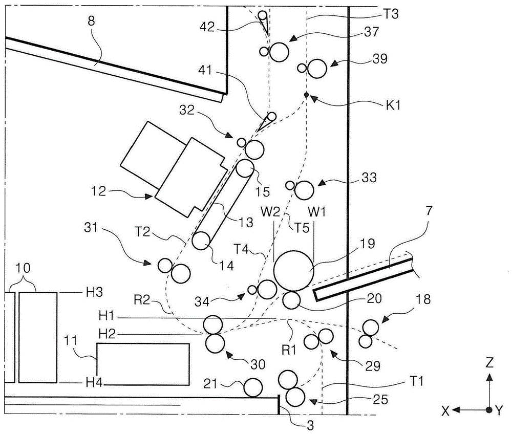
从输送辊对29起的下游的介质输送路径以向上凸起的方式弯曲,介质通过该弯曲路径部分后到达输送辊对30。以下,将从各介质盒送出的介质到达输送辊对30为止的介质输送路径称为“供给路径T1”。另外,将供给路径T1中位于输送辊对29与输送辊对30之间并以向上凸起的方式弯曲的路径部分称为“第一弯曲路径R1”。供给路径T1是使从各介质盒送出的介质朝向包含与从各介质盒送出介质的方向即-X方向相反的方向即+X方向的分量的输送方向翻转的路径。而且,该供给路径T1在输送辊对30的上游附近与后述翻转路径T4汇合。The medium conveying path downstream from the conveying
此外,位于输送辊对29附近且图示于装置主体2外侧的外部输送辊对18是设置于图1中省略图示的增设单元中的辊对。该增设单元构成为能够收纳介质,并构成为能够通过外部输送辊对18将从未图示的送出辊送出的介质供给至打印机1内。Moreover, the outer
另外,第一弯曲路径R1的附近设置有从装置主体2的侧面朝向装置外部突出的供给托盘7。供给托盘7是用于手动进给介质的托盘,介质从供给托盘7通过供给辊19和分离辊20而被供给至打印机1内。此外,经由供给托盘7送入装置内部的介质在进入供给路径T1之后,进入后述的翻转路径T4。In addition, a
接着,从输送辊对29受到输送力的介质通过以向下凸起的方式弯曲的弯曲路径到达输送辊对31。此外,以下将后述的在输送辊对34与输送辊对31之间以向下凸起的方式弯曲的弯曲路径称为“第二弯曲路径R2”。第二弯曲路径R2是构成后述的翻转路径T4的路径。Next, the medium receiving the conveying force from the conveying
从输送辊对31受到输送力的介质被输送至作为记录部和液体喷出头的一例的行式头12与输送带13之间、即与行式头12对置的记录位置。此外,以下将从输送辊对31至输送辊对32为止的介质输送路径称为“记录时输送路径T2”。The medium receiving the conveying force from the conveying
行式头12向介质的面喷出作为液体的一例的油墨而执行记录。The
行式头12是构成为喷出油墨的喷嘴将介质宽度方向的整个区域覆盖的喷墨头,并构成为不随着在介质宽度方向上移动而能够在整个介质宽度区域内进行记录的喷墨头。但是,喷墨头并不限于此,也可以是搭载于滑架并且一边在介质宽度方向上移动一边喷出油墨的类型。The
需要说明的是,附图标记10是收纳油墨的、作为液体收纳部的油墨收纳部。从行式头12喷出的油墨从油墨收纳部10经由省略图示的管而供给至行式头12。油墨收纳部10由沿X轴方向配置的多个油墨容器构成。It should be noted that
另外,附图标记11是储存从行式头12朝向未图示的冲洗盖喷出以进行维护的、作为废液的油墨的废液收纳部。In addition,
输送带13是挂绕在带轮14和带轮15上的环形带,并通过利用未图示的电机驱动带轮14和带轮15中的至少一方而进行旋转。介质一边被吸附在输送带13的带面上一边在与行式头12对置的位置上输送。相对于输送带13的介质的吸附,可以采用空气吸引方式、静电吸附方式等公知的吸附方式。The
在此,从与行式头12对置的位置通过的记录时输送路径T2呈相对于水平方向和铅垂方向形成角度,并朝上输送介质的构成。该朝上的输送方向在图1中是包含-X方向分量和+Z方向分量的方向,通过这样的构成,能够抑制打印机1的水平方向尺寸。Here, the recording conveyance path T2 passing through the position facing the
此外,在本实施方式中,记录时输送路径T2相对于水平方向被设定为50°~70°的范围的倾斜角,更为具体而言被设定为大致60°的倾斜角。In addition, in the present embodiment, the transport path T2 during recording is set at an inclination angle in the range of 50° to 70° with respect to the horizontal direction, more specifically, at an inclination angle of approximately 60°.
被行式头12在第一面上进行了记录的介质通过位于输送带13下游的输送辊对32进一步朝向包含-X方向分量和+Z方向分量的斜上方输送。The medium recorded on the first surface by the
在输送辊对32的下游设置有挡板41,通过该挡板41切换介质的输送方向。在原样直接排出介质的情况下,介质的输送路径被挡板41切换为朝向上方的输送辊对37。在输送辊对37的下游还设置有挡板42,通过该挡板42将输送路径切换为从排出位置A1排出和朝向位于铅垂方向更上方的输送辊对38输送中的任意一个。介质在朝向输送辊对38输送的情况下,从排出位置A2排出。A
从排出位置A1排出的介质由朝向包含+X方向分量和+Z方向分量的斜上方倾斜的排出托盘8接收。从排出位置A2排出的介质由未图示的可选托盘接收。The medium discharged from the discharge position A1 is received by the
当除了介质的第一面之外还在第二面上进行记录时,介质通过挡板41而被输往包含-X方向分量和+Z方向分量的斜上方,并通过分支位置K1进入转向路径T3。在本实施方式中,转向路径T3为从分支位置K1朝向上侧的介质输送路径。转向路径T3中设置有输送辊对39。进入转向路径T3的介质被输送辊对39朝向上方输送,然后,在介质的后端通过分支位置K1之后,切换输送辊对39的旋转方向,由此朝向下方输送介质。When recording is performed on the second side in addition to the first side of the medium, the medium is conveyed obliquely upward including the -X direction component and the +Z direction component through the
转向路径T3上连接有翻转路径T4。在本实施方式中,翻转路径T4是从分支位置K1起通过输送辊对33、34、30到达输送辊对31的介质输送路径。翻转路径T4中包含上述第二弯曲路径R2。A turning path T4 is connected to the turning path T3. In this embodiment, the reversing path T4 is a medium conveying path from the branch position K1 to the conveying
被输送辊对33朝向下方输送的介质从输送辊对33和输送辊对34受到输送力而到达输送辊对30,并被输送辊对30再次输送至与行式头12对置的位置。即,翻转路径T4是朝向包含铅垂下方的分量的输送方向输送介质,并经由向下凸起的第二弯曲路径R2使介质朝向包含铅垂上方的分量的输送方向翻转的路径。The medium conveyed downward by the conveying
在被再次输送至与行式头12对置的位置处的介质中,与已经进行了记录的第一面相反侧的第二面与行式头12对置。由此,行式头12能够对介质的第二面进行记录。在第二面进行了记录的介质从上述排出位置A1或排出位置A2排出。Of the medium conveyed again to the position facing the
以下,参照图2进一步对介质输送路径的构成进行说明。Hereinafter, the configuration of the medium transport path will be further described with reference to FIG. 2 .
在图2中,位置H1是铅垂方向上的第一弯曲路径R1的上端位置,位置H2是铅垂方向上的第二弯曲路径R2的下端位置。铅垂方向上的位置H1位于位置H2的上方。即,从沿着水平方向的方向即X轴方向来看,是第一弯曲路径R1的至少一部分与第二弯曲路径R2的至少一部分重叠的构成。换言之,是第一弯曲路径R1和第二弯曲路径R2在铅垂方向上重叠的构成。In FIG. 2 , position H1 is the upper end position of the first curved path R1 in the vertical direction, and position H2 is the lower end position of the second curved path R2 in the vertical direction. The position H1 in the vertical direction is located above the position H2. That is, at least a part of the first curved path R1 overlaps with at least a part of the second curved path R2 when viewed along the horizontal direction, that is, the X-axis direction. In other words, it is a configuration in which the first curved path R1 and the second curved path R2 overlap in the vertical direction.
因此,即使在为了确保翻转路径T4的路径长度而将第二弯曲路径R2配置于更下方的情况下,也能够抑制装置的高度方向尺寸。Therefore, even when the second curved path R2 is disposed further below in order to secure the path length of the inversion path T4, it is possible to suppress the dimension in the height direction of the device.
此外,在本实施方式中,从X轴方向来看,是第一弯曲路径R1的一部分与第二弯曲路径R2的一部分重叠的构成,但也可以是第一弯曲路径R1的全部与第二弯曲路径R2的一部分重叠的构成,或者还可以是第二弯曲路径R2的全部与第一弯曲路径R1的一部分重叠的构成。In addition, in this embodiment, a part of the first curved route R1 overlaps a part of the second curved route R2 when viewed from the X-axis direction, but the entire first curved route R1 may overlap with the second curved route R1. A part of the route R2 overlaps, or a configuration in which the entire second curved route R2 overlaps a part of the first curved route R1 may be used.
另外,在本实施方式中,第二弯曲路径R2的曲率小于第一弯曲路径R1的曲率。由此,与在第一弯曲路径R1使介质弯曲时、即使第一面和第二面均未进行记录的介质弯曲时相比,在第二弯曲路径R2使介质弯曲时能够平缓地弯曲。即,在使已进行了记录而刚性降低的介质弯曲时更平缓地弯曲,因此,不易在介质上形成褶皱等损伤,进而能够获得良好的记录结果。In addition, in the present embodiment, the curvature of the second curved path R2 is smaller than the curvature of the first curved path R1. As a result, when the medium is curved along the first curved path R1 , even if the medium is not recorded on either the first surface or the second surface, the medium can be curved more gently when the medium is curved along the second curved path R2 . That is, when a medium that has been recorded and its rigidity is reduced is bent more gently, damage such as wrinkles is less likely to be formed on the medium, and a good recording result can be obtained.
另外,在本实施方式中,在铅垂方向上行式头12与第一介质盒3之间具有油墨收纳部10。在图2中,位置H3是铅垂方向上的油墨收纳部10的上端位置,位置H4是铅垂方向上的油墨收纳部10的下端位置。在铅垂方向上,位置H1和位置H2位于位置H3与位置H4之间。即,从沿着水平方向的方向即X轴方向来看,是油墨收纳部10的至少一部分、第一弯曲路径R1的至少一部分以及第二弯曲路径R2的至少一部分重叠的构成。换言之,是油墨收纳部10的至少一部分、第一弯曲路径R1的至少一部分以及第二弯曲路径R2的至少一部分在铅垂方向上重叠的构成。通过这样的构成,能够抑制装置的高度方向尺寸。In addition, in this embodiment, the
另外,翻转路径T4中位于第二弯曲路径R2的上游且朝向包含铅垂下方的分量的输送方向输送介质的向下输送路径T5沿着从装置外表面朝向装置中心部的方向倾斜。向下输送路径T5是翻转路径T4的一部分,且是从输送辊对33的上游附近至输送辊对34为止的直线状的路径。In addition, the downward transport path T5 , which is located upstream of the second curved path R2 and transports the medium in the transport direction including the vertically downward component, is inclined in the direction from the outer surface of the device toward the center of the device. The downward conveyance path T5 is a part of the inversion path T4, and is a linear path from the upstream vicinity of the
该直线状的向下输送路径T5倾斜,因而成为在向下输送路径T5的下侧形成有空间的状态。并且,成为供给辊19进入该空间的状态。在图2中,位置W1是供给辊19的-X方向的端部位置,位置W2是供给辊19的+X方向的端部位置。从图2明确可知,从铅垂方向来看,向下输送路径T5的至少一部分与供给辊19的至少一部分重叠。换言之,向下输送路径T5的至少一部分与供给辊19的至少一部分在水平方向上重叠。通过这样的构成,能够抑制装置的水平方向尺寸。Since the linear downward conveyance path T5 is inclined, a space is formed below the downward conveyance path T5. Then, the
此外,在本实施方式中,从铅垂方向来看是向下输送路径T5的一部分与供给辊19的一部分重叠的构成,但也可以是向下输送路径T5全部与供给辊19的一部分重叠,还可以是供给辊19的全部与向下输送路径T5的一部分重叠。In addition, in this embodiment, a part of the downward conveyance path T5 overlaps with a part of the
本发明并不限定于上述所说明的实施方式,当然能够在权利要求书所记载的发明范围内实施各种变形,而且它们都包含在本发明的范围内。The present invention is not limited to the embodiments described above, and of course various modifications can be made within the scope of the invention described in the claims, and all of them are included in the scope of the present invention.
例如,在本实施方式中,记录时输送路径T2斜向上倾斜,但也可以沿着铅垂方向,还可以沿着水平方向。For example, in the present embodiment, the transport path T2 is inclined upward during recording, but it may also be along the vertical direction or the horizontal direction.
另外,在本实施方式中,向下输送路径T5斜向下倾斜,但是若不考虑与供给辊19在水平方向上重叠,则也可以沿着铅垂方向。In addition, in this embodiment, the downward conveyance path T5 inclines obliquely downward, but it may follow the vertical direction as long as overlapping with the
另外,也可以省略经由供给托盘7的介质的供给单元、通过外部输送辊对18从增设单元供给介质的供给单元。In addition, a supply unit for supplying the medium via the
另外,也可以构成为从供给托盘7通过供给辊19和分离辊20供给至打印机1内的介质如图3所示进入到翻转路径T4。通过这样构成,能够像图3中附图标记7A所示的供给托盘、附图标记19A所示的供给辊以及附图标记20A所示的分离辊那样将它们进一步设置在铅垂上方。即,能够提高供给托盘、供给辊以及分离辊的配置自由度。Alternatively, the medium supplied from the
Claims (20)
Priority Applications (2)
| Application Number | Priority Date | Filing Date | Title |
|---|---|---|---|
| CN202210932943.2A CN115195295B (en) | 2020-01-31 | 2021-01-28 | recording device |
| CN202210932944.7A CN115195296B (en) | 2020-01-31 | 2021-01-28 | recording device |
Applications Claiming Priority (2)
| Application Number | Priority Date | Filing Date | Title |
|---|---|---|---|
| JP2020014857A JP7427981B2 (en) | 2020-01-31 | 2020-01-31 | recording device |
| JP2020-014857 | 2020-01-31 |
Related Child Applications (2)
| Application Number | Title | Priority Date | Filing Date |
|---|---|---|---|
| CN202210932943.2A Division CN115195295B (en) | 2020-01-31 | 2021-01-28 | recording device |
| CN202210932944.7A Division CN115195296B (en) | 2020-01-31 | 2021-01-28 | recording device |
Publications (2)
| Publication Number | Publication Date |
|---|---|
| CN113276552A CN113276552A (en) | 2021-08-20 |
| CN113276552B true CN113276552B (en) | 2022-10-28 |
Family
ID=77061652
Family Applications (3)
| Application Number | Title | Priority Date | Filing Date |
|---|---|---|---|
| CN202210932944.7A Active CN115195296B (en) | 2020-01-31 | 2021-01-28 | recording device |
| CN202110121683.6A Active CN113276552B (en) | 2020-01-31 | 2021-01-28 | Recording apparatus |
| CN202210932943.2A Active CN115195295B (en) | 2020-01-31 | 2021-01-28 | recording device |
Family Applications Before (1)
| Application Number | Title | Priority Date | Filing Date |
|---|---|---|---|
| CN202210932944.7A Active CN115195296B (en) | 2020-01-31 | 2021-01-28 | recording device |
Family Applications After (1)
| Application Number | Title | Priority Date | Filing Date |
|---|---|---|---|
| CN202210932943.2A Active CN115195295B (en) | 2020-01-31 | 2021-01-28 | recording device |
Country Status (3)
| Country | Link |
|---|---|
| US (5) | US11413887B2 (en) |
| JP (3) | JP7427981B2 (en) |
| CN (3) | CN115195296B (en) |
Families Citing this family (2)
| Publication number | Priority date | Publication date | Assignee | Title |
|---|---|---|---|---|
| JP7427981B2 (en) * | 2020-01-31 | 2024-02-06 | セイコーエプソン株式会社 | recording device |
| JP7800084B2 (en) * | 2021-12-01 | 2026-01-16 | セイコーエプソン株式会社 | Recording device |
Family Cites Families (32)
| Publication number | Priority date | Publication date | Assignee | Title |
|---|---|---|---|---|
| JP2703960B2 (en) * | 1988-12-20 | 1998-01-26 | キヤノン株式会社 | Sheet feeding device |
| US5467182A (en) * | 1994-11-18 | 1995-11-14 | Xerox Corporation | Sheet transport for high productivity trayless duplex |
| JP2003073038A (en) * | 2001-08-31 | 2003-03-12 | Canon Inc | Image forming device |
| JP2004035132A (en) * | 2002-07-01 | 2004-02-05 | Ricoh Co Ltd | Image forming device |
| JP3748444B2 (en) | 2003-10-02 | 2006-02-22 | シャープ株式会社 | Composite paper feeding unit and image forming apparatus provided with the composite paper feeding unit |
| JP2005112605A (en) * | 2003-10-10 | 2005-04-28 | Murata Mach Ltd | Reverse transfer device |
| JP4323938B2 (en) * | 2003-12-10 | 2009-09-02 | キヤノン株式会社 | Image forming apparatus |
| US7506948B2 (en) * | 2004-08-18 | 2009-03-24 | Ricoh Company, Ltd. | Image formation apparatus |
| JP2007108657A (en) * | 2005-09-16 | 2007-04-26 | Ricoh Co Ltd | Image forming apparatus |
| JP2008072481A (en) * | 2006-09-14 | 2008-03-27 | Fuji Xerox Co Ltd | Image forming apparatus |
| JP5014838B2 (en) * | 2007-03-02 | 2012-08-29 | 株式会社リコー | Image forming apparatus |
| JP4999537B2 (en) * | 2007-05-10 | 2012-08-15 | キヤノン株式会社 | Recording device |
| JP2010228875A (en) | 2009-03-27 | 2010-10-14 | Brother Ind Ltd | Image recording device |
| JP2012076397A (en) * | 2010-10-04 | 2012-04-19 | Seiko Epson Corp | Recording device |
| JP2012196800A (en) * | 2011-03-18 | 2012-10-18 | Seiko Epson Corp | Waste liquid container and liquid consumption apparatus |
| JP6217898B2 (en) * | 2013-03-29 | 2017-10-25 | セイコーエプソン株式会社 | Recording device |
| US9254694B2 (en) * | 2014-03-27 | 2016-02-09 | Seiko Epson Corporation | Recording apparatus |
| JP6344121B2 (en) * | 2014-07-31 | 2018-06-20 | セイコーエプソン株式会社 | Recording device |
| JP6397268B2 (en) * | 2014-08-25 | 2018-09-26 | キヤノン株式会社 | Recording apparatus, control method therefor, program, and storage medium |
| JP2016124242A (en) | 2015-01-07 | 2016-07-11 | セイコーエプソン株式会社 | Recording device |
| JP6686285B2 (en) * | 2015-03-27 | 2020-04-22 | セイコーエプソン株式会社 | Recording system |
| JP6805677B2 (en) * | 2016-09-26 | 2020-12-23 | 富士ゼロックス株式会社 | Opening and closing mechanism and image forming device |
| US10241465B2 (en) * | 2016-09-26 | 2019-03-26 | Fuji Xerox Co., Ltd. | Opening and closing mechanism and image forming apparatus |
| CN107973153B (en) * | 2016-10-21 | 2021-05-04 | 佳能精技立志凯株式会社 | Medium conveyance device and image forming apparatus |
| JP7027747B2 (en) | 2017-01-18 | 2022-03-02 | セイコーエプソン株式会社 | Recording device |
| JP6736497B2 (en) | 2017-02-17 | 2020-08-05 | キヤノン株式会社 | Inkjet recording device |
| JP6957203B2 (en) * | 2017-05-29 | 2021-11-02 | キヤノン株式会社 | Sheet transfer device and image forming device |
| EP3424726B1 (en) | 2017-07-07 | 2021-09-22 | Canon Kabushiki Kaisha | Inkjet printing apparatus and control method of the inkjet printing apparatus |
| JP7103735B2 (en) * | 2018-04-11 | 2022-07-20 | 理想科学工業株式会社 | Image recorder |
| JP2019206091A (en) | 2018-05-28 | 2019-12-05 | セイコーエプソン株式会社 | Recording device |
| US11247859B2 (en) | 2018-06-27 | 2022-02-15 | Canon Kabushiki Kaisha | Image forming apparatus having controlled sheet feeding |
| JP7427981B2 (en) | 2020-01-31 | 2024-02-06 | セイコーエプソン株式会社 | recording device |
-
2020
- 2020-01-31 JP JP2020014857A patent/JP7427981B2/en active Active
-
2021
- 2021-01-28 CN CN202210932944.7A patent/CN115195296B/en active Active
- 2021-01-28 CN CN202110121683.6A patent/CN113276552B/en active Active
- 2021-01-28 CN CN202210932943.2A patent/CN115195295B/en active Active
- 2021-01-28 US US17/160,800 patent/US11413887B2/en active Active
-
2022
- 2022-02-22 US US17/651,986 patent/US11780245B2/en active Active
- 2022-07-27 US US17/815,496 patent/US11707936B2/en active Active
-
2023
- 2023-06-09 US US18/332,569 patent/US12138907B2/en active Active
-
2024
- 2024-01-22 JP JP2024007541A patent/JP7647950B2/en active Active
- 2024-10-11 US US18/913,573 patent/US20250033380A1/en active Pending
-
2025
- 2025-03-03 JP JP2025032888A patent/JP7782741B2/en active Active
Also Published As
| Publication number | Publication date |
|---|---|
| CN115195296A (en) | 2022-10-18 |
| JP7782741B2 (en) | 2025-12-09 |
| JP2024032824A (en) | 2024-03-12 |
| US20220363075A1 (en) | 2022-11-17 |
| US20210237481A1 (en) | 2021-08-05 |
| US20230331003A1 (en) | 2023-10-19 |
| JP2021121556A (en) | 2021-08-26 |
| US11780245B2 (en) | 2023-10-10 |
| US11707936B2 (en) | 2023-07-25 |
| US20250033380A1 (en) | 2025-01-30 |
| US20220169043A1 (en) | 2022-06-02 |
| JP7427981B2 (en) | 2024-02-06 |
| JP2025074244A (en) | 2025-05-13 |
| JP7647950B2 (en) | 2025-03-18 |
| CN115195295B (en) | 2023-12-26 |
| CN115195295A (en) | 2022-10-18 |
| CN115195296B (en) | 2023-12-26 |
| US12138907B2 (en) | 2024-11-12 |
| CN113276552A (en) | 2021-08-20 |
| US11413887B2 (en) | 2022-08-16 |
Similar Documents
| Publication | Publication Date | Title |
|---|---|---|
| JP7782741B2 (en) | Recording device | |
| JP7704256B2 (en) | Recording device | |
| CN114619763B (en) | Recording device | |
| CN116118368B (en) | Recording device | |
| JP2023073673A (en) | recording device | |
| CN115230327B (en) | Recording device | |
| JP7800084B2 (en) | Recording device | |
| CN114940022B (en) | recording device | |
| JP2022167139A (en) | recording device | |
| JP2022108820A (en) | Media transport device and recording device | |
| JP2021154581A (en) | Inkjet recording device | |
| JP2016088053A (en) | Recording device | |
| JP2022094292A (en) | Recording device |
Legal Events
| Date | Code | Title | Description |
|---|---|---|---|
| PB01 | Publication | ||
| PB01 | Publication | ||
| SE01 | Entry into force of request for substantive examination | ||
| SE01 | Entry into force of request for substantive examination | ||
| GR01 | Patent grant | ||
| GR01 | Patent grant |