CN113276210B - Vegetable slicing device capable of preventing sticking knife by utilizing air to push - Google Patents
Vegetable slicing device capable of preventing sticking knife by utilizing air to push Download PDFInfo
- Publication number
- CN113276210B CN113276210B CN202110628741.4A CN202110628741A CN113276210B CN 113276210 B CN113276210 B CN 113276210B CN 202110628741 A CN202110628741 A CN 202110628741A CN 113276210 B CN113276210 B CN 113276210B
- Authority
- CN
- China
- Prior art keywords
- mounting
- plate
- bevel gear
- spline
- frame
- Prior art date
- Legal status (The legal status is an assumption and is not a legal conclusion. Google has not performed a legal analysis and makes no representation as to the accuracy of the status listed.)
- Active
Links
Images


Classifications
-
- B—PERFORMING OPERATIONS; TRANSPORTING
- B26—HAND CUTTING TOOLS; CUTTING; SEVERING
- B26D—CUTTING; DETAILS COMMON TO MACHINES FOR PERFORATING, PUNCHING, CUTTING-OUT, STAMPING-OUT OR SEVERING
- B26D11/00—Combinations of several similar cutting apparatus
-
- B—PERFORMING OPERATIONS; TRANSPORTING
- B26—HAND CUTTING TOOLS; CUTTING; SEVERING
- B26D—CUTTING; DETAILS COMMON TO MACHINES FOR PERFORATING, PUNCHING, CUTTING-OUT, STAMPING-OUT OR SEVERING
- B26D1/00—Cutting through work characterised by the nature or movement of the cutting member or particular materials not otherwise provided for; Apparatus or machines therefor; Cutting members therefor
- B26D1/01—Cutting through work characterised by the nature or movement of the cutting member or particular materials not otherwise provided for; Apparatus or machines therefor; Cutting members therefor involving a cutting member which does not travel with the work
- B26D1/04—Cutting through work characterised by the nature or movement of the cutting member or particular materials not otherwise provided for; Apparatus or machines therefor; Cutting members therefor involving a cutting member which does not travel with the work having a linearly-movable cutting member
- B26D1/06—Cutting through work characterised by the nature or movement of the cutting member or particular materials not otherwise provided for; Apparatus or machines therefor; Cutting members therefor involving a cutting member which does not travel with the work having a linearly-movable cutting member wherein the cutting member reciprocates
- B26D1/08—Cutting through work characterised by the nature or movement of the cutting member or particular materials not otherwise provided for; Apparatus or machines therefor; Cutting members therefor involving a cutting member which does not travel with the work having a linearly-movable cutting member wherein the cutting member reciprocates of the guillotine type
-
- B—PERFORMING OPERATIONS; TRANSPORTING
- B26—HAND CUTTING TOOLS; CUTTING; SEVERING
- B26D—CUTTING; DETAILS COMMON TO MACHINES FOR PERFORATING, PUNCHING, CUTTING-OUT, STAMPING-OUT OR SEVERING
- B26D3/00—Cutting work characterised by the nature of the cut made; Apparatus therefor
- B26D3/28—Splitting layers from work; Mutually separating layers by cutting
-
- B—PERFORMING OPERATIONS; TRANSPORTING
- B26—HAND CUTTING TOOLS; CUTTING; SEVERING
- B26D—CUTTING; DETAILS COMMON TO MACHINES FOR PERFORATING, PUNCHING, CUTTING-OUT, STAMPING-OUT OR SEVERING
- B26D7/00—Details of apparatus for cutting, cutting-out, stamping-out, punching, perforating, or severing by means other than cutting
- B26D7/06—Arrangements for feeding or delivering work of other than sheet, web, or filamentary form
- B26D7/0608—Arrangements for feeding or delivering work of other than sheet, web, or filamentary form by pushers
-
- B—PERFORMING OPERATIONS; TRANSPORTING
- B26—HAND CUTTING TOOLS; CUTTING; SEVERING
- B26D—CUTTING; DETAILS COMMON TO MACHINES FOR PERFORATING, PUNCHING, CUTTING-OUT, STAMPING-OUT OR SEVERING
- B26D7/00—Details of apparatus for cutting, cutting-out, stamping-out, punching, perforating, or severing by means other than cutting
- B26D7/18—Means for removing cut-out material or waste
- B26D7/1818—Means for removing cut-out material or waste by pushing out
-
- B—PERFORMING OPERATIONS; TRANSPORTING
- B26—HAND CUTTING TOOLS; CUTTING; SEVERING
- B26D—CUTTING; DETAILS COMMON TO MACHINES FOR PERFORATING, PUNCHING, CUTTING-OUT, STAMPING-OUT OR SEVERING
- B26D7/00—Details of apparatus for cutting, cutting-out, stamping-out, punching, perforating, or severing by means other than cutting
- B26D7/26—Means for mounting or adjusting the cutting member; Means for adjusting the stroke of the cutting member
- B26D7/2628—Means for adjusting the position of the cutting member
-
- B—PERFORMING OPERATIONS; TRANSPORTING
- B26—HAND CUTTING TOOLS; CUTTING; SEVERING
- B26D—CUTTING; DETAILS COMMON TO MACHINES FOR PERFORATING, PUNCHING, CUTTING-OUT, STAMPING-OUT OR SEVERING
- B26D11/00—Combinations of several similar cutting apparatus
- B26D2011/005—Combinations of several similar cutting apparatus in combination with different kind of cutters, e.g. two serial slitters in combination with a transversal cutter
-
- B—PERFORMING OPERATIONS; TRANSPORTING
- B26—HAND CUTTING TOOLS; CUTTING; SEVERING
- B26D—CUTTING; DETAILS COMMON TO MACHINES FOR PERFORATING, PUNCHING, CUTTING-OUT, STAMPING-OUT OR SEVERING
- B26D2210/00—Machines or methods used for cutting special materials
- B26D2210/02—Machines or methods used for cutting special materials for cutting food products, e.g. food slicers
Abstract
The invention relates to a vegetable slicing device, in particular to a vegetable slicing device which is pushed by air to prevent a knife from sticking. The invention aims to provide a vegetable slicing device capable of avoiding sticking a knife and rapidly slicing and preventing sticking the knife by utilizing air pushing. The technical embodiment of the invention relates to a vegetable slicing device capable of preventing a knife from sticking by utilizing air to push, which comprises a mounting frame, a containing plate, a blanking plate, a guard plate and a vegetable slicing mechanism, wherein the containing plate is arranged on the inner side wall of the mounting frame, the blanking plate is arranged on one side, close to the containing plate, of the inner side wall of the mounting frame, the guard plates are arranged on two sides of the mounting frame, and the vegetable slicing mechanism is arranged in the mounting frame. The vegetable slicing machine provided by the invention is matched with the power mechanism, and simultaneously pushes the vegetables forwards, so that slicing of the vegetables can be completed, the vegetable slicing mechanism can avoid sticking a cutter to the sliced vegetables, and simultaneously, the sliced vegetables can be pushed forwards to the blanking plate, so that the sliced vegetables can slide down and be collected conveniently.
Description
Technical Field
The invention relates to a vegetable slicing device, in particular to a vegetable slicing device which is pushed by air to prevent a knife from sticking.
Background
Food processing refers to cereal milling, feed processing, vegetable oil and sugar processing, slaughtering, meat processing, aquatic product processing, and processing activities of foods such as vegetables, fruits and nuts, and processing of potatoes, dehydrated vegetables and canned vegetables, which are directly carried out by taking agricultural, forestry, pasturing and fishery products as raw materials, and is one type of broad agricultural product processing industry.
In the prior art, when slicing vegetables, the vegetables are usually put into the existing slicing equipment, then the existing slicing equipment is operated to slice the vegetables, and when slicing the vegetables, the sliced vegetables are easy to adhere to the side face of a cutter of the existing slicing equipment, so that the vegetables need to be manually removed, hands are easily scratched, in addition, when slicing the vegetables, the existing slicing equipment slices the vegetables downwards by utilizing a cutting edge, when the cutting edge is not sharp enough, the vegetables are easy to be extruded by the cutting edge, so that the vegetables deform to generate cracks, and inconvenience is caused to subsequent use.
Therefore, it is necessary to develop a vegetable slicing device capable of preventing sticking of a knife and rapidly slicing by using air to push the knife.
Disclosure of Invention
In order to overcome the defects that when the existing slicing equipment is used for slicing vegetables, the sliced vegetables are easy to adhere to a cutter and scratch when manually taken down, when the cutting edge is not sharp enough, the cutting edge is easy to squeeze the vegetables, so that the vegetables deform to generate cracks, and inconvenience is caused to subsequent use, the invention has the following technical problems: the vegetable slicing device can avoid sticking the knife and can quickly slice the vegetables by pushing the vegetables by air.
The technical implementation scheme of the invention is as follows: the utility model provides an utilize air to promote to prevent to glue vegetables section device of sword, including the mounting bracket, hold the board, flitch, backplate, vegetables section mechanism and power unit, the inside wall of mounting bracket is installed and is held the board, and the inside wall of mounting bracket is close to holding board one side and is provided with the flitch, and the both sides of mounting bracket all are provided with the backplate, are provided with vegetables section mechanism in the mounting bracket, are provided with power unit in the mounting bracket in the vegetables section mechanism outside, hold the board and install power unit, power unit and vegetables section mechanism rigid coupling.
In a preferred embodiment of the invention, the vegetable slicing mechanism comprises a threaded block, a threaded rod, a rotating plate, a connecting plate, a first mounting plate, a first spline rod, a first bevel gear, a first wedge gear, an L-shaped plate, a first rotating shaft, a second bevel gear, a sliding frame, a second spline rod, a third bevel gear and a cutting component, wherein the threaded block is connected to the top of the mounting frame, the threaded rod is arranged in the threaded block, the rotating plate is mounted at the upper end of the threaded rod, the lower end of the threaded rod penetrates through the mounting frame, the connecting plate is rotatably arranged at the lower end of the threaded rod, the first mounting plate is connected to two sides of the bottom of the connecting plate, the first bevel gear is mounted at the upper parts of the two first mounting plates through spline sleeves, the first wedge gear is arranged at the middle part of the first spline rod, the L-shaped plate is fixedly connected to the side wall of the connecting plate, the first rotating shaft is mounted at the lower part of the L-shaped plate, the second bevel gear is mounted at the first rotating shaft, a moving groove is formed in one side of the top of the mounting frame, the sliding groove is formed in the sliding frame, the lower part of the sliding frame is provided with the second spline shaft is arranged at the second spline shaft and is meshed with the first spline shaft and the second spline shaft is arranged at the second spline shaft and is far away from the first spline shaft.
In a preferred embodiment of the invention, the cutting component comprises a disc, a first connecting block, a second mounting plate, a vertical cutter, cutting teeth and a connecting frame, wherein the disc is connected to one side of the first rotating shaft far away from the L-shaped plate, the first connecting block is embedded in the eccentric position of the disc, the first connecting block is provided with the second mounting plate, the lower part of the second mounting plate is fixedly connected with the vertical cutter, the connecting frame is fixed on the inner side wall of the mounting frame at the lower side of the disc, a sliding groove is formed in the middle of the top of the connecting frame, and the vertical cutter is arranged in the sliding groove in a sliding mode.
In a preferred embodiment of the present invention, a plurality of grooves for pushing vegetables are formed on one side surface of the vertical cutter.
In a preferred embodiment of the present invention, the lower portion of the vertical cutter is beveled serrated.
In a preferred embodiment of the invention, the power mechanism comprises a third spline rod, a fixed plate, a fourth bevel gear, a fifth bevel gear, a mounting seat, a gear motor and a sixth bevel gear, wherein the third spline rod is provided with two third spline rods which are respectively connected to two sides of the mounting frame in a rotating way, the fixed plate is arranged between the upper parts of the two third spline rods through a spline housing, the third spline rod on the upper side of the fixed plate is provided with the fourth bevel gear, the two fourth bevel gears are respectively meshed with the two first bevel gears, the lower part of the third spline rod on one side is provided with the fifth bevel gear, one side, close to the fifth bevel gear, in the mounting frame is provided with the mounting seat, the top of the mounting seat is provided with the gear motor, the output shaft of the gear motor is provided with the sixth bevel gear, and the sixth bevel gear is meshed with the fifth bevel gear.
In a preferred embodiment of the invention, the device further comprises guide rods, a mounting frame, first springs, a second rotating shaft, a conveying roller, a first belt wheel and a power component, wherein two guide rods are arranged on two sides of the mounting frame in a sliding mode, the guide rods are located on the upper side of the containing plate, the mounting frame is fixedly connected between the two adjacent guide rods, the two first springs are fixedly connected between the mounting frame and the mounting frame, the four first springs are respectively wound on the outer sides of the four guide rods, the second rotating shaft is connected in the mounting frame in a rotating mode, the conveying roller is arranged on the second rotating shaft in the mounting frame, the lower end of the second rotating shaft penetrates through the containing plate, the first belt wheel is connected with the lower end of the second rotating shaft on one side, the power component is fixedly connected with the third spline rod, and the power component is matched with the first belt wheel.
In a preferred embodiment of the invention, the power component comprises a first hollow frame, a second hollow frame, sliding blocks, a second spring, a third rotating shaft, a second belt pulley, a third belt pulley and a belt, wherein the first hollow frame is arranged on one side, close to the gear motor, of the mounting frame, the second hollow frame is arranged on one side, close to the first hollow frame, of the mounting frame, sliding blocks are arranged in the first hollow frame and the second hollow frame in a sliding mode, the second spring is fixedly connected between two adjacent sliding blocks and the first hollow frame, the second spring is also connected between two adjacent sliding blocks and the second hollow frame, the third rotating shaft is rotatably arranged in the middle of the sliding blocks, the second belt pulley is arranged at the lower part of the third rotating shaft, the third spline bar on the lower side of the fifth bevel gear is provided with the third belt pulley, and the belt is wound between the first belt pulley, the third belt pulley and the two second belt pulleys.
In a preferred embodiment of the invention, the device further comprises a second connecting block, a screw rod, a fixed block, a transverse cutter and a vertical plate, wherein the second connecting block is fixedly connected to one side, far away from the mounting seat, of the mounting frame, the screw rod is arranged in the second connecting block in a threaded mode, the fixed block is connected to the lower end of the screw rod, a chute is arranged on the mounting frame at the lower side of the second connecting block, the lateral wall of the fixed block is connected with the transverse cutter, the transverse cutter penetrates through the chute, the vertical plate is fixedly connected to the inner side wall of the mounting frame at the upper side of the containing plate, and the transverse cutter and the vertical plate are arranged in a sliding mode.
Compared with the prior art, the invention has the following advantages:
1. the vegetable slicing machine is matched with the power mechanism, and simultaneously pushes the vegetables forwards, so that slicing of the vegetables can be completed, the vegetable slicing mechanism can avoid sticking a cutter to the sliced vegetables, and meanwhile, the sliced vegetables can be pushed forwards to the blanking plate, so that the sliced vegetables can slide and be collected conveniently;
2. the left conveying roller rotates clockwise and the right conveying roller is matched with the left conveying roller to convey vegetables forwards, so that the vegetables do not need to be pushed forwards, and the labor intensity can be reduced;
3. the screw rod rotates clockwise or anticlockwise to enable the height of the transverse cutter to be adjusted, vegetables are pushed forwards to be matched with the transverse cutter, the vegetables can be transversely divided, and therefore the vegetables after slicing can be prevented from being too large, and inconvenience is caused to subsequent use.
Drawings
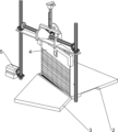
Fig. 1 is a schematic perspective view of the present invention.
Fig. 2 is a schematic perspective view of the mounting frame of the present invention.
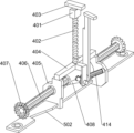
Fig. 3 is a schematic perspective view of a vegetable slicing mechanism according to the present invention.
Fig. 4 is a schematic view showing a partial perspective structure of the vegetable slicing mechanism of the present invention.
Fig. 5 is a schematic perspective view of a carriage according to the present invention.
Fig. 6 is a schematic perspective view of a vertical cutter according to the present invention.
Fig. 7 is a schematic perspective view of a connecting frame according to the present invention.
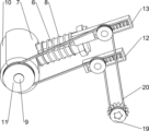
Fig. 8 is a schematic perspective view of the power mechanism of the present invention.
Fig. 9 is a schematic perspective view of a conveying roller according to the present invention.
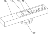
Fig. 10 is a schematic perspective view of a second hollow frame according to the present invention.
Fig. 11 is a schematic perspective view of a transverse cutter according to the present invention.
Wherein the above figures include the following reference numerals: 1. mounting rack, 2, holding plate, 3, blanking plate, 31, guard plate, 4, vegetable slicing mechanism, 401, screw block, 402, threaded rod, 403, swivel plate, 404, connecting plate, 405, first mounting plate, 406, first spline bar, 407, first bevel gear, 408, first wedge gear, 409, L-shaped plate, 410, first rotation shaft, 411, second bevel gear, 412, moving groove, 413, carriage, 414, second spline bar, 415, second wedge gear, 416, third bevel gear, 417, disc, 418, first connecting block, 419, second mounting plate, 420, vertical cutter, 421, connecting frame, 422, sliding groove, 5, a power mechanism, 501, a third spline rod, 502, a fixed plate, 503, a fourth bevel gear, 504, a fifth bevel gear, 505, a mounting seat, 506, a gear motor, 507, a sixth bevel gear, 6, a guide rod, 7, a mounting frame, 8, a first spring, 9, a second rotating shaft, 10, a conveying roller, 11, a first pulley, 12, a first hollow frame, 13, a second hollow frame, 14, a sliding block, 15, a second spring, 16, a third rotating shaft, 17, a second pulley, 19, a third pulley, 20, a belt, 21, a second connecting block, 22, a screw, 23, a fixed block, 24, a chute, 25, a transverse cutter, 26 and a vertical plate.
Detailed Description
It should be noted that in the various embodiments described, identical components are provided with identical reference numerals or identical component names, wherein the disclosure contained throughout the description can be transferred in a meaning to identical components having identical reference numerals or identical component names. The position specification, the upper, lower, lateral, etc. selected in the description are also referred to directly in the description and the figures shown and are transferred in the sense of a new position when the position is changed.
Example 1
The utility model provides an utilize air to promote to prevent to glue vegetables section device of sword, as shown in fig. 1-3, including mounting bracket 1, hold board 2, flitch 3, backplate 31, vegetables section mechanism 4 and power unit 5, the inside wall lower part of mounting bracket 1 is installed and is held board 2, hold the inside wall flitch 3 of mounting bracket 1 of board 2 front side, the left and right sides in mounting bracket 1 all is provided with backplate 31, be provided with vegetables section mechanism 4 in the mounting bracket 1 between two backplate 31 about, install power unit 5 in the mounting bracket 1 in the vegetables section mechanism 4 outside, power unit 5 and vegetables section mechanism 4 rigid coupling.
When the vegetables need to be sliced, the user adjusts vegetable slicing mechanism 4 according to the vegetables that need slice, so can slice different vegetables, then the user places vegetables on holding plate 2, and promote forward to suitable position, and make vegetables be located vegetable slicing mechanism 4's downside, then the user makes power unit 5 work, power unit 5 work can make vegetable slicing mechanism 4 construct work, vegetable slicing mechanism 4 constructs work and can slice vegetables, vegetable slicing mechanism 4 can promote forward the vegetables after slicing simultaneously, and need not manually take off the vegetables piece, so can avoid the hand fish tail, because the upper surface of flitch 3 is the inclined setting, the vegetables after the section is followed forward below landing, simultaneously the user collects the vegetables of downward landing, after the whole section of vegetables is accomplished, the user closes power unit 5, vegetable slicing mechanism 4 stops work thereupon, when needs to slice vegetables again, the user repeats the operation can.
Example 2
On the basis of the embodiment 1, as shown in fig. 4-7, the vegetable slicing mechanism 4 comprises a threaded block 401, a threaded rod 402, a rotating plate 403, a connecting plate 404, a first mounting plate 405, a first spline rod 406, a first bevel gear 407, a first wedge gear 408, an L-shaped plate 409, a first rotating shaft 410, a second bevel gear 411, a sliding frame 413, a second spline rod 414, a third bevel gear 416 and a cutting part, wherein the threaded block 401 is connected to the top of the mounting frame 1, the threaded rod 402 is arranged in the threaded block 401 in a threaded connection manner, the rotating plate 403 is mounted at the upper end of the threaded rod 402, the lower end of the threaded rod 402 penetrates through the mounting frame 1, the connecting plate 404 is rotatably arranged at the lower end of the threaded rod 402, the first mounting plates 405 are connected to the left side and the right side of the bottom of the connecting plate 404, the first spline rods 406 are mounted on the upper parts of the left and right first mounting plates 405 through spline sleeves, the first bevel gears 407 are mounted on the left and right sides of the first spline rod 406, the first spline rod 406 between the left and right first mounting plates 405 is provided with a first wedge gear 408, the rear side wall of the connecting plate 404 is fixedly connected with an L-shaped plate 409, the lower part of the L-shaped plate 409 is rotatably provided with a first rotating shaft 410, the front part of the first rotating shaft 410 is provided with a second bevel gear 411, the top of the mounting frame 1 at the left side of the threaded block 401 is provided with a moving groove 412, the moving groove 412 is slidably provided with a sliding frame 413, the lower part of the sliding frame 413 is provided with a second spline rod 414 through a spline sleeve, the left end of the second spline rod 414 is rotatably connected with the right side wall of the left first mounting plate 405, the right part of the second spline rod 414 is provided with a second wedge gear 415, the second wedge gear 415 is meshed with the first wedge gear 408, the second spline rod 414 at the right side of the second wedge gear 415 is provided with a third bevel gear 416, the third bevel gear 411 is meshed with the second bevel gear 411, the rear end of the first rotary shaft 410 is provided with a cutting member.
When the vegetables need to be sliced, the user rotates the threaded rod 402 clockwise or anticlockwise through the rotating plate 403, the threaded rod 402 can be moved upwards or downwards through the cooperation of the threaded block 401, the first rotating shaft 410 can be moved upwards or downwards through the connecting plate 404 and the L-shaped plate 409, the first rotating shaft 410 can be moved upwards or downwards to enable the cutting part to move, after the cutting part moves to a proper position, the user stops rotating the threaded rod 402, then the user enables the power mechanism 5 to work, the power mechanism 5 works to enable the left first bevel gear 407 to rotate anticlockwise, the left first bevel gear 407 rotates anticlockwise to enable the first spline rod 406 to rotate anticlockwise, the first spline rod 406 rotates anticlockwise to enable the first wedge gear 408 to rotate anticlockwise, the first bevel gear 407 enables the cutting part to work, the user pushes the vegetables to move forwards when the cutting part works, and after the vegetables are completely sliced, the user can turn off the power mechanism 5.
As shown in fig. 6 and 7, the cutting unit includes a disc 417, a first connecting block 418, a second mounting plate 419, a vertical cutter 420, cutting teeth and a connecting frame 421, wherein the disc 417 is connected to the rear end of the first rotating shaft 410, the first connecting block 418 is embedded in the eccentric position of the disc 417, the first connecting block 418 is provided with the second mounting plate 419, the vertical cutter 420 is fixedly connected to the lower portion of the second mounting plate 419, the connecting frame 421 is fixed to the inner side wall of the mounting frame 1 at the lower side of the disc 417, a sliding groove 422 is opened in the middle of the top of the connecting frame 421, and the vertical cutter 420 is slidably disposed in the sliding groove 422.
When it is desired to slice vegetables, the user repeats the above operation, so that the first rotation shaft 410 moves upward or downward, the disc 417 moves upward or downward, the vertical cutter 420 moves upward or downward through the first connection block 418 and the second mounting plate 419, the vertical cutter 420 moves upward or downward to a proper position, the user stops rotating the threaded rod 402, the vertical cutter 420 moves upward or downward through the sliding groove 422, the user moves the sliding frame 413 rightward or leftward, the sliding frame 413 moves rightward or leftward, the second wedge gear 415 moves rightward or leftward, and since the second wedge gear 415 is disposed in parallel with the first wedge gear 408, the second wedge gear 415 is always engaged with the first wedge gear 408, the second wedge gear 415 moves right or left to adjust the upward or downward moving speed of the vertical cutter 420, when the second wedge gear 415 moves right or left to a proper position, the user stops moving the carriage 413, then the user repeats the above operation to rotate the first wedge gear 408 counterclockwise, the second wedge gear 415 rotates clockwise, the second bevel gear 415 rotates clockwise to rotate the third bevel gear 416 clockwise through the second spline rod 414, the second bevel gear 411 rotates counterclockwise to rotate the disk 417 counterclockwise through the first rotating shaft 410, the vertical cutter 420 moves upward or downward through the cooperation of the first connecting block 418 and the second mounting plate 419, the user pushes the vegetables forward at the same time, the vertical cutter 420 moves upward or downward to slice the vegetables, since the front side of the vertical cutter 420 is opened with a plurality of grooves, when the vertical cutter 420 moves downwards to slice vegetables, air in the groove can push the sliced vegetables forwards, so that the sliced vegetables can be prevented from being stuck on the vertical cutter 420, the sliced vegetables do not need to be manually moved down from the vertical cutter 420, and further, the hand scratch of the vertical cutter 420 can be avoided, when the vertical cutter 420 moves downwards to slice the vegetables, the cutting edge of the vertical cutter 420 can be prevented from being sharp enough, when the vegetables are sliced, the vegetables are extruded to deform to cause cracks, the vegetable slicing is prevented, and after the vegetable slicing is completed, a user can close the power mechanism 5.
As shown in fig. 8, the power mechanism 5 includes a third spline rod 501, a fixed plate 502, a fourth bevel gear 503, a fifth bevel gear 504, a mounting seat 505, a gear motor 506 and a sixth bevel gear 507, the third spline rod 501 is provided with two, the two third spline rods 501 are respectively connected on the left side and the right side of the mounting frame 1 in a rotating manner, the fixed plate 502 is arranged between the upper parts of the left and the right third spline rods 501 through spline sleeves, the third spline rod 501 on the upper side of the fixed plate 502 is provided with the fourth bevel gear 503, the two fourth bevel gears 503 are respectively meshed with the two first bevel gears 407, the lower part of the left third spline rod 501 is provided with the fifth bevel gear 504, the mounting frame 1 on the left side of the fifth bevel gear 504 is provided with the mounting seat 505, the top of the mounting seat 505 is provided with the gear motor 506, the sixth bevel gear 507 is installed on the output shaft of the gear motor 506, and the sixth bevel gear 507 is meshed with the fifth bevel gear 504.
When the vegetable needs to be sliced, the user repeats the above operation to adjust the vertical cutter 420, then the user starts the gear motor 506 to rotate the sixth bevel gear 507 counterclockwise, the fifth bevel gear 504 rotates clockwise to rotate the left third spline 501, the left third spline 501 rotates clockwise to rotate the left fourth bevel gear 503 clockwise, the left fourth bevel gear 503 rotates clockwise to rotate the left first bevel gear 407 counterclockwise, so that the vertical cutter 420 moves upward or downward to power the vegetable slice, and after the vegetable is sliced completely, the user turns off the gear motor 506.
Example 3
On the basis of embodiment 2, as shown in fig. 9 and 10, still include guide arm 6, installing frame 7, first spring 8, second pivot 9, conveying roller 10, first band pulley 11 and power part, the left and right sides of mounting bracket 1 is all slidingtype is equipped with two guide arms 6, guide arm 6 is located the upside that holds board 2, the rigid coupling has installing frame 7 between upper and lower two adjacent guide arms 6, the rigid coupling has two first springs 8 between installing frame 7 and mounting bracket 1, wind respectively in the outside of four guide arms 6 between four first springs 8, be connected with second pivot 9 in the installing frame 7 rotation, second pivot 9 in the installing frame 7 is provided with conveying roller 10, the lower extreme of second pivot 9 passes and holds board 2, the lower extreme of left side second pivot 9 is connected with first band pulley 11, mounting bracket 1 is provided with power part, power part and third spline pole 501 rigid coupling, power part and first band pulley 11 cooperation.
When the vegetable is to be sliced, the user repeats the above operation, and the third spline lever 501 on the left side is rotated clockwise, the third spline lever 501 on the left side is rotated clockwise to operate the power member, the power member operates to rotate the first pulley 11 clockwise, the second rotary shaft 9 on the left side is rotated clockwise by the first pulley 11 clockwise to rotate the second rotary shaft 9 on the left side, the conveying roller 10 on the left side is rotated clockwise by the second rotary shaft 9 on the left side, the conveying roller 10 on the left side is rotated clockwise to convey the vegetable forward by the cooperation of the conveying roller 10 on the right side, and the conveying roller 10 on the left and right sides is always in contact with the vegetable by the first spring 8, so that the vegetable can be conveyed forward conveniently.
As shown in fig. 9 and 10, the power component includes a first hollow frame 12, a second hollow frame 13, a sliding block 14, a second spring 15, a third rotating shaft 16, a second belt pulley 17, a third belt pulley 19 and a belt 20, wherein the first hollow frame 12 is disposed at the left part in the mounting frame 1, the first hollow frame 12 is located at the upper side of the gear motor 506, the second hollow frame 13 is disposed in the mounting frame 1 at the rear side of the first hollow frame 12, the sliding blocks 14 are all slidably disposed in the first hollow frame 12 and the second hollow frame 13, the second spring 15 is fixedly connected between two adjacent sliding blocks 14 and the first hollow frame 12, the second spring 15 is also connected between two adjacent sliding blocks 14 and the second hollow frame 13, the third rotating shaft 16 is rotatably mounted at the middle part of the sliding block 14, the second belt pulley 17 is mounted at the lower part of the third rotating shaft 16, the third spline 501 at the lower side of the fifth bevel gear 504 is mounted at the third belt pulley 19, and the second belt pulley 20 is wound around the second belt pulley 17 between the first belt pulley 11 and the second belt pulley 19 and the second belt pulley 17.
When it is necessary to slice vegetables, the user repeats the above operation, and rotates the left third spline 501 clockwise, and rotates the third pulley 19 clockwise, and rotates the first pulley 11 clockwise through the belt 20, and rotates the first pulley 11 clockwise, and rotates the left second rotating shaft 9 clockwise, and rotates the left conveying roller 10 clockwise, so that vegetables are output forward, and the second pulley 17 and the third pulley 19 always contact the belt 20 through the cooperation of the second spring 15 and the slider 14, so that the belt 20 is prevented from loosening, and inconvenience is caused to the forward output of vegetables.
As shown in fig. 11, the device further comprises a second connecting block 21, a screw 22, a fixing block 23, a transverse cutter 25 and a vertical plate 26, wherein the second connecting block 21 is fixedly connected to the right part in the mounting frame 1, the screw 22 is arranged in the second connecting block 21 in a threaded manner, the lower end of the screw 22 is connected with the fixing block 23, the mounting frame 1 at the lower side of the second connecting block 21 is provided with a chute 24, the left side wall of the fixing block 23 is connected with the transverse cutter 25, the transverse cutter 25 penetrates through the chute 24, the vertical plate 26 is fixedly connected to the inner side wall of the mounting frame 1 at the upper side of the holding plate 2, and the transverse cutter 25 and the vertical plate 26 are arranged in a sliding manner.
Before the vegetables need to be sliced, the user adjusts the height of the transverse cutters 25 according to the size of the vegetables to be sliced, when the height of the transverse cutters 25 needs to be adjusted, the user rotates the screw 22 clockwise or anticlockwise, the screw 22 moves downwards or upwards along with the screw 22, the screw 22 moves downwards or upwards to enable the transverse cutters 25 to move upwards or downwards through the fixing blocks 23, the vertical plates 26 can guide the upwards or downwards movement of the transverse cutters 25, after the transverse cutters 25 move upwards or downwards to a proper position, the user stops rotating the screw 22, then the user repeats the operation, so that the vegetables push forwards, the vegetables push forwards through the transverse cutters 25, the vegetables can be transversely segmented, and inconvenience caused by subsequent use can be avoided.
While the disclosure has been described with respect to only a limited number of embodiments, those skilled in the art, having benefit of this disclosure, will appreciate that various other embodiments can be devised which do not depart from the scope of the invention as disclosed herein. Accordingly, the scope of the invention should be limited only by the attached claims.
Claims (2)
1. The utility model provides an utilize air to promote to prevent to glue vegetables section device of sword, including mounting bracket (1), hold board (2), flitch (3) and backplate (31), hold board (2) are installed to the inside wall of mounting bracket (1), the inside wall of mounting bracket (1) is close to holding board (2) one side and is provided with flitch (3), both sides of mounting bracket (1) all are provided with backplate (31), characterized by still including vegetables section mechanism (4) and power unit (5), be provided with vegetables section mechanism (4) in mounting bracket (1), be provided with power unit (5) in mounting bracket (1) in the outside of vegetables section mechanism (4), power unit (5) and vegetables section mechanism (4) rigid coupling;
vegetable slicing mechanism (4) including screw thread piece (401), threaded rod (402), rotating plate (403), connecting plate (404), first mounting panel (405), first spline pole (406), first bevel gear (407), first wedge gear (408), L shaped plate (409), first pivot (410), second bevel gear (411), carriage (413), second spline pole (414), third bevel gear (416) and cutting member, threaded piece (401) are connected at the top of mounting bracket (1), be equipped with threaded rod (402) in threaded piece (401), rotating plate (403) are installed to the upper end of threaded rod (402), the lower extreme of threaded rod (402) passes mounting bracket (1), the lower extreme rotation of connecting plate (402) is provided with connecting plate (404), the both sides of connecting plate (404) bottom all are connected with first mounting panel (405), first spline pole (406) are installed through the spline sleeve in the upper portion of two first mounting panels (405), first bevel gear (407) are all installed to the both sides of first spline pole (406), the middle part of first spline pole (406) is provided with rotating plate (408), the side wall (409) of first spline pole (408) is installed to the lower end rotation of threaded rod (402), the first rotating shaft (410) is provided with a second bevel gear (411), one side, close to the threaded block (401), of the top of the mounting frame (1) is provided with a moving groove (412), a sliding frame (413) is arranged in the moving groove (412) in a sliding mode, the lower part of the sliding frame (413) is provided with a second spline rod (414), the second spline rod (414) is rotatably connected with a first mounting plate (405) on one side, the second spline rod (414) is provided with a second wedge gear (415) through a spline sleeve, one side, close to the second wedge gear (415), of the second spline rod (414) is provided with a third bevel gear (416), the third bevel gear (416) is meshed with the second bevel gear (411), and one side, far away from the L-shaped plate (409), of the first rotating shaft (410) is provided with a cutting part;
the cutting component comprises a disc (417), a first connecting block (418), a second mounting plate (419), a vertical cutter (420), cutting teeth and a connecting frame (421), wherein the disc (417) is connected to one side, far away from the L-shaped plate (409), of the first rotating shaft (410), the first connecting block (418) is embedded in the eccentric position of the disc (417), the second mounting plate (419) is arranged on the first connecting block (418), the vertical cutter (420) is fixedly connected to the lower portion of the second mounting plate (419), the connecting frame (421) is fixed to the inner side wall of the mounting frame (1) at the lower side of the disc (417), a sliding groove (422) is formed in the middle of the top of the connecting frame (421), and the vertical cutter (420) is arranged in the sliding groove (422) in a sliding mode; the power mechanism (5) comprises a third spline rod (501), a fixed plate (502), a fourth bevel gear (503), a fifth bevel gear (504), a mounting seat (505), a gear motor (506) and a sixth bevel gear (507), wherein the third spline rod (501) is provided with two, the two third spline rods (501) are respectively connected to two sides of the mounting frame (1) in a rotating mode, the fixed plate (502) is arranged between the upper parts of the two third spline rods (501) through a spline sleeve, the third spline rod (501) on the upper side of the fixed plate (502) is provided with the fourth bevel gear (503), the two fourth bevel gears (503) are respectively meshed with the two first bevel gears (407), the lower part of the third spline rod (501) on one side is provided with the fifth bevel gear (504), one side, close to the fifth bevel gear (504), of the mounting frame (1) is provided with the mounting seat (505), the top of the mounting seat (505) is provided with the gear motor (506), the sixth bevel gear (507) is arranged on the output shaft of the gear motor (506), and the sixth bevel gear (507) is meshed with the fifth bevel gear (407); the automatic transmission device is characterized by further comprising guide rods (6), mounting frames (7), first springs (8), second rotating shafts (9), conveying rollers (10), first belt wheels (11) and power components, wherein two guide rods (6) are arranged on two sides of the mounting frame (1) in a sliding mode, the guide rods (6) are located on the upper side of the containing plate (2), the mounting frames (7) are fixedly connected between the two adjacent guide rods (6), the two first springs (8) are fixedly connected between the mounting frames (7) and the mounting frame (1), the four first springs (8) are respectively wound on the outer sides of the four guide rods (6), the second rotating shafts (9) are rotatably connected in the mounting frames (7), the conveying rollers (10) are arranged at the second rotating shafts (9) in the mounting frames (7), the lower ends of the second rotating shafts (9) penetrate through the containing plate (2), the first belt wheels (11) are connected to the lower ends of the second rotating shafts (9) on the left side, the power components are fixedly connected with the third spline rods (501), and the power components are matched with the first belt wheels (11); the power component comprises a first hollow frame (12), a second hollow frame (13), sliding blocks (14), a second spring (15), a third rotating shaft (16), a second belt wheel (17), a third belt wheel (19) and a belt (20), wherein the first hollow frame (12) is arranged on one side, close to a speed reduction motor (506), of the mounting frame (1), the second hollow frame (13) is arranged on one side, close to the first hollow frame (12), of the mounting frame (1), the sliding blocks (14) are arranged in the first hollow frame (12) and the second hollow frame (13) in a sliding manner, the second spring (15) is fixedly connected between two adjacent sliding blocks (14) and the first hollow frame (12), the second spring (15) is also connected between two adjacent sliding blocks (14) and the second hollow frame (13), the third rotating shaft (16) is rotatably arranged in the middle of the sliding blocks (14), the second belt wheel (17) is arranged on the lower part of the third rotating shaft (16), the third belt wheel (501) is arranged on the lower side of the fifth bevel gear (504), the third belt wheel (19) is arranged between the third belt wheel (19) and the third belt wheel (20); the novel multifunctional automatic cutting machine is characterized by further comprising a second connecting block (21), a screw rod (22), a fixing block (23), a transverse cutter (25) and a vertical plate (26), wherein the second connecting block (21) is fixedly connected to one side, far away from the mounting seat (505), of the mounting frame (1), the screw rod (22) is arranged in the second connecting block (21) in a threaded mode, the lower end of the screw rod (22) is connected with the fixing block (23), a chute (24) is formed in the mounting frame (1) at the lower side of the second connecting block (21), the lateral wall of the fixing block (23) is connected with the transverse cutter (25), the transverse cutter (25) penetrates through the chute (24), the vertical plate (26) is fixedly connected to the inner side wall of the mounting frame (1) at the upper side of the containing plate (2), and the transverse cutter (25) and the vertical plate (26) are arranged in a sliding mode.
A plurality of grooves capable of pushing vegetables are formed on one side surface of the vertical cutter (420).
2. A vegetable slicing apparatus for preventing sticking of a knife by air pushing according to claim 1, wherein the lower portion of the vertical cutter (420) is inclined saw-toothed.
Priority Applications (1)
| Application Number | Priority Date | Filing Date | Title |
|---|---|---|---|
| CN202110628741.4A CN113276210B (en) | 2021-06-07 | 2021-06-07 | Vegetable slicing device capable of preventing sticking knife by utilizing air to push |
Applications Claiming Priority (1)
| Application Number | Priority Date | Filing Date | Title |
|---|---|---|---|
| CN202110628741.4A CN113276210B (en) | 2021-06-07 | 2021-06-07 | Vegetable slicing device capable of preventing sticking knife by utilizing air to push |
Publications (2)
| Publication Number | Publication Date |
|---|---|
| CN113276210A CN113276210A (en) | 2021-08-20 |
| CN113276210B true CN113276210B (en) | 2023-05-26 |
Family
ID=77283649
Family Applications (1)
| Application Number | Title | Priority Date | Filing Date |
|---|---|---|---|
| CN202110628741.4A Active CN113276210B (en) | 2021-06-07 | 2021-06-07 | Vegetable slicing device capable of preventing sticking knife by utilizing air to push |
Country Status (1)
| Country | Link |
|---|---|
| CN (1) | CN113276210B (en) |
Family Cites Families (8)
| Publication number | Priority date | Publication date | Assignee | Title |
|---|---|---|---|---|
| US6240824B1 (en) * | 1999-07-14 | 2001-06-05 | Ching Feng /Blinds Ind. Co., Ltd. | Blind cutting machine |
| CN103991095A (en) * | 2014-05-20 | 2014-08-20 | 苏州倍辰莱电子科技有限公司 | PCB splitting machine |
| CN104249385B (en) * | 2014-09-23 | 2016-01-13 | 湖州荻港徐缘生态旅游开发有限公司 | A kind of mulberry leaf cutting machine for the production of Mulberry-leaf Tea |
| CN104858902A (en) * | 2015-05-28 | 2015-08-26 | 江阴市盛园铜材有限公司 | Non-adhesive cutting knife |
| CN110076827B (en) * | 2019-05-27 | 2021-01-29 | 吕晓峰 | Slicing device for traditional Chinese medicine |
| CN210732633U (en) * | 2019-10-28 | 2020-06-12 | 黑龙江省寰弘农业科技有限公司 | China-hemp stalk core air-dries reducing mechanism |
| CN110883834B (en) * | 2019-12-10 | 2022-01-11 | 绵阳一康制药有限公司 | Automatic marking knife type medicine cutting device |
| CN112238497B (en) * | 2020-09-25 | 2021-12-31 | 湖南谨航科技开发有限公司 | Automatic slicing equipment for poria cocos processing |
-
2021
- 2021-06-07 CN CN202110628741.4A patent/CN113276210B/en active Active
Also Published As
| Publication number | Publication date |
|---|---|
| CN113276210A (en) | 2021-08-20 |
Similar Documents
| Publication | Publication Date | Title |
|---|---|---|
| CN111673811B (en) | Automatic radish slicing equipment | |
| CN209224176U (en) | A kind of toast slicer | |
| CN111844217B (en) | Canned fruit processing equipment | |
| CN109662130A (en) | A kind of Multifunctional meat slicer | |
| CN111687918B (en) | Quick potato chip cutting machine | |
| CN113276210B (en) | Vegetable slicing device capable of preventing sticking knife by utilizing air to push | |
| CN110744599B (en) | Potato washs and section device | |
| CN205415744U (en) | Potato slicer | |
| CN111633696A (en) | Supplementary rice cake device of cutting | |
| CN112171770B (en) | Rice cake slitting device | |
| CN213674501U (en) | Log cutting device for wood working | |
| CN211466609U (en) | Food cutting equipment for food production | |
| CN112123385A (en) | Sweet potato flower cutting machine capable of feeding automatically | |
| CN112338973A (en) | Length self-adaptive bitter gourd slicing and seed removing device | |
| CN112157704B (en) | Quick section equipment of donkey-hide gelatin cake | |
| CN219235392U (en) | Slicing device for potato chip processing | |
| CN213592980U (en) | Vegetable slicing equipment convenient to push and adjust for use | |
| CN220575995U (en) | Beef processing frozen meat cuts roll collecting device | |
| CN112428315B (en) | Slicer for food processing | |
| CN219788432U (en) | Vermicelli processing and shredding device | |
| CN211415298U (en) | A cut meat device for producing tribute ball | |
| CN213290377U (en) | Adjustable slicing device for food processing | |
| CN219726342U (en) | Strip column fruit vegetables head and tail excision device | |
| CN220741263U (en) | Slicing mechanism for pastry processing | |
| CN211073851U (en) | A slabbing machine for meat food processing |
Legal Events
| Date | Code | Title | Description |
|---|---|---|---|
| PB01 | Publication | ||
| PB01 | Publication | ||
| SE01 | Entry into force of request for substantive examination | ||
| SE01 | Entry into force of request for substantive examination | ||
| TA01 | Transfer of patent application right | ||
| TA01 | Transfer of patent application right |
Effective date of registration: 20230506 Address after: 255022 Cold Chain Processing Plant 1 #, North Zone, Zibo Comprehensive Bonded Zone, High tech Zone, Zibo City, Shandong Province Applicant after: Shandong Zhonghui Tonghe Food Co.,Ltd. Address before: 450041 room 616, unit 1, floor 6, building 25, yard 55, Zhongxin Road, Shangjie District, Zhengzhou City, Henan Province Applicant before: Zhou Xiaoying |
|
| GR01 | Patent grant | ||
| GR01 | Patent grant |