CN1132500C - Electromagnetic acoustic transducer - Google Patents
Electromagnetic acoustic transducer Download PDFInfo
- Publication number
- CN1132500C CN1132500C CN97126389A CN97126389A CN1132500C CN 1132500 C CN1132500 C CN 1132500C CN 97126389 A CN97126389 A CN 97126389A CN 97126389 A CN97126389 A CN 97126389A CN 1132500 C CN1132500 C CN 1132500C
- Authority
- CN
- China
- Prior art keywords
- vibrating diaphragm
- reflow soldering
- support component
- magnet
- transducing device
- Prior art date
- Legal status (The legal status is an assumption and is not a legal conclusion. Google has not performed a legal analysis and makes no representation as to the accuracy of the status listed.)
- Expired - Fee Related
Links
- 238000005476 soldering Methods 0.000 claims abstract description 65
- 230000008602 contraction Effects 0.000 claims abstract description 17
- 230000002427 irreversible effect Effects 0.000 claims abstract description 11
- 238000000034 method Methods 0.000 claims abstract description 8
- 230000008569 process Effects 0.000 claims abstract description 3
- 230000002463 transducing effect Effects 0.000 claims description 54
- 230000005291 magnetic effect Effects 0.000 claims description 32
- 239000000463 material Substances 0.000 claims description 26
- XEEYBQQBJWHFJM-UHFFFAOYSA-N Iron Chemical group [Fe] XEEYBQQBJWHFJM-UHFFFAOYSA-N 0.000 claims description 18
- 230000000694 effects Effects 0.000 claims description 13
- 229920003002 synthetic resin Polymers 0.000 claims description 9
- 239000000057 synthetic resin Substances 0.000 claims description 9
- 229910000938 samarium–cobalt magnet Inorganic materials 0.000 claims description 8
- 150000001206 Neodymium Chemical class 0.000 claims description 4
- 238000004519 manufacturing process Methods 0.000 claims description 4
- 230000009471 action Effects 0.000 claims description 3
- 230000005347 demagnetization Effects 0.000 abstract description 28
- 230000015556 catabolic process Effects 0.000 abstract description 6
- 238000006731 degradation reaction Methods 0.000 abstract description 6
- 230000000087 stabilizing effect Effects 0.000 abstract 1
- 230000008859 change Effects 0.000 description 40
- 238000010438 heat treatment Methods 0.000 description 14
- 230000004907 flux Effects 0.000 description 7
- 229920005989 resin Polymers 0.000 description 6
- 239000011347 resin Substances 0.000 description 6
- 230000002153 concerted effect Effects 0.000 description 5
- 239000000696 magnetic material Substances 0.000 description 5
- 230000009467 reduction Effects 0.000 description 5
- 230000000630 rising effect Effects 0.000 description 5
- 238000005245 sintering Methods 0.000 description 5
- 229910001369 Brass Inorganic materials 0.000 description 4
- 230000015572 biosynthetic process Effects 0.000 description 4
- 239000010951 brass Substances 0.000 description 4
- 238000006243 chemical reaction Methods 0.000 description 3
- 239000003302 ferromagnetic material Substances 0.000 description 3
- 229910052751 metal Inorganic materials 0.000 description 3
- 239000002184 metal Substances 0.000 description 3
- QEFYFXOXNSNQGX-UHFFFAOYSA-N neodymium atom Chemical group [Nd] QEFYFXOXNSNQGX-UHFFFAOYSA-N 0.000 description 3
- 229920006111 poly(hexamethylene terephthalamide) Polymers 0.000 description 3
- 230000006641 stabilisation Effects 0.000 description 3
- 238000003466 welding Methods 0.000 description 3
- 102100035182 Plastin-2 Human genes 0.000 description 2
- 101710081231 Plastin-2 Proteins 0.000 description 2
- 150000004945 aromatic hydrocarbons Chemical class 0.000 description 2
- HJJVPARKXDDIQD-UHFFFAOYSA-N bromuconazole Chemical compound ClC1=CC(Cl)=CC=C1C1(CN2N=CN=C2)OCC(Br)C1 HJJVPARKXDDIQD-UHFFFAOYSA-N 0.000 description 2
- 238000003825 pressing Methods 0.000 description 2
- 230000004044 response Effects 0.000 description 2
- KZUNJOHGWZRPMI-UHFFFAOYSA-N samarium atom Chemical group [Sm] KZUNJOHGWZRPMI-UHFFFAOYSA-N 0.000 description 2
- 230000002889 sympathetic effect Effects 0.000 description 2
- 238000004804 winding Methods 0.000 description 2
- 239000004956 Amodel Substances 0.000 description 1
- 230000008901 benefit Effects 0.000 description 1
- 230000002301 combined effect Effects 0.000 description 1
- 230000000295 complement effect Effects 0.000 description 1
- 238000010586 diagram Methods 0.000 description 1
- 238000005516 engineering process Methods 0.000 description 1
- 230000009931 harmful effect Effects 0.000 description 1
- 238000005259 measurement Methods 0.000 description 1
- 238000000465 moulding Methods 0.000 description 1
- 238000011084 recovery Methods 0.000 description 1
- 230000002441 reversible effect Effects 0.000 description 1
- 238000007493 shaping process Methods 0.000 description 1
Images


Classifications
-
- H—ELECTRICITY
- H04—ELECTRIC COMMUNICATION TECHNIQUE
- H04R—LOUDSPEAKERS, MICROPHONES, GRAMOPHONE PICK-UPS OR LIKE ACOUSTIC ELECTROMECHANICAL TRANSDUCERS; DEAF-AID SETS; PUBLIC ADDRESS SYSTEMS
- H04R9/00—Transducers of moving-coil, moving-strip, or moving-wire type
-
- H—ELECTRICITY
- H04—ELECTRIC COMMUNICATION TECHNIQUE
- H04R—LOUDSPEAKERS, MICROPHONES, GRAMOPHONE PICK-UPS OR LIKE ACOUSTIC ELECTROMECHANICAL TRANSDUCERS; DEAF-AID SETS; PUBLIC ADDRESS SYSTEMS
- H04R11/00—Transducers of moving-armature or moving-core type
- H04R11/04—Microphones
Landscapes
- Physics & Mathematics (AREA)
- Engineering & Computer Science (AREA)
- Acoustics & Sound (AREA)
- Signal Processing (AREA)
- Electromagnetism (AREA)
- Electrostatic, Electromagnetic, Magneto- Strictive, And Variable-Resistance Transducers (AREA)
Abstract
The invention provides an electroacoustic transducer capable of preventing degradation in its acoustic performance as a result of the reflow soldering process applied. With the electroacoustic transducer, variation in the minimum resonance frequency Fo of a diaphragm is restrained, stabilizing the acoustic performance by causing a decrease in the minimum resonance frequency Fo of the diaphragm due to irreversible demagnetization of the magnet caused by the reflow soldering temperatures to cancel out an increase in the minimum resonance frequency Fo of the diaphragm due to thermal contraction of a holder member caused by the reflow soldering temperatures.
Description
Technical field
What the present invention relates to be used for sounder etc. utilizes electromagnetism transform the electroacoustic transducing device of electrical signal conversion for sound.
Background technology
Figure 13 and Figure 14 represent existing electroacoustic transducing device.This electroacoustic transducing device is provided with the support component 102 that is made of nonmagnetic metal etc. in the internal fixation of the shell 100 that forms with synthetic resin, fixed thereon vibrating diaphragm 104 that constitutes with plate of magnetic material.Magnetic sheet 106 is housed on vibrating diaphragm 104.This above vibrating diaphragm 104 formation utilize the resonant chamber 108 of shell 100, this resonant chamber 108 utilizes the louver opened in shell 100 110 to open to the external world.At the back side of vibrating diaphragm 104, be provided with base plate 112 and printed circuit board (PCB) 114, utilize these base plates 112 and printed circuit board (PCB) 114, the back side of closure 100.In the central authorities of base plate 112, iron core 116 is housed, winding around 118 around it also leaves the compartment of terrain simultaneously and is provided with magnet 120 around this coil 118.Form air gap 122 between top unshakable in one's determination 116 and the vibrating diaphragm 104, the end of the coil 118 that twines in unshakable in one's determination 116 is connected with the base portion of terminal pins 124,126 by welding.The base portion of each terminal pins 124,126 is connected fixes each terminal pins on the printed circuit board (PCB) 114.
, owing to utilize soldering to be electrically connected as the printed circuit board (PCB) of the various necessary electronic units that sound takes place etc., so when welding, can heat such electroacoustic transducing device.Therefore,, will improve the thermal endurance of its component parts, implement to prevent the countermeasure of sound equipment performance degradation for the protection electroacoustic transducing device causes thermal degradation when because of this heat treatment.But the thermal endurance parts become the reason that the electroacoustic transducing device manufacturing cost uprises.
As improving the stable on heating countermeasure of electroacoustic transducing device, should consider thermal endurance problem to the most influential magnet 120 of magnetic circuit characteristic and support component 102.Specifically, because the thermal deformation of support component 102 influences the width of the air gap 122 between vibrating diaphragm 104 and unshakable in one's determination 116, so will make air gap 122 keep certain, the thermal endurance of support component 102 is exactly must be indispensable.
And, because magnet 120 is reversible demagnetizations, irreversible demagnetization does not take place, so the recovery of the normal temperature of magnetic force is possible when the working temperature of sounder is 80 ℃ of left and right sides.But, the temperature when reflow soldering is handled up to 200 ℃~250 ℃, if be subjected to such heat, will produce irreversible demagnetization, can demagnetization about 5~30% after normal temperature recovers.It is very big that well-known this degree has than changing this situation of big-difference concerning the material that constitutes magnet 120, and in general, the less ferromagnetic material price of demagnetizing is higher.In a word, good its cost of ferromagnetic material of thermal endurance has the tendency of rising.
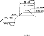
Figure 15 is an example of expression reflow soldering temperature curve.In this case, the measurement temperature is the central temperature on the preferred circuit plate, but as can obviously seeing from this temperature curve, the electroacoustic transducing device of installing on circuit board is because of being subjected to sizable heating, so can not ignore the demagnetization of magnet 120.
If such demagnetization takes place, the magnetic knot between the vibrating diaphragm 104 and unshakable in one's determination 116 makes a concerted effort just to reduce so, and the sound equipment performance of electroacoustic transducing device is changed.Figure 16 represents the frequency characteristic (acoustic characteristic) of the preceding acoustic pressure of reflow soldering processing, Figure 17 represents the frequency characteristic (acoustic characteristic) of reflow soldering processing back acoustic pressure, Figure 18 represents the frequency characteristic of the preceding electric current of reflow soldering processing, and Figure 19 represents the frequency characteristic of reflow soldering processing after-current.That is to say that handling in the electroacoustic transducing device that heated with reflow soldering, the lowest resonance frequency of vibrating diaphragm 104 is lower, the acoustic pressure grade is also lower, and acoustic characteristic worsens.
Have, support component 102 is formed by nonmagnetic metal and resin etc. again.Support component 102 its material under the temperature about 80 ℃ that forms with this material produces expansion with its linear expansion coefficient that has, but shrinks by life size at normal temperatures.But under the reflow soldering treatment temperature, the support component 102 that forms with resin is because thermal processes act or thermal degradation when produce dimensional contraction.The shrinkage of LCP material as shown in figure 20.It is big that this degree changes for material, in general, and the material price height that thermal contraction is low.
And, if producing, the heating that support component 102 is handled because of reflow soldering shrinks, and the iron core 116 of this part and the air gap 122 between the vibrating diaphragm 104 will narrow down so, and the magnetic knot between the vibrating diaphragm 104 of this part and unshakable in one's determination 116 closes and will increase.The relation that the material of table 1 expression support component 102 and air gap change, Figure 12 represents to handle along with reflow soldering the variation of air gap.
Table 1
| Pattern | Moulding material | Initial value | After the Reflow Soldering | Change | Air gap is (single: μ m) |
| A A A A A A A A A A A A A A A | VECTRA | 191 | 191 | 0 | |
| 192 | 192 | 0 | |||
| 193 | 193 | 0 | |||
| 191 | 191 | 0 | Average 0.0 | ||
| 188 | 188 | 0 | δn-1 | ||
| XREC | 189 | 186 | -3 | ||
| 188 | 187 | -1 | |||
| 192 | 192 | 0 | |||
| 187 | 184 | -3 | Average-2.0 | ||
| 186 | 183 | -3 | δ-1 1.41 | ||
| AMODEL | 190 | 188 | -2 | ||
| 190 | 189 | -1 | |||
| 195 | 193 | -2 | |||
| 189 | 186 | -3 | Average-2.2 | ||
| 193 | 190 | -3 | δn-1 0.84 | ||
| B B B B B | VECTRA | 163 | 160 | -3 | |
| 155 | 150 | -5 | |||
| 133 | 114 | -19 | |||
| 152 | 154 | 2 | Average-5.8 | ||
| 164 | 160 | -4 | δ-1 7.85 |
Be the harmful effect of avoiding causing, should adopt the low magnet of irreversible demagnetization rate to make the low resin of magnet 120 and shrinkage or metal etc. and make support component 102 because of this reflow soldering treatment temperature.There is the high problem of component costs of electroacoustic transducing device in its result.
Summary of the invention
Therefore, the object of the present invention is to provide the electroacoustic transducing device that can prevent to handle the sound equipment performance degradation that causes because of reflow soldering.
For achieving the above object, as Fig. 1~shown in Figure 12, the present invention utilizes the demagnetization of the irreversible demagnetization that has at reflow soldering treatment temperature lower magnet (10) and the shrinkage that has at reflow soldering treatment temperature lower support parts (20), the reduction of the lowest resonance frequency Fo that causes demagnetizing because of magnet (10) is cancelled out each other with the rising of vibrating diaphragm (22) the lowest resonance frequency Fo that the thermal contraction because of support component (20) causes, suppress the variation of the lowest resonance frequency Fo of vibrating diaphragm (22), realize the stabilisation of sound equipment performance.
According to scheme 1 described electroacoustic transducing device, comprising: the iron core (16) of winding around (18); The vibrating diaphragm (22) that receives the oscillating magnetic field of this iron core generation and vibrate; Support the support component of vibrating diaphragm, it makes and is provided with air gap (24) between described iron core and the described vibrating diaphragm; And magnet, it is located at the inboard of this support component, make the action of a magnetic field in described vibrating diaphragm, by to make the electrical signal conversion that adds to coil be oscillating magnetic field and act on described vibrating diaphragm, with electrical signal conversion is sound, it is characterized in that, is used in the magnetic material that presents irreversible demagnetization under the reflow soldering treatment temperature and forms described magnet, and, be used in the material that contraction is arranged under the reflow soldering treatment temperature and form described support component.According to this structure, the reduction of the vibrating diaphragm lowest resonance frequency Fo that can cause demagnetizing because of magnet cancels out each other the rising of vibrating diaphragm lowest resonance frequency Fo with the thermal contraction because of support component, can suppress the variation of the lowest resonance frequency Fo of vibrating diaphragm, realize the stabilisation of sound equipment performance.
According to scheme 2 described electroacoustic transducing devices, it is characterized in that, form described magnet with the SmCo series of magnets or with the neodymium series of magnets.By using such ferromagnetic material to make magnet, but the irreversible demagnetization that the thermal contraction balance of utilizing support component produces because of the heating of reflow soldering treatment temperature.
In addition,, it is characterized in that, form described support component with synthetic resin according to scheme 3 described electroacoustic transducing devices.By using such resin material to make support component, but the thermal contraction that utilizes the demagnetization balance of magnet that the heating because of the reflow soldering treatment temperature is produced.
And,, it is characterized in that described reflow soldering treatment temperature is 200~250 ℃ according to scheme 4 described electroacoustic transducing devices.Common reflow soldering treatment temperature is 200~250 ℃, temperature for this scope, the reduction of the vibrating diaphragm lowest resonance frequency Fo that can cause demagnetizing because of magnet cancels out each other the rising of the frequent rate Fo of the minimum resonance of vibrating diaphragm with the thermal contraction because of support component, can suppress the variation of vibrating diaphragm lowest resonance frequency Fo.
Have again,, will know from experience further clear and definite purpose of the present invention, feature, advantage etc. by with reference to the embodiment and example and the accompanying drawing that describe in detail below.
Description of drawings
Fig. 1 is the plane graph of the partial cut of expression electroacoustic transducing device one embodiment of the present invention.
Fig. 2 is the bottom view of expression electroacoustic transducing device shown in Figure 1.
Fig. 3 is the cutaway view of expression along the III-III line of electroacoustic transducing device shown in Figure 2.
Fig. 4 is the cutaway view of expression along the IV-IV line of electroacoustic transducing device shown in Figure 2.
Fig. 5 is that expression is because the figure that the total magnetic flux of front and back changes the change characteristic of the lowest resonance frequency that produces is handled in the reflow soldering of electroacoustic transducing device of the present invention.
Fig. 6 is the figure of the heat demagnetization rate before and after the reflow soldering of expression electroacoustic transducing device of the present invention is handled.
Fig. 7 is the figure of expression because of the lowest resonance frequency change characteristic of the air gap change generation before and after the reflow soldering processing of electroacoustic transducing device of the present invention.
Fig. 8 is the air gap change performance plot before and after the reflow soldering of expression electroacoustic transducing device of the present invention is handled.
Fig. 9 changes the figure that makes the lowest resonance frequency change and make lowest resonance frequency change synergism effect because of the air gap change because of total magnetic flux before and after the reflow soldering of expression electroacoustic transducing device of the present invention is handled.
Figure 10 is that expression is handled the figure that front and back total magnetic flux change makes the lowest resonance frequency change and makes lowest resonance frequency change synergism effect because of the air gap change because of the reflow soldering of electroacoustic transducing device of the present invention.
Figure 11 be expression because of the reflow soldering of existing electroacoustic transducing device handle before and after the lowest resonance frequency change that produces of total magnetic flux change characteristic and make the figure of the characteristic that lowest resonance frequency changes because of the air gap change.
Figure 12 is that expression is handled the figure that the front and back total magnetic flux changes the characteristic of the lowest resonance frequency change that is produced and makes the characteristic of lowest resonance frequency change because of the air gap change because of the reflow soldering of existing electroacoustic transducing device.
Figure 13 is the longitudinal sectional view of the existing electroacoustic transducing device of expression.
Figure 14 is the bottom view of the electroacoustic transducing device of expression Figure 13.
Figure 15 is the temperature profile of expression reflow soldering treatment temperature.
Figure 16 is the frequency characteristic figure of acoustic pressure before the reflow soldering of the existing electroacoustic transducing device of expression is handled.
Figure 17 is the frequency characteristic figure that the back acoustic pressure is handled in the reflow soldering of the existing electroacoustic transducing device of expression.
Figure 18 is the frequency characteristic figure of electric current before the reflow soldering of the existing electroacoustic transducing device of expression is handled.
Figure 19 is the frequency characteristic figure that after-current is handled in the reflow soldering of the existing electroacoustic transducing device of expression.
Figure 20 is the figure of the thermal contraction that produces of the heat treatment of the support component that uses in the electroacoustic transducing device of expression.
Figure 21 is the figure of the air gap change after reflow soldering is handled in the expression electroacoustic transducing device.
Embodiment
Below, with reference to accompanying drawing, describe the electroacoustic transducing device of the embodiment of the invention in detail.
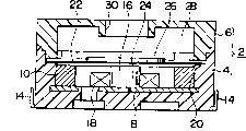
Fig. 1 to Fig. 4 represents an embodiment of electroacoustic transducing device of the present invention, and Fig. 1 represents to cut the plane graph of a part of electroacoustic transducing device, and Fig. 2 is its back view, and Fig. 3 is the cutaway view of the III-III line of Fig. 2, and Fig. 4 is the cutaway view of IV-IV line.
Two shell sheets 4,6 that shell 2 usefulness are made rectangle constitute, and all are the formed body of synthetic resin, with ultrasonic bonding etc. both are fixed as one.Shell sheet 4 can form with various manufacturing process, such as, constitute the base plate part on the lead frame.In the present embodiment, shell sheet 4 is formed base plate part, and insert shaping base plate 8, magnet 10 and lead terminal 12,14.
Have, iron core 16 is a concentric circles with magnet 10 again, and the position of magnet 10 is by determining at the shell sheet 4 inboard support components that form 20.This support component 20 also can constitute with the miscellaneous part that is different from shell sheet 4, and in the present embodiment, support component and shell sheet 4 form as one.Thereby support component 20 also constitutes with same synthetic resin with shell sheet 4.Using the parts different to constitute under the situation of support component 20, can select the resin material different, under the sort of situation, by inserting or shape also can be integrated with shell sheet 4 with shell sheet 4 with shell sheet 4.
And, on the top of support component 20 vibrating diaphragm 22 is set.Vibrating diaphragm 22 is the vibrating mass that constitutes with magnetic material, is used to respond the magnetic from unshakable in one's determination 16.Formation air gap 24 between this vibrating diaphragm 22 and unshakable in one's determination 16, the width of this air gap 24 utilize the height height of the aspect ratio support component 20 that makes iron core 16 by the relative value decision of support component 20 with the height of iron core 16, can form the air gap 24 with desired width.
By such air gap 24, act on vibrating diaphragm 22 by unshakable in one's determination 16 oscillating magnetic fields that produce, vibrating diaphragm 22 is had an effect with the magnetic field that the magnet 10 that forms closed magnetic circuit produces in vibrating diaphragm 22, and its result is because oscillating magnetic field vibrating diaphragm 22 vibrates on above-below direction.As the device that strengthens this oscillating mass, magnetic sheet 26 is installed at the middle body of vibrating diaphragm 22.
And on vibrating diaphragm 22, forming with shell sheet 6 is the resonant chamber 28 in sympathetic response space.This resonant chamber 28 utilizes the louver 30 that forms in shell sheet 6 outwards open.By sound sympathetic response in resonant chamber 28 that the vibration of vibrating diaphragm 22 produces, mainly outwards emit from louver 30.
For this electroacoustic transducing device, be used in the magnetic material that presents irreversible demagnetization under the reflow soldering treatment temperature about 200 ℃~250 ℃ and form magnet 10.As the one example, be listed below.
I. isotropism SmCo sintering 1-5 series
Ii. isotropism SmCo sintering 2-17 series
Iii. neodymium series bonded permanent magnet
Iv. samarium series bonded permanent magnet
In such electroacoustic transducing device, be used in the synthetic resin that shrinks under the reflow soldering treatment temperature about 200 ℃~250 ℃ and form support component 20.That is to say, in the present embodiment since with shell sheet 4 one that be base plate part, shell 2 itself is just with this synthetic resin formation.Example as its synthetic resin is listed below:
A.LCP-1, vectra (Vectra) AE130i
B.LCP-2, vectra (Vectra) AE130i
B. nylon 6T, aromatic hydrocarbons 230
c.PPS,C-100HG
Can at random make up with the magnet 10 of such material formation and the material of support component 20, but in the change of the lowest resonance frequency Fo that suppresses vibrating diaphragm 22, have only combination.
According to such structure, under the situation that is subjected to the heating of reflow soldering treatment temperature, utilize the irreversible demagnetization in magnet 10, make the magnetic knot between vibrating diaphragm 22 and unshakable in one's determination 16 make a concerted effort to reduce, acoustic characteristic changes.Specifically, in general the variation of the lowest resonance frequency Fo of vibrating diaphragm 22 is that its value reduces, and produces the result who reduces acoustic pressure thus, and acoustic characteristic is had considerable influence.
In addition, under the situation that is subjected to the end heating of reflow soldering processing temperature, produce thermal contraction in support component 20, its result reduces the width of air gap 24.If the narrowed width of this air gap 24 will make the magnetic knot between vibrating diaphragm 22 and unshakable in one's determination 16 make a concerted effort to improve, its result uprises the lowest resonance frequency Fo of vibrating diaphragm 22, that is to say that acoustic characteristic is had considerable influence.This variation has opposite relation with the demagnetization of magnet 10.
Thereby, utilize the demagnetization of magnet 10 to make lowest resonance frequency Fo reduction and utilize the thermal contraction of support component 20 that lowest resonance frequency Fo rising is cancelled out each other, become complementary result, utilize the combined effect of the material relation of magnet 10 and support component 20, even be subjected to the heating of reflow soldering treatment temperature, also can obtain not make effectively the good result of lowest resonance frequency Fo change.
Below, the embodiment of the electroacoustic transducing device of key diagram 1~shown in Figure 4.
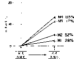
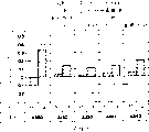
Fig. 5 is illustrated in the change of the lowest resonance frequency Fo of the vibrating diaphragm 22 before and after the reflow soldering processing under the situation that changes magnet 10 materials.Among Fig. 5, M1 represents to adopt the characteristic under the isotropism SmCo sintering 1-5 series situation, M2 represents to adopt the characteristic under the isotropism SmCo sintering 2-17 series situation, M3 represents to adopt the characteristic under the neodymium series bonded permanent magnet situation, M4 represents to adopt the characteristic under the samarium series bonded permanent magnet situation, owing to be subjected to the heating of reflow soldering treatment temperature, the change value of lowest resonance frequency Fo reduces 22Hz under the M1 situation, under the M2 situation, reduce 42Hz, under the M3 situation, reduce 94Hz, under the M4 situation, reduce 104Hz.
In addition, Fig. 6 represents the total magnetic flux change of the reflow soldering processing front and back of corresponding characteristic shown in Figure 5.Because be subjected to the heating of reflow soldering treatment temperature, its hot demagnetization rate is 2.8% under the M1 situation, is 5.2% under the M2 situation, is 11.7% under the M3 situation, is 13.5% under the M4 situation.
Then, Fig. 7 is illustrated under the situation of change support component 20 materials the change of the lowest resonance frequency Fo of the vibrating diaphragm 22 that the width variation because of the air gap 24 of reflow soldering before and after handling produces.Among Fig. 7, C1 represents to adopt LCP-1, vectra (Vectra) E130i, penetrate each characteristic of pressing under the situation about being shaped for 40kg/cm3 by being shaped, C2 represents to adopt LCP-2, vectra (Vectra) E130i, penetrate each characteristic of pressing under the situation about being shaped for 130kg/cm3 by being shaped, C3 represents to use each characteristic under nylon 6T, aromatic hydrocarbons 230 situations, and C4 represents to use each characteristic under PPS, the C-100HG situation, and C0 represents to use each characteristic under the brass situation.Among Fig. 7, the change value of lowest resonance frequency Fo is 40Hz under the C1 situation, is 56Hz under the C2 situation, is 80Hz under the C3 situation, is 112Hz under the C4 situation.
In addition, as shown in Figure 8, owing to be subjected to the change of the air gap 24 that the heating of reflow soldering treatment temperature causes and be 0 under the C0 situation (, be-5 under the C1 situation (, be-7 under the C2 situation (, be-10 under the C3 situation (, be-14 under the C4 situation (, any variation does not take place under the brass situation, but can find out, forming with resin under the situation of support component 20, can obviously reduce according to the value of its kind air gap 24.
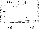
Therefore, corresponding by the total magnetic flux change part that magnet 10 produces with the change part of air gap 24, so the lowest resonance frequency Fo value that causes because of the demagnetization of magnet 10 reduce can utilize air gap 24 reduce lowest resonance frequency Fo is increased compensate.If will see this synergism effect, can be referring to Fig. 9.That is to say, if make M1 and C1, M2 and C2, M3 and C3 or M4 corresponding with C4, so the lowest resonance frequency Fo that causes because of the demagnetization of magnet 10 reduce cancel out each other with increase because of the lowest resonance frequency Fo that reduces to cause of air gap 24, the result of compensation makes the amplitude of fluctuation Δ F of the lowest resonance frequency Fo of vibrating diaphragm 22 become very little compensating value.
For example, as shown in figure 10, in the material of support component 20 is that the material of nylon 6T, magnet 10 is under the situation of neodymium series bonded permanent magnet, because of causing magnet 10 demagnetizations, the heating that is subjected to the reflow soldering treatment temperature makes the reducing of lowest resonance frequency Fo of vibrating diaphragm 22, the lowest resonance frequency Fo of vibrating diaphragm 22 is increased to be compensated, its result, the amplitude of fluctuation Δ F of lowest resonance frequency Fo is very little, is significantly less than the amplitude of fluctuation Δ F of Figure 20 and the lowest resonance frequency Fo with existing quality characteristic shown in Figure 21.
Therefore, in Figure 11, Figure 13 and electroacoustic transducing device shown in Figure 14, represented to use brass on the support component 20, on magnet 10, used the characteristic of the lowest resonance frequency Fo of the vibrating diaphragm 22 in the neodymium series magnet case.M3 represent because of reflow soldering handle before and after the change of lowest resonance frequency Fo of the vibrating diaphragm 22 that causes of the demagnetization of magnet 10, C0 represents the change of the lowest resonance frequency Fo that the change because of air gap 24 causes.In this structure, it is big that the amplitude of fluctuation Δ F of lowest resonance frequency Fo obviously becomes.
In addition, in Figure 12, Figure 13 and electroacoustic transducing device shown in Figure 14, represented to use brass on the support component 20, on magnet 10, used the characteristic of the lowest resonance frequency Fo of the vibrating diaphragm 22 in the isotropism SmCo sintering 2-17 series of magnets situation.M1 represent because of reflow soldering handle before and after the change of lowest resonance frequency Fo of the vibrating diaphragm 22 that causes of the demagnetization of magnet 10, C0 represents the change of the lowest resonance frequency Fo that the change because of air gap 24 causes.In this combination, the amplitude of fluctuation Δ F of lowest resonance frequency Fo becomes near characteristic shown in Figure 10, but has the material problem of ultra-high price.
Have again, though material and the combination thereof to magnet 10 and support component 20 is illustrated in an embodiment, but the present invention is not limited to these materials and its combination, can also adopt following material and its combination, promptly the lowest resonance frequency Fo that causes because of the demagnetization of magnet 10 reduce can make lowest resonance frequency Fo increase material and the combination thereof that compensates by the shrinkage of utilizing support component 20.
As top explanation,, can obtain following effect according to the present invention.
The variation that the magnetic knot that the change of the vibrating diaphragm that causes because of the reflow soldering treatment temperature and the air gap between the iron core is followed is made a concerted effort compensates accordingly with the demagnetization variation of magnet, the reduction of the sound equipment performance that causes because of the reflow soldering treatment temperature can be prevented, the stabilisation of sound equipment performance can be realized.
B. the thermal contraction by support component, can enough vibrating diaphragms and iron core between air gap change variation that caused magnetic knot makes a concerted effort and compensate some demagnetization in the magnet thermal degradation when that causes because of the reflow soldering treatment temperature.
C. owing to the change of the magnet demagnetization that needn't suppress to cause and the thermal contraction of support component etc.,, reduce manufacturing cost so can use low-cost material because of the reflow soldering treatment temperature.
And, though discussed structure, effect and the effect of the preferred embodiment of the present invention, but electroacoustic transducing device of the present invention is not limited to the foregoing description and example, it comprises according to purpose of the present invention and embodiment can infer all structures that various structures, distortion and those skilled in the art of can predict.
Claims (11)
1. one kind is installed in electroacoustic transducing device on the electronic equipment with Reflow Soldering, comprises following each several part:
An iron core;
A coil is wound on the described iron core;
A vibrating diaphragm is subjected to the effect of the described alternating magnetic field that produces unshakable in one's determination and vibrates;
A support component is supporting vibrating diaphragm, makes between vibrating diaphragm and the iron core and forms the space, and this support component is made by the material that quantitatively shrinks with the temperature of Reflow Soldering;
A magnet is located at the support component inboard, and with so that fixed magnetic field acts on the vibrating diaphragm, the electric signal that is added to coil converts sound by converting action of alternating magnetic field to to vibrating diaphragm;
Described magnet is made by the material that produces irreversible demagnetizing effect with the Reflow Soldering temperature;
Described contraction and described demagnetizing effect cancel each other out, thereby make the sound property of electroacoustic transducing device before and after Reflow Soldering keep stable.
2. electroacoustic transducing device as claimed in claim 1 is characterized in that described magnet is made by the SmCo series of magnets.
3. electroacoustic transducing device as claimed in claim 1 is characterized in that described support component is made by synthetic resin.
4. electroacoustic transducing device as claimed in claim 1 is characterized in that, the temperature of Reflow Soldering is 200~250 ℃.
5. electroacoustic transducing device as claimed in claim 1 is characterized in that described magnet is made by the neodymium series of magnets.
6. a method of making electroacoustic transducing device comprises the following steps:
Coil is wound up on the iron core;
In with respect to the space of described iron core, dispose support component along axis direction;
Vibrating diaphragm is placed in to make on the support component between vibrating diaphragm and the iron core forms the space, described vibrating diaphragm is flow through the effect of alternating magnetic field unshakable in one's determination and is vibrated;
In the support component inboard, the fixed magnetic field of magnet is affacted on the vibrating diaphragm magnet configuration, the electric signal that is added to coil converts sound by converting action of alternating magnetic field to to vibrating diaphragm;
Electroacoustic transducing device is carried out reflow process, and at this moment described magnet produces irreversible demagnetizing effect with the temperature of Reflow Soldering, and described support component quantitatively shrinks with the temperature of Reflow Soldering, and contraction and demagnetizing effect cancel each other out, thereby draw stable voice output.
7. method as claimed in claim 6 is characterized in that, the contraction of described support component changes the space between vibrating diaphragm and the iron core.
8. method as claimed in claim 6 is characterized in that described magnet is made by the SmCo series of magnets.
9. method as claimed in claim 6 is characterized in that described magnet is made by the neodymium series of magnets.
10. method as claimed in claim 6 is characterized in that described support component is made by synthetic resin.
11. method as claimed in claim 6 is characterized in that, the temperature of Reflow Soldering is 200~250 ℃.
Applications Claiming Priority (3)
| Application Number | Priority Date | Filing Date | Title |
|---|---|---|---|
| JP30941596A JP3532715B2 (en) | 1996-11-20 | 1996-11-20 | Electromagnetic acoustic transducer |
| JP309415/96 | 1996-11-20 | ||
| JP309415/1996 | 1996-11-20 |
Publications (2)
| Publication Number | Publication Date |
|---|---|
| CN1193885A CN1193885A (en) | 1998-09-23 |
| CN1132500C true CN1132500C (en) | 2003-12-24 |
Family
ID=17992736
Family Applications (1)
| Application Number | Title | Priority Date | Filing Date |
|---|---|---|---|
| CN97126389A Expired - Fee Related CN1132500C (en) | 1996-11-20 | 1997-11-20 | Electromagnetic acoustic transducer |
Country Status (4)
| Country | Link |
|---|---|
| US (1) | US6023519A (en) |
| JP (1) | JP3532715B2 (en) |
| KR (1) | KR100451481B1 (en) |
| CN (1) | CN1132500C (en) |
Families Citing this family (6)
| Publication number | Priority date | Publication date | Assignee | Title |
|---|---|---|---|---|
| DK173789B1 (en) * | 1998-10-05 | 2001-10-22 | Kirk Acoustics As | Electroacoustic communication device |
| JP3660843B2 (en) * | 1999-12-24 | 2005-06-15 | スター精密株式会社 | Electromagnetic acoustic transducer and manufacturing method thereof |
| SE516270C2 (en) * | 2000-03-09 | 2001-12-10 | Osseofon Ab | Electromagnetic vibrator |
| JP2002149162A (en) * | 2000-08-30 | 2002-05-24 | Star Micronics Co Ltd | Electromagnetic acoustic converter |
| CN102577434A (en) * | 2009-04-10 | 2012-07-11 | 伊默兹公司 | Systems and methods for acousto-tactile speakers |
| US10469950B2 (en) * | 2017-09-25 | 2019-11-05 | Harman International Industries, Incorporated | Acoustic transducer and magnetizing current controller |
Family Cites Families (6)
| Publication number | Priority date | Publication date | Assignee | Title |
|---|---|---|---|---|
| CH642504A5 (en) * | 1981-06-01 | 1984-04-13 | Asulab Sa | Hybrid electroacoustic transducer |
| JPS6129298A (en) * | 1984-07-19 | 1986-02-10 | Matsushita Electric Ind Co Ltd | Piezoelectric transducer |
| CN1038179C (en) * | 1992-09-30 | 1998-04-22 | 星精密株式会社 | Electro-acoustic converter |
| JP2728622B2 (en) * | 1993-05-04 | 1998-03-18 | スター精密株式会社 | Electroacoustic transducer |
| JP2862802B2 (en) * | 1994-10-03 | 1999-03-03 | スター精密株式会社 | Small sounding body |
| JPH08102998A (en) * | 1994-10-03 | 1996-04-16 | Star Micronics Co Ltd | Manufacture of electromagnetic acoustic transducer |
-
1996
- 1996-11-20 JP JP30941596A patent/JP3532715B2/en not_active Expired - Fee Related
-
1997
- 1997-11-12 US US08/968,501 patent/US6023519A/en not_active Expired - Fee Related
- 1997-11-15 KR KR1019970060285A patent/KR100451481B1/en not_active Expired - Fee Related
- 1997-11-20 CN CN97126389A patent/CN1132500C/en not_active Expired - Fee Related
Also Published As
| Publication number | Publication date |
|---|---|
| JPH10149169A (en) | 1998-06-02 |
| KR100451481B1 (en) | 2004-12-10 |
| US6023519A (en) | 2000-02-08 |
| CN1193885A (en) | 1998-09-23 |
| JP3532715B2 (en) | 2004-05-31 |
| KR19980042470A (en) | 1998-08-17 |
Similar Documents
| Publication | Publication Date | Title |
|---|---|---|
| CN1225076C (en) | Linear motor and compressor with linear motor | |
| CN1163104C (en) | Loudspeaker and magnetic circuit used by same | |
| CN1038179C (en) | Electro-acoustic converter | |
| CN1040606C (en) | Electracoustic transducer and method of fabricating the same | |
| WO2022183801A1 (en) | Loudspeaker and electronic device | |
| CN1132500C (en) | Electromagnetic acoustic transducer | |
| WO2004017677A2 (en) | Subwoofer | |
| CN1509119A (en) | Push-push multiple magnetic air gap transducer | |
| CN1255002C (en) | Loudspeaker device | |
| CN1123511A (en) | Electroustic transducer | |
| CN102204278A (en) | Moving magnet loudspeaker and manufacturing method thereof | |
| CN1499483A (en) | Electromagnetic electroacoustic converter | |
| CN1151702C (en) | Electromagnetic voice converter | |
| CN1290115A (en) | Loudspeaker system and cooling device | |
| CN1250044C (en) | Loudspeaker and loudspeaker system | |
| CN1038095C (en) | Temperature compensation of sound pressure characterastics of electric sound inverter | |
| CN101803403B (en) | Ultra slim type acoustic transducer | |
| CN1106134C (en) | Manufacturing method of electromagnetic sound converter and electronic device using the converter | |
| HK1016009A (en) | Electroacoustic transducer | |
| CN1087584C (en) | Electromagnetic sound converter and electronic apparatus using same | |
| CN1819709A (en) | Speaker diaphragm, speaker unit and speaker apparatus | |
| JP2000102094A (en) | Speaker | |
| CN1356852A (en) | A kind of loudspeaker suspension edge and its loudspeaker | |
| CN221575601U (en) | Flat magnetic horn structure | |
| CN221306105U (en) | Speaker components and electronics |
Legal Events
| Date | Code | Title | Description |
|---|---|---|---|
| C06 | Publication | ||
| PB01 | Publication | ||
| C10 | Entry into substantive examination | ||
| SE01 | Entry into force of request for substantive examination | ||
| C10 | Entry into substantive examination | ||
| SE01 | Entry into force of request for substantive examination | ||
| C14 | Grant of patent or utility model | ||
| GR01 | Patent grant | ||
| REG | Reference to a national code |
Ref country code: HK Ref legal event code: WD Ref document number: 1016009 Country of ref document: HK |
|
| C17 | Cessation of patent right | ||
| CF01 | Termination of patent right due to non-payment of annual fee |
Granted publication date: 20031224 Termination date: 20101120 |