Oil-gas separation filter applied to automobile engine
Technical Field
The invention relates to the field of oil-gas separation filters, in particular to an oil-gas separation filter applied to an automobile engine.
Background
The oil-gas separator is a device for separating crude oil produced by an oil well from associated natural gas, can be applied to an automobile engine, can cause a part of mixed gas containing fuel oil, engine oil and water vapor due to gaps among a cylinder wall, a piston and a piston ring, and can cause the waste of the fuel oil and the engine oil.
Disclosure of Invention
The invention aims to provide an oil-gas separation filter applied to an automobile engine, which has multi-stage separation and is beneficial to improving the oil-gas separation effect.
In order to achieve the purpose, the technical scheme of the invention is as follows:
the utility model provides a be applied to automobile engine's oil-gas separation filter, includes shell, a plurality of baffle, feed inlet, oil-out, the shell is the cavity casing, including oil gas room, separation chamber and the oil storage chamber by last down setting in the shell, the oil storage chamber passes through the oil-out and forms the oil passageway, the oil gas room passes through the feed inlet and is connected with the external world, the baffle is including the coaxial cascaded baffle of locating in the separation chamber to and locate the multilayer flow distribution plate of separation chamber inside wall, the top of cascaded baffle with the top surface rotates in the separation chamber to be connected, the multilayer the flow distribution plate is in vertical direction dislocation set, the oil gas room pass through the fuel injection valve with the separation chamber intercommunication, the nozzle orientation of fuel injection valve the lateral surface of cascaded baffle.
Preferably, before oil gas in an external device enters an oil gas chamber, a defoaming agent is put into the device and mixed with the oil gas, wherein the defoaming agent comprises, by weight, 10-20 parts of polydimethylsiloxane, 5-12 parts of nonylphenol polyoxyethylene ether, 1-5 parts of polyacrylamide, 20-30 parts of zeolite powder and 15-25 parts of an emulsifier.
More preferably, the defoaming agent comprises, by weight, 13-17 parts of polydimethylsiloxane, 8-10 parts of nonylphenol polyoxyethylene ether, 3-4 parts of polyacrylamide, 23-28 parts of zeolite powder, 18-23 parts of emulsifying agent and 3-17 parts of a surfactant, wherein the polydimethylsiloxane has excellent physical properties and can be rapidly diffused on the surface of oil gas to facilitate the elimination of bubbles on the surface of the oil gas, the nonylphenol polyoxyethylene ether has excellent permeability and is favorable for the mixed contact of the defoaming agent and the oil gas, the polyacrylamide has excellent chemical activity and can exert a foam inhibition performance for a long time, the zeolite powder has an excellent adsorption function and is favorable for the adsorption and separation of gas in the oil gas, and the emulsifying agent has the performance of inhibiting and eliminating bubbles.
Preferably, the stepped partition plate comprises a rotating rod arranged on the central shaft and a plurality of round tables with diameters sequentially increasing from bottom to top, the round tables are coaxially arranged, a sealing cover for mounting the motor is arranged at the inner top of the separation chamber, a rotating shaft of the motor extends into the separation chamber, and the rotating rod is in transmission connection with the rotating shaft of the motor.
Preferably, the round platform is equipped with six the round platform is hollow shell, be equipped with the strengthening rib with the round platform one-to-one on the lateral surface of bull stick, the one end of strengthening rib and the lateral surface welding of pivot, the other end of strengthening rib and the inside wall welding of round platform.
Preferably, the number of the oil injection valves is two, the oil injection valves are arranged on two sides of the top surface in the separation chamber, and the two oil injection valves are respectively located on two sides of the top of the stepped partition plate.
Preferably, the multilayer flow distribution plate comprises a flow distribution plate first layer, a flow distribution plate second layer and a flow distribution plate third layer which are arranged from top to bottom.
Preferably, the cross section of shell is circular, the first layer of flow distribution plate includes three first reposition of redundant personnel unit, and is three first reposition of redundant personnel unit becomes the circumference and arranges and the contained angle between the adjacent first reposition of redundant personnel unit is 120 degrees, the flow distribution plate second floor includes three second reposition of redundant personnel unit, and is three the second reposition of redundant personnel unit becomes the circumference and arranges and the contained angle between the adjacent second reposition of redundant personnel unit is 120 degrees, the flow distribution plate third layer includes three third reposition of redundant personnel unit, and is three the third reposition of redundant personnel unit becomes the circumference and arranges and the contained angle between the adjacent third reposition of redundant personnel unit is 120 degrees, and in the vertical direction, the contained angle of adjacent first reposition of redundant personnel unit and second reposition of redundant personnel unit is 40 degrees, and the contained angle of adjacent second reposition of redundant personnel unit and third reposition of redundant personnel unit is 40 degrees, and the contained angle of adjacent third reposition of redundant personnel unit and first reposition of redundant personnel unit is 40 degrees.
Preferably, the top surfaces of the first flow dividing unit, the second flow dividing unit and the third flow dividing unit are provided with inclined surfaces with the same inclination, and each inclined surface faces the same side uniformly.
Preferably, the top surfaces of the first flow dividing unit, the second flow dividing unit and the third flow dividing unit are provided with arc surfaces with the same radius, and each inclined surface faces the same side uniformly.
Preferably, the first flow dividing unit, the second flow dividing unit and the third flow dividing unit are provided with a plurality of flow dividing holes penetrating through the top surface and the bottom surface.
Preferably, a separation net and an exhaust valve are further arranged between the separation chamber and the oil storage chamber, an air passage is formed between the separation chamber and the outside through the exhaust valve, and the bottom surface of the oil storage chamber is a conical surface facing the separation net.
The invention has the beneficial effects that: the oil gas is sprayed on the rotatable stepped partition plate in the first step, in the process of spraying the oil gas, the motor controls the stepped partition plate to rotate at a low speed, the oil gas is attracted by gravity, and slides down along the stepped spiral from top to bottom to play a role in prolonging the movement track of the oil gas, when the outer side of the stepped partition plate is covered with oil in the second step, the oil injection valve stops working, the motor controls the stepped partition plate to rotate at a high speed, the outer side face of the stepped partition plate is oiled through centrifugal force and is thrown onto a plurality of flow distribution plates on the inner side wall of the separation chamber, and a plurality of oil drops move on the flow distribution plates again, so that the effect of oil-gas separation is improved.
Additional aspects and advantages of the invention will be set forth in part in the description which follows and, in part, will be obvious from the description, or may be learned by practice of the invention.
Drawings
In order to more clearly illustrate the embodiments of the present invention or the technical solutions in the prior art, the drawings used in the description of the embodiments or the prior art will be briefly described below, and it is obvious that the drawings in the following description are only some embodiments of the present invention, and for those skilled in the art, other drawings can be obtained according to these drawings without creative efforts.
FIG. 1 is a schematic structural diagram of an oil-gas separation filter applied to an automobile engine in the invention;
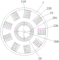
FIG. 2 is a layout view of a flow distribution plate of an oil-gas separation filter applied to an automobile engine in the invention;
FIG. 3 is a cross-sectional view of a beveled first splitter plate of an oil-gas separation filter for an automotive engine according to the present invention;
FIG. 4 is a sectional view of a first splitter plate with a circular arc surface of an oil-gas separation filter applied to an automobile engine in the invention;
shown in the figure: 1-shell, 10-oil gas chamber, 100-feed inlet, 101-oil outlet, 102-exhaust valve, 11, separation chamber, 110-oil injection valve, 111-nozzle, 112-motor, 113-sealing cover, 12, oil storage chamber, 120-separation net;
2-partition plate, 20-stepped partition plate, 200-rotating rod, 201-reinforcing rib, 21-first layer of flow distribution plate, 210-first flow distribution unit, 22-second layer of flow distribution plate, 220-second flow distribution unit, 23-third layer of flow distribution plate, 230-third flow distribution unit, 24-flow distribution hole, 25-inclined plane and 26-circular arc surface.
Detailed Description
The technical solutions in the embodiments of the present invention will be clearly and completely described below with reference to the drawings in the embodiments of the present invention, and it is obvious that the described embodiments are only a part of the embodiments of the present invention, and not all of the embodiments. All other embodiments, which can be derived by a person skilled in the art from the embodiments given herein without making any creative effort, shall fall within the protection scope of the present invention.
Example 1
Referring to fig. 1-4, in the embodiment of the present invention, an oil-gas separation filter applied to an automobile engine includes a housing 1, a plurality of partition plates, a feed inlet 100, and an oil outlet 101, where the housing 1 is a hollow casing, an oil-gas chamber 10, a separation chamber 11, and an oil storage chamber 12 are included in the housing 1, the oil storage chamber 12 forms an oil passage through the oil outlet 101, the oil outlet 101 is connected to an external engine, the oil-gas chamber 10 is connected to the outside through the feed inlet 100, the feed inlet 100 is connected to an external feeding device, the partition plates include a stepped partition plate 20 coaxially disposed in the separation chamber 11, and a plurality of splitter plates disposed on an inner side wall of the separation chamber 11, a top end of the stepped partition plate 20 is rotatably connected to an inner top surface of the separation chamber 11, the plurality of splitter plates are disposed in a staggered manner in a vertical direction, and the oil-gas chamber 10 is communicated with the separation chamber 11 through an oil injection valve 110, the nozzle 111 of the injection valve 110 faces the outer side face of the stepped diaphragm 20.
Preferably, before oil gas in an external device enters an oil gas chamber, a defoaming agent is put into the device, the defoaming agent is mixed with the oil gas, and the oil gas in the external device is primarily separated, wherein the defoaming agent comprises the following components, by weight, 10 parts of polydimethylsiloxane, 5 parts of nonylphenol polyoxyethylene ether, 1 part of polyacrylamide, 20 parts of zeolite powder and 15 parts of an emulsifier.
Preferably, the stepped partition plate 20 includes a rotating rod 200 disposed on the central axis and a plurality of circular truncated cones having diameters gradually increasing from bottom to top, the circular truncated cones are coaxially disposed, a sealing cover 113 for mounting the motor 112 is disposed at the inner top of the separation chamber 11, a rotating shaft of the motor 112 extends into the separation chamber 11, and the rotating rod 200 is in transmission connection with the rotating shaft of the motor 112.
When the oil-gas separation device is used, firstly, the rotating shaft of the motor 112 and the rotating rod 200 are driven to drive the stepped partition plate 20 to rotate, then the rotation work of the motor 112 is a low-speed gear, then the oil injection valves 110 positioned at two sides of the separation chamber 11 start working, oil gas in the oil-gas chamber 10 is injected to the outer side surface of the stepped partition plate 20, and as the oil gas injection and the rotation of the stepped partition plate 20 are carried out simultaneously, the oil gas is simultaneously subjected to gravity when covering the outer side surface of the stepped partition plate and the friction force of the stepped partition plate 20 to the oil gas, so that the oil gas slides down along a step spiral from top to bottom on the outer side surface of the stepped partition plate 20 along with the rotation, and secondary oil-gas separation is carried out.
Preferably, six circular truncated cones of the stepped partition plate 20 are hollow shells, reinforcing ribs 201 corresponding to the circular truncated cones one by one are arranged on the outer side surfaces of the rotating rods 200, one ends of the reinforcing ribs 201 are welded with the outer side surfaces of the rotating shafts, and the other ends of the reinforcing ribs 201 are welded with the inner side walls of the circular truncated cones; so that each round platform is stressed uniformly when rotating, and the oil gas adhesion effect is favorably improved.
Preferably, there are two fuel injection valves 110, the fuel injection valves 110 are disposed on two sides of the inner top surface of the separation chamber 11, and the two fuel injection valves 110 are respectively disposed on two sides of the top of the stepped partition plate 20; is favorable for improving the oil gas injection efficiency.
Preferably, the plurality of layers of the flow distribution plates comprise a first layer 21 of the flow distribution plate, a second layer 22 of the flow distribution plate and a third layer 23 of the flow distribution plate, which are arranged from top to bottom.
Preferably, the cross section of the housing 1 is circular, the first layer 21 of the flow distribution plate comprises three first flow distribution units 210, the three first flow distribution units 210 are arranged in a circle, and the included angle between adjacent first flow distribution units 210 is 120 degrees, the second layer 22 of the flow distribution plate comprises three second flow distribution units 220, the three second flow distribution units 220 are arranged in a circle, the included angle between the adjacent second flow distribution units 220 is 120 degrees, the third layer 23 of the flow distribution plate comprises three third flow distribution units 230, the three third flow distribution units 230 are arranged in a circle, the included angle between adjacent third flow distribution units 230 is 120 degrees, in the vertical direction, the included angle between the adjacent first flow dividing unit 210 and the adjacent second flow dividing unit 220 is 40 degrees, the included angle between the adjacent second flow dividing unit 220 and the adjacent third flow dividing unit 230 is 40 degrees, and the included angle between the adjacent third flow dividing unit 230 and the first flow dividing unit 210 is 40 degrees.
When the outer surface of the stepped partition 20 is covered with oil, the oil injection valve 110 stops working, at this time, the rotation of the motor 112 is lifted to a high-speed gear, the outer side surface of the stepped partition 20 is oiled by the centrifugal force under the high-speed movement, and is thrown onto a plurality of flow distribution plates on the inner side wall of the separation chamber 11, and the three-layer flow distribution plate design enables most of the oil thrown from the stepped partition 20 to be attached to each flow distribution unit, thereby facilitating the secondary separation, and the oil thrown from the upper part of the stepped partition 20 is mostly scattered onto the first layer 21 of the flow distribution plates, and the track of the oil thrown from the upper part of the stepped partition 20 before being thrown is shorter than that of the lower part, so that the oil thrown from the first layer 21 of the flow distribution plates firstly finishes moving on one of the first flow distribution units 210, will slide down onto a certain second flow distribution unit 220 of the second layer 22 of the flow distribution plates, after passing through the second shunting unit 220, the oil gas finally slides onto a certain third shunting unit 230 of the third layer 23 of the shunting plate, so as to make up the movement track of the oil gas thrown outwards at the upper part of the stepped partition plate 20, so that the oil gas at each position is separated, and the three times of oil-gas separation is completed.
Preferably, the top surfaces of the first flow dividing unit 210, the second flow dividing unit 220 and the third flow dividing unit 230 are all provided with inclined surfaces 25 with the same inclination, and each inclined surface 25 faces the same side uniformly; the flow direction of the oil gas is fixed, and meanwhile, part of the oil gas is prevented from being detained on the flow dividing unit through the inclination.
Preferably, the top surfaces of the first flow dividing unit 210, the second flow dividing unit 220 and the third flow dividing unit 230 are all provided with arc surfaces 26 with the same radius, and each inclined surface 25 faces the same side uniformly; the arc surface 26 can prolong the oil-gas sliding time and is beneficial to improving the separation effect.
Preferably, the first flow dividing unit 210, the second flow dividing unit 220, and the third flow dividing unit 230 are all provided with a plurality of flow dividing holes 24 penetrating through the top surface and the bottom surface; the oil with smaller particle diameter is preferentially dropped into the oil storage chamber 12, and the separation time is saved.
Preferably, a separation net 120 and an exhaust valve 102 are further arranged between the separation chamber 11 and the oil storage chamber 12, the separation chamber forms an air passage with the outside through the exhaust valve 102, and the bottom surface of the oil storage chamber 12 is a conical surface facing the separation net 120; the third separation of oil and gas is performed through the fine apertures of the separation net 120, the purity of oil in the oil storage chamber 12 is further improved, and the exhaust valve 102 exhausts the excessive gas in the separation chamber 11.
Example 2
The present embodiment is different from embodiment 1 in that: the defoaming agent of the embodiment is prepared from the following components, by weight, 20 parts of polydimethylsiloxane, 12 parts of nonylphenol polyoxyethylene ether, 5 parts of polyacrylamide, 30 parts of zeolite powder and 25 parts of an emulsifier.
The rest of this embodiment is the same as embodiment 1, and will not be described herein again.
Example 3
The present embodiment is different from embodiment 1 in that: the defoaming agent of the embodiment is prepared from the following components, by weight, 15 parts of polydimethylsiloxane, 9 parts of nonylphenol polyoxyethylene ether, 3 parts of polyacrylamide, 15 parts of zeolite powder and 20 parts of an emulsifier.
The rest of this embodiment is the same as embodiment 1, and will not be described herein again.
It will be evident to those skilled in the art that the invention is not limited to the details of the foregoing illustrative embodiments, and that the present invention may be embodied in other specific forms without departing from the spirit or essential attributes thereof. The present embodiments are therefore to be considered in all respects as illustrative and not restrictive, the scope of the invention being indicated by the appended claims rather than by the foregoing description, and all changes which come within the meaning and range of equivalency of the claims are therefore intended to be embraced therein. Any reference sign in a claim should not be construed as limiting the claim concerned.