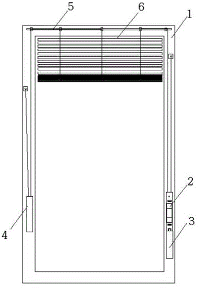
Automatic falling prevention shutter and method thereof
Technical Field
The invention relates to a blind window, in particular to a blind window capable of preventing automatic falling and a method thereof.
Background
The hollow glass built-in blind is a window belonging to the category of hollow glass products for sunshade, which is configured by installing blinds that can be raised and lowered as needed in two pieces of glass (inner glass and outer glass, which may be referred to as front glass and rear glass) that are installed in a state of facing each other and that close the peripheral edge portions, and has the following advantages: the heat insulation performance is good, thereby embodying the energy saving of the building; excellent sound insulation to prevent the noise from disturbing; the anti-condensation and anti-frost effects ensure sufficient indoor light and show the expected bright effect; the curtain piece of the blind is adjusted by the deflection angle, so that the required indoor lighting requirement is obtained, the privacy is protected, and the blind curtain piece (the habit is called as the curtain piece for short) is prevented from being polluted by dust, so that the excellent cleaning-free effect is embodied; the decorative effect is ideal for buildings so as to improve the grade of the buildings; the high-rise building has strong impact resistance, good safety and long service life, thereby meeting the installation requirement of high-rise buildings and the extremely long-term use maintenance-free requirement; simple, light and labor-saving to adapt to the operation of people of different ages and physical abilities, etc.
The common drive controller of the hollow glass built-in shutter is provided with two inner control mechanisms and two outer control mechanisms, wherein one of the two inner control mechanisms controls the turnover angle (inner turnover and outer turnover, also called front turnover and rear turnover) of a curtain sheet, the other one of the two inner control mechanisms controls the rope winding or rope unwinding of a lifting traction rope of the shutter, the two outer control mechanisms are respectively in magnetic attraction with the two inner control mechanisms through the inner glass, and the outer control mechanisms drive the inner control mechanisms through the operation of an operator on the outer control mechanisms. In order to avoid interference between the two outer actuating devices, it is common to provide two outer actuating devices and two inner actuating devices on each side of the window.
The grant number CN203547479U discloses a double-handle built-in shutter hollow glass, wherein the turning and lifting are respectively controlled by two handles, and the control mode is more accurate and clear in action. The aluminum alloy frame adopts the design of a European standard notch, and all plastic parts of the fixed or movable shutter are preset in the European standard notch. However, when the shutter is used, particularly when the length of the shutter exceeds 70cm, the weight of the shutter made of aluminum alloy is increased, so that the counter weight on the handle is increased, the moving effect of the handle is poor, the handle is heavy in hand feeling and large in inertia, the traction rope is broken and the service life of the shutter is prolonged, the shutter can automatically slide down or the handle can automatically fall down in the using process, the handle cannot be stopped freely, and the inner handle and the outer handle are separated due to excessive stress.
Disclosure of Invention
The invention aims to overcome the defects in the prior art, and provides an automatic falling prevention blind window and a method thereof, wherein the blind window is convenient for improving the using effect of a blind window and the moving comfort of a handle, the handle can be conveniently stopped at any position without being influenced by the weight of the blind window, the service life of the blind window is convenient to be prolonged, and the inner handle and the outer handle are prevented from being separated.
The technical scheme of the invention is as follows: the utility model provides a prevent shutter of automatic whereabouts, includes the wire casing and installs double glazing on the wire casing, is equipped with the blind between the double glazing, and one side of wire casing is equipped with the lifting handle who is used for controlling the blind and reciprocates, and the opposite side is equipped with the adjustment handle who is used for controlling blind angle modulation, the last first balancing weight that is equipped with of lifting handle is equipped with the second balancing weight with the wire inslot of adjustment handle homonymy.
The invention has the advantages that when the width of the blind is more than 70cm, the weight of the blind is greatly increased, therefore, the invention realizes the effective control of the blind by arranging the counter weights at the two sides of the slot of the blind, the weight of the bottom beam at the bottom of the blind is balanced by the second counter weight, thereby reducing the weight of the counter weight on the handle at the other side, the counter weight on the lifting handle is mainly used for balancing the weight of the blind sheet, the second counter weight is connected with the middle part of the bottom beam, the first counter weight is connected with the two ends of the blind sheet, the left end and the right end of the blind are not on the same straight line due to different moving heights in the using process, the using effect and the attractiveness are influenced, the weight on the handle is reduced at the same time, the use comfort of the handle is convenient to improve, in addition, the balance is realized by the counter weights at the left side and the right side of the slot, the weight of second balancing weight is less than the weight of tripe curtain floorbar, remaining weight is through first balancing weight, and the frictional force between handle and the glass comes the balance, thereby realized that the handle can stop in the optional position, reduced the risk that inside and outside handle breaks away from simultaneously, swift current or go up the slide down can not appear, the effectual result of use that improves the shutter, simultaneously for making the built-in tripe curtain of super large area provide technical support, the bearing of pull wire has been reduced, the life thereof is prolonged.
Furthermore, the blind is arranged at the upper end of the wire slot through a movable shaft, and the movable shaft is arranged on the wire slot through a fixed seat; the fixed seat is provided with a pulley or a roller for guiding a traction line on the blind. The improvement is convenient to the guide and the installation of pull wire, reduces the friction to the pull wire simultaneously, avoids the pull wire friction excessive fracture of appearing, reduces the cost of overhauing.
Furthermore, a rotating sleeve is arranged on the fixing seat, and fixing openings for installing traction wires are formed in two sides of the rotating sleeve. Preferably, the rotating sleeve is fixedly arranged on the movable shaft in a penetrating mode, and the rotating sleeve and the movable shaft rotate together relative to the fixed seat, so that the traction effect of the traction wire is improved, and the control of the blind is improved.
Furthermore, the fixed seats comprise a first fixed seat and a second fixed seat, the first fixed seat is positioned at two ends of the movable shaft, and the second fixed seat is positioned between the first fixed seats; one end of the first fixed seat is provided with a rotating clamp which is used for adjusting the angle of the traction blind. Preferably, the lower extreme that rotates the cover is equipped with the through wires hole that transversely runs through the fixing base, and the through wires hole is used for the pull wire to pass and plays the effect of direction simultaneously, and one side of fixing base is equipped with fore-and-aft pull wire and perforates, and the pull wire on the tripe curtain is from up passing down, and the pull wire of being convenient for is connected with fixed mouthful or rotation card, and the bottom of fixing base still is equipped with the cassette, and the fixing base installation of being convenient for is fixed on the wire casing, for the facility that improves the use, is equipped with the pulley on the first fixing base, is equipped with the gyro wheel on the second fixing base.
Further, the lifting handle comprises an outer handle and an inner handle, and the first balancing weight is detachably mounted at the lower end of the inner handle. The outer handle passes through magnet and interior handle mutual adsorption in the use, locates the guide block on the outer handle simultaneously, and the guide block is installed in the slide rail of wire casing, is convenient for improve the removal effect of handle, prevents that the outer handle from breaking away from or dropping, plays the guide effect to the handle simultaneously.
Furthermore, the top of second balancing weight can be dismantled and be equipped with the mount pad, is equipped with the movable pulley on the mount pad. The use effect of the balancing weight is convenient to improve, the balancing weight can be always on the traction line, the balancing effect of the balancing weight is guaranteed, and meanwhile, the abrasion damage to the traction line is reduced.
Further, the pull wire includes first pull wire, second pull wire and angle modulation line, and the both ends of venetian blind are located to the angle modulation line, and first pull wire is located the venetian blind both ends or is located the inboard of angle modulation line, and the centre of venetian blind is located to the second pull wire.
Furthermore, the first traction wire is connected with the lifting handle through the guide of the fixed seat, the second traction wire is connected with the mounting seat through the fixed seat, and the angle adjusting wire is fixed on the rotating sleeve.
Furthermore, positioning seats are arranged at the end parts of the first traction wire and the second traction wire; the angle adjusting line comprises two adjusting main lines and two adjusting sub lines, the upper ends of the two adjusting main lines are respectively installed and fixed on fixing ports on two sides of the rotating sleeve, the lower ends of the two adjusting main lines are arranged on the blind, the upper ends of the two adjusting sub lines are respectively installed on two sides of the rotating clamp, the lower ends of the two adjusting sub lines are respectively installed at the upper end and the lower end of the adjusting handle, and the lower end of the adjusting handle is also provided with a guide pulley which is fixed on the wire casing.
A method for preventing a shutter from automatically falling off is characterized in that a traction line is adopted to disperse the weight of two sides of the shutter on a lifting handle on one side of a wire slot, the weight of the middle of the shutter is dispersed on a second balancing weight on the other side of the wire slot through the traction line, the weight of the second balancing weight is not more than one half of the weight of a bottom beam of the shutter, the weight of the first balancing weight on the lifting handle is 0.5-0.80 times of the total weight of the shutter, and the shutter can be suspended at any position through the control of the lifting handle.
The invention has the following characteristics: the invention carries out balance by the balancing weights at the left side and the right side of the wire slot, the weight of the second balancing weight is less than that of the bottom beam of the blind, the second balancing weight can act on the bottom beam all the time, when the blind is completely received at the top, the blind can be prevented from freely sliding down because the weight of the blind is greater than the friction force between the lifting handle and the glass, thereby realizing that the handle can stay at any position, simultaneously solving the risk of separating the inner handle and the outer handle, avoiding the falling off or falling off of the handle, avoiding the downward sliding or upward sliding, effectively improving the use effect of the shutter, meanwhile, technical support is provided for manufacturing the built-in blind with an oversized area, the bearing of a traction wire is reduced, the moving hand feeling of the handle is improved, the service life of the traction rope is prolonged, the using effect of the blind and the moving comfort of the handle are effectively improved, and the service life of the blind is prolonged.
The detailed structure of the present invention will be further described with reference to the accompanying drawings and the detailed description.
Drawings
FIG. 1 is a schematic view of a counterweight block;
FIG. 2 is a schematic view of the installation of the counterweight and the traction wire;
FIG. 3-is a schematic view of the adjustment handle installation;
FIG. 4-is a schematic view of the adjustment handle and adjustment line installation;
FIG. 5 is a schematic view of the lifting handle;
FIG. 6 is a schematic view of a second counterweight structure;
FIG. 7 is a schematic view illustrating the mounting of the fixing base and the movable shaft;
FIG. 8 is a schematic view of a first fixing base;
FIG. 9 is a schematic view of a second fixing base;
1-wire groove, 2-lifting handle, 3-first balancing weight, 4-second balancing weight, 5-movable shaft, 6-venetian blind, 7-second traction line, 8-first traction line, 9-adjusting handle, 10-guide pulley, 11-adjusting sub-line, 12-first fixed seat, 13-adjusting main line, 14-second fixed seat, 15-magnet, 16-sliding wheel, 17-mounting seat, 18-rotating sleeve, 19-fixing port, 20-rotating clamp, 21-wire passing hole, 22-clamping seat, 23-pulley, 24-traction line punching hole, 25-roller and 26-roller.
Detailed Description
As shown in the attached drawings: the utility model provides a prevent shutter of automatic whereabouts, includes wire casing 1 and installs the double glazing on wire casing 1, is equipped with blind 6 between the double glazing, and one side of wire casing 1 is equipped with the lifting handle 2 that is used for controlling blind 6 and reciprocates, and the opposite side is equipped with the adjustment handle 9 that is used for controlling blind 6 angle modulation, is equipped with first balancing weight 3 on the lifting handle 2, is equipped with second balancing weight 4 with the wire casing 1 of adjustment handle 9 homonymy.
In the embodiment, the blind 6 is arranged at the upper end of the wire slot 1 through the movable shaft 5, and the movable shaft 5 is arranged on the wire slot 1 through the fixed seat; the fixed seat is provided with a pulley 23 or a roller 25 for guiding a traction line on the blind 6. The improvement is convenient to the guide and the installation of pull wire, reduces the friction to the pull wire simultaneously, avoids the pull wire friction excessive fracture of appearing, reduces the cost of overhauing. Preferably, the fixing seats comprise a first fixing seat 12 and a second fixing seat 14, the first fixing seat 12 is located at two ends of the movable shaft 5, and the second fixing seat 14 is located between the first fixing seats 12; one end of the first fixing seat 12 is provided with a rotating clamp 20, the rotating clamp 20 is used for adjusting the angle of the drawing blind 6, the adjusting handle 9 is connected with a drawing wire in the using process, the up-down movement of the adjusting handle 9 drives the up-down movement of the drawing wire, the upper end of the drawing wire is fixed on the rotating clamp 20, the up-down movement of the drawing wire drives the rotation of the movable shaft 5, the movable shaft 5 drives the rotation of the upper blind piece of the blind 6 through the drawing wire, and the rotating angle is clockwise or anticlockwise 90 degrees.
Preferably, the fixed seat is provided with a rotating sleeve 18, and two sides of the rotating sleeve 18 are provided with fixed ports 19 for installing the traction wire. Preferably, the rotating sleeve 18 is fixedly arranged on the movable shaft 5 in a penetrating manner, and the rotating sleeve 18 and the movable shaft 5 rotate together relative to the fixed seat, so that the traction effect of a traction line is improved, and the control of the blind 6 is improved. Preferably, the lower extreme of rotating cover 18 is equipped with the through wires hole 21 that transversely runs through the fixing base, through wires hole 21 is used for the pull wire to pass and plays the effect of direction simultaneously, one side of fixing base is equipped with fore-and-aft pull wire perforation 24, the pull wire on the blind 6 is from up passing down, be convenient for the pull wire is connected with fixed mouthful 19 or rotation card 20, the bottom of fixing base still is equipped with cassette 22, be convenient for the fixing base installation is fixed on wire casing 1, for improving the facility of using, be equipped with pulley 23 on first fixing base 12, be equipped with gyro wheel 25 on the second fixing base 14, pulley 23 and gyro wheel 25 all are used for playing the guide effect to the pull wire, pulley 23 still has the positioning action to the pull wire, avoid the pull wire to break away from and on pulley 23 back-and-forth movement and influence the effect of using.
In the embodiment, the lifting handle 2 comprises an outer handle and an inner handle, and the first balancing weight 3 is detachably mounted at the lower end of the inner handle. Outer handle passes through magnet 15 and interior handle mutual adsorption in the use, locate the guide block on the outer handle simultaneously, the guide block is installed in wire casing 1's slide rail, be convenient for improve the removal effect of handle, prevent that outer handle from breaking away from or dropping, play the guide effect to the handle simultaneously, the upper and lower both ends of interior handle and outer handle all are equipped with running roller 26, be convenient for improve lifting handle 2's removal effect, be convenient for simultaneously reduce the fish tail to glass, wire casing 1's inside still is equipped with the stopper that is used for restricting the interior handle and marchs, the stopper is located the top and the lower extreme of interior handle advancing direction, the effect of location can be played to the inner handle simultaneously, remove the in-process after appropriate hard and break away from the location naturally, the stopper can adopt magnet 15 to realize location and spacing.
In an embodiment, the pulling lines include a first pulling line 8, a second pulling line 7, and angle adjusting lines, the angle adjusting lines are disposed at both ends of the blind 6, the first pulling line 8 is disposed at both ends of the blind 6 or at an inner side of the angle adjusting lines, and the second pulling line 7 is disposed at a middle of the blind 6. Preferably, the first traction wire 8 is connected with the lifting handle 2 through the guide of the second fixed seat 14 and the first fixed seat 12, the second traction wire 7 is connected with the mounting seat 17 through the fixed seats, and the angle adjusting wire is fixed on the rotating sleeve 18. Preferably, the end parts of the first traction wire 8 and the second traction wire 7 are provided with positioning seats for fixing the end parts of the traction wires; the angle adjusting line comprises two adjusting main lines 13 and two adjusting sub-lines 11, the upper ends of the two adjusting main lines 13 are respectively installed and fixed on fixing ports 19 on two sides of a rotating sleeve 18, the lower ends of the two adjusting main lines 13 are arranged on the blind 6, the upper ends of the two adjusting sub-lines 11 are respectively installed on two sides of a rotating clamp 20, the lower ends of the two adjusting sub-lines 11 are respectively installed at the upper end and the lower end of an adjusting handle 9, the lower end is also provided with a guide pulley 10, and the guide pulley 10 is fixed on a wire slot 1. In the use process, one of the adjusting sub-lines 11 is pulled by the adjusting handle 9, so that the rotating clamp 20 rotates towards one side, the movable shaft 5 is driven to rotate, the movable shaft 5 drives the fixing port 19 to rotate, and the adjusting main line 13 is pulled, so that the curtain sheet of the blind 6 rotates, and the blind is used for shading, protecting privacy and the like.
In the embodiment, a mounting seat 17 is detachably disposed on the top of the second balancing weight 4, and a sliding wheel 16 is disposed on the mounting seat 17. The result of use of being convenient for improve the balancing weight makes the balancing weight can be all the time on second pull wire 7, guarantees the balanced effect of counter weight, reduces the wearing and tearing damage to second pull wire 7 simultaneously. Preferably, one end of the second traction wire 7 is fixed on the wire casing 1 through a fixing clip, the other end of the second traction wire is connected with a bottom beam on the blind 6, the position of the fixing clip is always higher than that of the second balancing weight 4, the second balancing weight 4 is hung on the second traction wire 7 through a sliding wheel 16, the highest point where the second balancing weight 4 advances does not exceed the fixing clip, and the lowest point where the second balancing weight 4 advances does not touch the lower end of the wire casing 1, so that the second balancing weight 4 always plays a role in weight balance on the blind 6, and meanwhile, the second balancing weight 4 is prevented from falling or losing efficacy.
When the width of the blind is more than 70cm, the weight of the blind is greatly increased, therefore, the invention realizes the effective control of the blind by arranging the counter weights at the two sides of the slot of the blind, the weight of the bottom beam at the bottom of the blind is balanced by the second counter weight, thereby reducing the weight of the counter weight on the handle at the other side, the counter weight on the lifting handle is mainly used for balancing the weight of the blind sheet, the second counter weight is connected with the middle part of the bottom beam, the first counter weight is connected with the two ends of the blind sheet, avoiding the influence on the using effect and the attractiveness because the left end and the right end of the blind are not on the same straight line due to different moving heights in the using process, simultaneously reducing the weight on the handle, being convenient for improving the using comfort of the handle, in addition, the balance is carried out by the counter weights at the left side and the right side of the slot, the weight of the second counter weight is less than the weight of the bottom beam of the blind, the second balancing weight can act on the floorbar all the time, can prevent to lead to the blind to freely slide down because of the weight of blind is greater than the frictional force of lifting handle and glass after blind all receives the top, thereby realized that the handle can stop in the optional position, the risk that the inside and outside handle breaks away from has been reduced simultaneously, can not appear sliding down or go up, the effectual result of use that improves the shutter, simultaneously for the built-in blind of preparation super large area provides the technical support, the bearing of pull wire has been reduced, the service life of the blind is prolonged.
The method for preventing the automatic falling shutter comprises the steps of dispersing the weight of two sides of the shutter 6 on the lifting handle 2 on one side of the wire slot 1 by adopting the traction wire, dispersing the weight of the middle of the shutter 6 on the second balancing weight 4 on the other side of the wire slot 1 by adopting the traction wire, wherein the weight of the second balancing weight 4 is 0.3-0.5 times of the weight of a bottom beam of the shutter, the weight of the first balancing weight 3 on the lifting handle 2 is 0.51-0.75 times of the total weight of the shutter 6, and realizing the hovering of the shutter 6 at any position by controlling the lifting handle 2.
In another embodiment, the weight of the second weight block 4 is less than or equal to the bottom beam weight of the blind 6, the total weight of the blind 6 is 1200g, the weight of the bottom beam is 260g, the weight of the second weight block 4 is 125g, and the weight of the first weight block 3 is 876g, when the bottom beam reaches the top of the blind, the balance is balanced by the friction force of the lifting handle 2, so that the blind 6 can hover at any position, and the weights of the first weight block 3 and the second weight block 4 can be adjusted according to the use requirement in the actual use process.
The invention carries out balance by the balancing weights at the left side and the right side of the wire slot, the weight of the second balancing weight is less than that of the bottom beam of the blind, the second balancing weight can act on the bottom beam all the time, when the blind is completely received at the top, the blind can be prevented from freely sliding down because the weight of the blind is greater than the friction force between the lifting handle and the glass, thereby realizing that the handle can stay at any position, simultaneously solving the risk of separating the inner handle and the outer handle, avoiding the falling off or falling off of the handle, avoiding the downward sliding or upward sliding, effectively improving the use effect of the shutter, meanwhile, technical support is provided for manufacturing the built-in blind with an oversized area, the bearing of a traction wire is reduced, the moving hand feeling of the handle is improved, the service life of the traction rope is prolonged, the using effect of the blind and the moving comfort of the handle are effectively improved, and the service life of the blind is prolonged.
The above description is of the preferred embodiment of the present invention and the technical principles applied thereto, and it will be apparent to those skilled in the art that any changes and modifications based on the equivalent changes and simple substitutions of the technical solutions of the present invention are within the protection scope of the present invention without departing from the spirit and scope of the present invention.