CN113225557B - Image encoding/decoding method and apparatus using intra prediction - Google Patents
Image encoding/decoding method and apparatus using intra prediction Download PDFInfo
- Publication number
- CN113225557B CN113225557B CN202110462138.3A CN202110462138A CN113225557B CN 113225557 B CN113225557 B CN 113225557B CN 202110462138 A CN202110462138 A CN 202110462138A CN 113225557 B CN113225557 B CN 113225557B
- Authority
- CN
- China
- Prior art keywords
- current block
- block
- samples
- prediction
- matrix
- Prior art date
- Legal status (The legal status is an assumption and is not a legal conclusion. Google has not performed a legal analysis and makes no representation as to the accuracy of the status listed.)
- Active
Links
Images


Classifications
-
- H—ELECTRICITY
- H04—ELECTRIC COMMUNICATION TECHNIQUE
- H04N—PICTORIAL COMMUNICATION, e.g. TELEVISION
- H04N19/00—Methods or arrangements for coding, decoding, compressing or decompressing digital video signals
- H04N19/10—Methods or arrangements for coding, decoding, compressing or decompressing digital video signals using adaptive coding
- H04N19/102—Methods or arrangements for coding, decoding, compressing or decompressing digital video signals using adaptive coding characterised by the element, parameter or selection affected or controlled by the adaptive coding
- H04N19/124—Quantisation
-
- H—ELECTRICITY
- H04—ELECTRIC COMMUNICATION TECHNIQUE
- H04N—PICTORIAL COMMUNICATION, e.g. TELEVISION
- H04N19/00—Methods or arrangements for coding, decoding, compressing or decompressing digital video signals
- H04N19/10—Methods or arrangements for coding, decoding, compressing or decompressing digital video signals using adaptive coding
- H04N19/102—Methods or arrangements for coding, decoding, compressing or decompressing digital video signals using adaptive coding characterised by the element, parameter or selection affected or controlled by the adaptive coding
- H04N19/103—Selection of coding mode or of prediction mode
- H04N19/105—Selection of the reference unit for prediction within a chosen coding or prediction mode, e.g. adaptive choice of position and number of pixels used for prediction
-
- H—ELECTRICITY
- H04—ELECTRIC COMMUNICATION TECHNIQUE
- H04N—PICTORIAL COMMUNICATION, e.g. TELEVISION
- H04N19/00—Methods or arrangements for coding, decoding, compressing or decompressing digital video signals
- H04N19/10—Methods or arrangements for coding, decoding, compressing or decompressing digital video signals using adaptive coding
- H04N19/102—Methods or arrangements for coding, decoding, compressing or decompressing digital video signals using adaptive coding characterised by the element, parameter or selection affected or controlled by the adaptive coding
- H04N19/119—Adaptive subdivision aspects, e.g. subdivision of a picture into rectangular or non-rectangular coding blocks
-
- H—ELECTRICITY
- H04—ELECTRIC COMMUNICATION TECHNIQUE
- H04N—PICTORIAL COMMUNICATION, e.g. TELEVISION
- H04N19/00—Methods or arrangements for coding, decoding, compressing or decompressing digital video signals
- H04N19/10—Methods or arrangements for coding, decoding, compressing or decompressing digital video signals using adaptive coding
- H04N19/102—Methods or arrangements for coding, decoding, compressing or decompressing digital video signals using adaptive coding characterised by the element, parameter or selection affected or controlled by the adaptive coding
- H04N19/12—Selection from among a plurality of transforms or standards, e.g. selection between discrete cosine transform [DCT] and sub-band transform or selection between H.263 and H.264
- H04N19/122—Selection of transform size, e.g. 8x8 or 2x4x8 DCT; Selection of sub-band transforms of varying structure or type
-
- H—ELECTRICITY
- H04—ELECTRIC COMMUNICATION TECHNIQUE
- H04N—PICTORIAL COMMUNICATION, e.g. TELEVISION
- H04N19/00—Methods or arrangements for coding, decoding, compressing or decompressing digital video signals
- H04N19/10—Methods or arrangements for coding, decoding, compressing or decompressing digital video signals using adaptive coding
- H04N19/102—Methods or arrangements for coding, decoding, compressing or decompressing digital video signals using adaptive coding characterised by the element, parameter or selection affected or controlled by the adaptive coding
- H04N19/132—Sampling, masking or truncation of coding units, e.g. adaptive resampling, frame skipping, frame interpolation or high-frequency transform coefficient masking
-
- H—ELECTRICITY
- H04—ELECTRIC COMMUNICATION TECHNIQUE
- H04N—PICTORIAL COMMUNICATION, e.g. TELEVISION
- H04N19/00—Methods or arrangements for coding, decoding, compressing or decompressing digital video signals
- H04N19/10—Methods or arrangements for coding, decoding, compressing or decompressing digital video signals using adaptive coding
- H04N19/134—Methods or arrangements for coding, decoding, compressing or decompressing digital video signals using adaptive coding characterised by the element, parameter or criterion affecting or controlling the adaptive coding
- H04N19/157—Assigned coding mode, i.e. the coding mode being predefined or preselected to be further used for selection of another element or parameter
- H04N19/159—Prediction type, e.g. intra-frame, inter-frame or bidirectional frame prediction
-
- H—ELECTRICITY
- H04—ELECTRIC COMMUNICATION TECHNIQUE
- H04N—PICTORIAL COMMUNICATION, e.g. TELEVISION
- H04N19/00—Methods or arrangements for coding, decoding, compressing or decompressing digital video signals
- H04N19/10—Methods or arrangements for coding, decoding, compressing or decompressing digital video signals using adaptive coding
- H04N19/169—Methods or arrangements for coding, decoding, compressing or decompressing digital video signals using adaptive coding characterised by the coding unit, i.e. the structural portion or semantic portion of the video signal being the object or the subject of the adaptive coding
- H04N19/17—Methods or arrangements for coding, decoding, compressing or decompressing digital video signals using adaptive coding characterised by the coding unit, i.e. the structural portion or semantic portion of the video signal being the object or the subject of the adaptive coding the unit being an image region, e.g. an object
- H04N19/176—Methods or arrangements for coding, decoding, compressing or decompressing digital video signals using adaptive coding characterised by the coding unit, i.e. the structural portion or semantic portion of the video signal being the object or the subject of the adaptive coding the unit being an image region, e.g. an object the region being a block, e.g. a macroblock
-
- H—ELECTRICITY
- H04—ELECTRIC COMMUNICATION TECHNIQUE
- H04N—PICTORIAL COMMUNICATION, e.g. TELEVISION
- H04N19/00—Methods or arrangements for coding, decoding, compressing or decompressing digital video signals
- H04N19/50—Methods or arrangements for coding, decoding, compressing or decompressing digital video signals using predictive coding
- H04N19/593—Methods or arrangements for coding, decoding, compressing or decompressing digital video signals using predictive coding involving spatial prediction techniques
-
- H—ELECTRICITY
- H04—ELECTRIC COMMUNICATION TECHNIQUE
- H04N—PICTORIAL COMMUNICATION, e.g. TELEVISION
- H04N19/00—Methods or arrangements for coding, decoding, compressing or decompressing digital video signals
- H04N19/90—Methods or arrangements for coding, decoding, compressing or decompressing digital video signals using coding techniques not provided for in groups H04N19/10-H04N19/85, e.g. fractals
- H04N19/96—Tree coding, e.g. quad-tree coding
Landscapes
- Engineering & Computer Science (AREA)
- Multimedia (AREA)
- Signal Processing (AREA)
- Physics & Mathematics (AREA)
- Discrete Mathematics (AREA)
- General Physics & Mathematics (AREA)
- Compression Or Coding Systems Of Tv Signals (AREA)
Abstract
The video signal processing method and apparatus according to the present invention may determine an intra prediction mode of a current block, determine a reference sample for intra prediction of the current block, determine a predetermined matrix based on the intra prediction mode, and predict the current block based on the reference sample and the matrix.
Description
The present application is a divisional application of PCT international patent application PCT/KR 2019/01554, which is filed on date 2019, month 9 and 6, to chinese patent application number 201980056309.3, entitled "image encoding/decoding method and apparatus using intra prediction", which enters the chinese national stage.
Technical Field
The present invention relates to an image encoding/decoding method and apparatus.
Background
With the popularization of the internet and portable terminals and the development of information communication technologies, the use of multimedia data is rapidly increasing. Thus, in order to perform various services or tasks through image prediction in various systems, demands for improving performance and efficiency of an image processing system are significantly increasing, but research and development results capable of responding to such cases are very insufficient.
As such, in the image encoding/decoding method and apparatus in the related art, improvement of image processing, particularly improvement of performance of image encoding or image decoding, is required.
Disclosure of Invention
Technical problem
The present invention contemplates improving coding/decoding efficiency through adaptive block partitioning.
The present invention is expected to improve encoding/decoding efficiency by matrix-based intra prediction.
The present invention provides a method and apparatus for determining reference samples and matrices for matrix-based intra prediction.
The present invention provides a method and apparatus for downsampling and upsampling for matrix-based intra prediction.
Technical proposal
The video signal processing method and apparatus according to the present invention may determine an intra prediction mode of a current block, determine a reference sample for intra prediction of the current block, determine a predetermined matrix based on the intra prediction mode, and predict the current block based on the reference sample and the matrix.
In the video signal processing method and apparatus according to the present invention, determining the reference sample may include: determining a neighboring region of the current block and downsampling the determined neighboring region.
In the video signal processing method and apparatus according to the present invention, the adjacent region is divided into a plurality of sample groups, the sample groups are composed of one or more samples, and a representative value of the sample groups is determined as the reference sample, and the representative value may be any one of an average value, a minimum value, a maximum value, a mode, or an intermediate value.
In the video signal processing method and apparatus according to the present invention, the matrix is determined by further considering coding information of the current block, which may include a size, a shape, an angle of an intra prediction mode, or a directionality of the current block.
In the video signal processing method and apparatus according to the present invention, the predicting the current block may include: a prediction block is generated by applying the matrix to the reference samples.
In the video signal processing method and apparatus according to the present invention, the predicting the current block may further include: all or part of the prediction samples of the generated prediction block are rearranged.
In the video signal processing method and apparatus according to the present invention, the predicting the current block may further include: the current block is interpolated based on at least one of the predicted block or reconstructed samples adjacent to the current block.
Technical effects
According to the present invention, it is possible to improve encoding/decoding efficiency by dividing tree structure blocks.
According to the present invention, encoding/decoding efficiency can be improved by matrix-based intra prediction.
According to the present invention, encoding/decoding efficiency can be improved by downsampling or upsampling for matrix-based intra prediction.
Drawings
Fig. 1 shows a schematic block diagram of an encoding apparatus as an embodiment of the present invention.
Fig. 2 shows a schematic block diagram of a decoding apparatus as an embodiment of the present invention.
Fig. 3 shows a block division type as an embodiment to which the present invention is applied.
Fig. 4 shows a tree structure-based block division method as an embodiment to which the present invention is applied.
Fig. 5 illustrates a process of intra-predicting a current block based on a matrix as an embodiment of the present invention.
Fig. 6 illustrates a method of down-sampling adjacent regions to determine a reference sample as an embodiment to which the present invention is applied.
Fig. 7 shows a downsampling method based on a weighted average as an embodiment to which the present invention is applied.
Fig. 8 illustrates a division of a first prediction sample and an interpolation method for the remaining region as an embodiment to which the present invention is applied.
Fig. 9 shows that weight values for distances are assigned in the interpolation step as an embodiment to which the present invention is applied.
Fig. 10 shows a sequence of interpolation steps as an embodiment to which the present invention is applied.
Detailed Description
The video signal processing method and apparatus according to the present invention may determine an intra prediction mode of a current block, determine a reference sample for intra prediction of the current block, determine a predetermined matrix based on the intra prediction mode, and predict the current block based on the reference sample and the matrix.
In the video signal processing method and apparatus according to the present invention, determining the reference sample may include: determining adjacent areas of the current block; and downsampling the determined neighboring area.
In the video signal processing method and apparatus according to the present invention, the adjacent region is divided into a plurality of sample groups, the sample groups are composed of one or more samples, and a representative value of the sample groups is determined as the reference sample, and the representative value may be any one of an average value, a minimum value, a maximum value, a mode, or an intermediate value.
In the video signal processing method and apparatus according to the present invention, the matrix is determined by further considering coding information of the current block, which may include a size, a shape, an angle of an intra prediction mode, or a directionality of the current block.
In the video signal processing method and apparatus according to the present invention, the predicting the current block may include: a prediction block is generated by applying the matrix to the reference samples.
In the video signal processing method and apparatus according to the present invention, the predicting the current block may further include: all or part of the prediction samples of the generated prediction block are rearranged.
In the video signal processing method and apparatus according to the present invention, the predicting the current block may further include: the current block is interpolated based on at least one of the predicted block or reconstructed samples adjacent to the current block.
The invention is capable of various modifications and embodiments, and specific embodiments are shown in the drawings and described in detail. It should be understood, however, that the description herein of specific embodiments is not intended to limit the invention to the particular embodiments disclosed, but on the contrary, the intention is to cover all modifications, equivalents, and alternatives falling within the spirit and scope of the invention. In describing each of the drawings, like reference numerals are used for like components.
The terms first, second, etc. may be used for describing components, but the components should not be limited by the terms. The terms are used only to distinguish one component from other components. For example, a first component may be named a second component without departing from the scope of the invention, and similarly, a second component may be named a first component. The term "and/or" is intended to include a combination of the plurality of related items described or any of the plurality of related items described.
When a certain component is described as being "connected" or "connected" to another component, it is understood that the component may be directly connected or connected to the other component, or that other components may exist between the component and the other component. In contrast, when a component is described as being "directly connected" or "directly connected" to another component, it is to be understood that there are no other components between the component and the other component.
The terminology used in the present application is for the purpose of describing particular embodiments only and is not intended to be limiting of the invention. The singular forms "a", "an" and "the" include plural referents unless the context clearly dictates otherwise. In this application, the terms "comprises" and "comprising" are to be interpreted as specifying the presence of the stated features, numbers, steps, acts, components, parts, or combination thereof, as referred to in the specification, without precluding the presence or addition of one or more other features, numbers, steps, acts, components, parts, or combination thereof.
Unless defined otherwise, all terms including technical or scientific terms have the same meaning as commonly understood by one of ordinary skill in the art to which this invention belongs. Terms defined in commonly used dictionaries should be interpreted as having a meaning that is consistent with their meaning in the context of the relevant art and will not be interpreted in an idealized or overly formal sense unless expressly so defined herein.
Hereinafter, preferred embodiments of the present invention will be described in more detail with reference to the accompanying drawings. Hereinafter, the same reference numerals are used for the same constituent elements on the drawings, and repeated description for the same constituent elements will be omitted.
Fig. 1 shows a schematic block diagram of an encoding apparatus as an embodiment of the present invention.
Referring to fig. 1, the encoding apparatus 100 may include: an image dividing unit 110, prediction units 120 and 125, a transforming unit 130, a quantizing unit 135, a rearranging unit 160, an entropy encoding unit 165, an inverse quantizing unit 140, an inverse transforming unit 145, a filtering unit 150, and a memory 155.
The respective constituent parts shown in fig. 1 are individually shown to represent different feature functions in the image encoding apparatus, and this may mean that the respective constituent parts are constituted by individual hardware. However, for convenience of description, each constituent is listed as and included in each constituent, at least two constituent is composed as one constituent in each constituent, or one constituent may be divided into a plurality of constituent to perform functions, and such an integrated embodiment of each constituent as well as an individual embodiment is included within the scope of the claims of the present invention as long as it does not depart from the essence of the invention.
In addition, some of the constituent elements may be only optional constituent elements for improving performance, and are not essential constituent elements for performing basic functions in the present invention. The present invention can be realized by including only the constituent parts, which are essential to realizing the essence of the present invention except for the constituent elements for improving the performance only, and the structure including only the essential constituent elements except for the optional constituent elements for improving the performance only is also included in the scope of the claims of the present invention.
The image dividing section 110 may divide an input image into at least one block. At this time, the block may represent a Coding Unit (CU), a Prediction Unit (PU), or a Transform Unit (TU). The segmentation may be performed based on at least one of a Quad tree (Quad tree), a Binary tree (Binary tree), and a trigeminal tree (tenary tree). Quadtree is a way of four-dividing an upper layer block into lower layer blocks having a width and a height of half of the upper layer block. A binary tree is a way to divide an upper layer block into lower layer blocks having at least one width or height of half the upper layer block. In the segmentation of the binary tree, the blocks may have not only square but also non-square shapes by the aforementioned binary tree based segmentation having a height of half of the upper layer blocks.
In the following, in the embodiments of the present invention, an encoding unit may be used as a unit for performing encoding or a unit for performing decoding.
The prediction parts 120, 125 may include an inter prediction part 120 for performing inter prediction and an intra prediction part 125 for performing intra prediction. Whether to use inter prediction or intra prediction is determined for the prediction unit, and specific information (e.g., intra prediction mode, motion vector, reference picture, etc.) according to each prediction method may be determined. At this time, the processing unit for performing prediction may be different from the processing unit for determining the prediction method and the specific content. For example, the method of prediction, the prediction mode, etc. may be determined by the prediction unit, and the prediction may be performed by the transform unit. A residual value (residual block) between the generated prediction block and the original block may be input to the transformation section 130. In the entropy encoding unit 165, prediction mode information, motion vector information, and the like used for prediction may be encoded together with the residual value and transmitted to the decoding apparatus. When a certain coding mode is used, the original block may be encoded as it is and transmitted to the decoding section without generating the prediction block by the prediction sections 120, 125.
The inter prediction unit 120 may predict a prediction unit based on information of at least one of a previous image or a next image of the current image, or may predict a prediction unit based on information of some areas of encoding within the completed current image according to circumstances, and the prediction unit 120 may include a reference image interpolation unit, a motion prediction unit, and a motion compensation unit.
In the reference image interpolation section, the reference image information is supplied from the memory 155, and pixel information of integer pixels or less can be generated in the reference image. For luminance pixels, in order to generate pixel information of integer pixels or less in 1/4 pixel units, a DCT-based 8-tap interpolation filter (DCT-based Interpolation Filter) having different filter coefficients may be used. For the color difference signal, in order to generate pixel information of integer pixels or less in 1/8 pixel unit, a DCT-based 4-tap interpolation filter (DCT-based Interpolation Filter) having different filter coefficients may be used.
The motion prediction section may perform motion prediction based on the reference image interpolated by the reference image interpolation section. Various methods such as FBMA (Full search-based Block Matching Algorithm), TSS (Three Step Search), NTS (New Three-Step Search Algorithm) and the like can be used as a method for calculating the motion vector. The motion vector may have a motion vector value of 1/2 or 1/4 pixel unit based on the interpolated pixel. The motion prediction part may predict the current prediction unit by different motion prediction methods. Various methods such as a Skip method, a Merge (Merge) method, an advanced motion vector prediction (Advanced Motion Vector Prediction, AMVP) method, and the like may be used as the motion prediction method.
The intra prediction part 125 may generate the prediction unit based on reference pixel information adjacent to the current block, which is pixel information in the current image. Since the neighboring block of the current prediction unit is a block in which inter prediction is performed, when the reference pixel is a pixel in which inter prediction is performed, reference pixel information included in the block in which inter prediction is performed may be replaced with reference pixel information of the block in which neighboring intra prediction is performed. That is, when a reference pixel is not available, the unavailable reference pixel information may be replaced with at least one of the available reference pixels.
The prediction mode in intra prediction may have a directional prediction mode using reference pixel information according to a prediction direction and an nondirectional mode not using directional information when performing prediction. The mode for predicting the luminance component may be different from the mode for predicting the color difference component, and the color difference component may be predicted using an intra prediction mode used for predicting the luminance component or using a predicted/reconstructed luminance component.
The intra prediction method may generate a prediction block after applying a AIS (Adaptive Intra Smoothing) filter to the reference pixels according to the intra prediction mode. The type of AIS filter suitable for the reference pixels may be different. In order to perform the intra prediction method, an intra prediction mode of a current prediction unit may be predicted from intra prediction modes of prediction units located adjacent to the current prediction unit. When the prediction mode of the current prediction unit is predicted using the mode information predicted from the neighboring prediction unit, if the intra prediction modes of the current prediction unit and the neighboring prediction unit are the same, information indicating that the intra prediction modes of the current prediction unit and the neighboring prediction unit are the same may be transmitted using predetermined flag information, and if the intra prediction modes of the current prediction unit and the neighboring prediction unit are different, entropy encoding may be performed to encode the intra prediction mode information of the current block.
In addition, residual value (Residual) information, which is a difference between the generated prediction unit and the original block, may be generated in the prediction units 120, 125. The generated residual block may be input into the transform section 130.
The transform unit 130 may transform a residual block including residual data using a DCT, DST, or other type of transform. At this time, the transform type may be determined based on an intra prediction mode of a prediction unit used to generate the residual block.
The quantization unit 135 may quantize the value converted into the frequency region by the conversion unit 130. The quantization coefficients may vary according to blocks or according to the importance of the image. The value calculated from the quantization section 135 may be supplied to the inverse quantization section 140 and the rearrangement section 160.
The rearrangement unit 160 may rearrange coefficient values with respect to the quantized residual block. The rearrangement unit 160 may change the coefficients of the two-dimensional block shape to one-dimensional vector shapes by a coefficient scanning (Coefficient Scanning) method. For example, the rearrangement unit 160 may scan the DC coefficient to the coefficient of the high frequency region with a predetermined scan type to change it to a one-dimensional vector shape.
The entropy encoding section 165 may perform entropy encoding based on the value calculated by the rearrangement section 160. The entropy encoding may use various encoding methods, such as an exponential golomb encoding method (Exponential Golomb), CAVLC (Context-Adaptive Variable Length Coding), adaptive binary arithmetic coding (Context-Adaptive Binary Arithmetic Coding, CABAC), and the like.
The entropy encoding unit 165 may encode various information from the rearrangement unit 160 and the prediction units 120 and 125, for example, residual coefficient information and block type information of the encoding unit, prediction mode information, partition unit information, prediction unit information and transmission unit information, motion vector information, reference image information, interpolation information of the block, filtering information, and the like.
The entropy encoding unit 165 may entropy encode the coefficient values of the encoding units input at the arrangement unit 160.
The inverse quantization unit 140 and the inverse transformation unit 145 inversely quantize the value quantized by the quantization unit 135 and inversely transform the value transformed by the transformation unit 130. The Residual values (Residual) generated by the dequantization unit 140 and the inverse transformation unit 145 may be combined with the predicted prediction unit by the motion estimation unit, the motion compensation unit, and the intra prediction unit included in the prediction units 120 and 125 to generate a reconstructed block (Reconstructed Block).
The filtering part 150 may include at least one of a deblocking filter, an offset correction part, and an adaptive loop filter (Adaptive Loop Filter, ALF).
The deblocking filter may remove block distortion due to boundaries between blocks in the reconstructed image. To determine whether deblocking is performed, it is determined whether a deblocking filter is applied to the current block based on pixels included in several columns or rows included in the block. When a deblocking Filter is applied to a block, a Strong Filter (Strong Filter) or a Weak Filter (Weak Filter) may be applied according to a desired deblocking Filter strength. In addition, when the deblocking filter is applied, the horizontal direction filtering and the vertical direction filtering can be processed in parallel when the vertical filtering and the horizontal filtering are performed.
The offset correction section may correct an offset from the original image in pixel units for the image subjected to deblocking. In order to perform offset correction for a specific image, a method in which after dividing a pixel region included in the image into a certain number of regions, a region to be offset is determined, and the offset is applied to the region or a method in which the applicable offset is used by considering edge information of each pixel may be used.
ALF (Adaptive Loop Filtering) may be performed based on a comparison of the filtered reconstructed image and the original image. After dividing pixels included in an image into predetermined groups, one filter suitable for the combination is determined, and filtering may be performed differently for each group. For the information of whether ALF is applicable, each Coding Unit (CU) may transmit a luminance signal, and the shape of an ALF filter to be applicable and the filter coefficients may be changed according to each block. In addition, an ALF filter of the same shape (fixed shape) may be applied regardless of the characteristics of the application target block.
The memory 155 may store the reconstructed block or image calculated by the filtering unit 150, and the stored reconstructed block or image may be supplied to the prediction units 120 and 125 when inter prediction is performed.
Fig. 2 shows a schematic block diagram of a decoding apparatus as an embodiment of the present invention.
Referring to fig. 2, the decoding apparatus 200 may include an entropy decoding section 210, a rearrangement section 215, an inverse quantization section 220, an inverse transformation section 225, prediction sections 230, 235, a filtering section 240, and a memory 245.
The respective constituent parts shown in fig. 2 are individually shown for representing different feature functions in the decoding apparatus, and this may mean that the respective constituent parts are constituted by individual hardware. However, for convenience of description, each constituent is listed as and included in each constituent, at least two constituent is composed as one constituent in each constituent, or one constituent may be divided into a plurality of constituent to perform functions, and such an integrated embodiment of each constituent as well as an individual embodiment is included within the scope of the claims of the present invention as long as it does not depart from the essence of the invention.
The entropy decoding section 210 may perform entropy decoding with respect to the input code stream. For example, various methods such as an exponential golomb coding method (Exponential Golomb), CAVLC (Context-Adaptive Variable Length Coding), CABAC (Context-Adaptive Binary Arithmetic Coding), and the like may be applied for entropy decoding.
The entropy decoding unit 210 may decode information on intra prediction and inter prediction by the encoding device.
The rearrangement unit 215 may rearrange the code stream entropy-decoded by the entropy decoding unit 210. The coefficients represented in one-dimensional vector form may be reconstructed into coefficients in two-dimensional block form for rearrangement. The rearrangement unit 215 may receive information on coefficient scanning performed by the encoding apparatus, and may perform rearrangement by a method of performing inverse scanning based on the scanning order performed by the encoding apparatus.
The dequantization unit 220 may dequantize based on the quantization parameter and the coefficient value of the rearranged block.
The inverse transform section 225 may inversely transform the inversely quantized transform coefficient in a predetermined transform type. At this time, the transform type may be determined based on at least one of information on a prediction mode (inter/intra prediction), a size/shape of a block, an intra prediction mode, a component type (luminance/color difference component), a partition type (QT, BT, TT, etc.), and the like.
The prediction parts 230, 235 may generate a prediction block based on the prediction block generation related information provided by the entropy decoding part 210 and previously decoded block or image information provided by the memory 245.
The prediction units 230 and 235 may include a prediction unit determination unit, an inter prediction unit, and an intra prediction unit. The prediction unit discriminating section may receive various information such as prediction unit information input from the entropy decoding section 210, intra prediction mode related information of an intra prediction method, motion prediction related information of an inter prediction method, and the like, discriminate a prediction unit at a current Coding Unit (CU), and discriminate whether the prediction unit performs inter prediction or intra prediction. The inter prediction part 230 may perform inter prediction for the current prediction unit based on information included in at least one of a previous image or a next image of the current image including the current prediction unit using information required for inter prediction of the current prediction unit provided by the encoding apparatus. Alternatively, inter prediction may be performed based on information of some regions that have been reconstructed in a current image including a current prediction unit. To this end, the reconstructed regions may be added to a reference image list.
For inter prediction, it is possible to determine which of Skip Mode (Skip Mode), merge Mode (Merge Mode), AMVP Mode (AMVP Mode), and current picture reference Mode is a motion prediction method of a prediction unit included in a coding unit based on the coding unit.
The intra prediction part 235 may generate a prediction block based on pixel information in the current image. When the prediction unit is a prediction unit for which intra prediction is performed, intra prediction may be performed based on intra prediction mode information of the prediction unit provided by the encoding apparatus. The intra prediction part 235 may include a AIS (Adaptive Intra Smoothing) filter, a reference pixel interpolation part, and a DC filter. The AIS filter, as a means for filtering reference pixels of the current block, may determine whether a filter is applicable according to a prediction mode of the current prediction unit. The reference pixels of the current block may be AIS filtered using the prediction mode of the prediction unit provided by the encoding means and the AIS filter information. When the prediction mode of the current block is a mode in which the AIS filtering is not performed, the AIS filter may not be applied.
When the prediction mode of the prediction unit is a prediction unit that performs intra prediction based on a value of a pixel that interpolates a reference pixel, the reference pixel interpolation section may interpolate the reference pixel to generate a reference pixel of a pixel unit of an integer value or less. When the prediction mode of the current prediction unit is a prediction mode in which the prediction block is generated without interpolation of the reference pixel, the interpolation of the reference pixel may not be performed. When the prediction mode of the current block is the DC mode, the DC filter may generate a prediction block through filtering.
The reconstructed block or image may be provided to a filtering section 240. The filtering part 240 may include a deblocking filter, an offset correction part, an ALF.
Information on whether a deblocking filter is applied to the block or the image may be received from the encoding apparatus, and when the deblocking filter is applied, information on whether a stronger filter or a weaker filter is applied may be received. The deblocking filter of the decoding apparatus may receive deblocking filter related information provided by the encoding apparatus, and the decoding apparatus may perform deblocking filtering on the block.
The offset correction unit may perform offset correction on the reconstructed image based on the offset correction type and offset value information applied to the image at the time of encoding.
The ALF may be applied to the encoding unit based on ALF application or non-application information provided by the encoder, ALF coefficient information, and the like. Such ALF information may be provided by inclusion in a specific parameter set.
The memory 245 may store the reconstructed image or block as a reference image or reference block, and may provide the reconstructed image to an output.
Fig. 3 shows a block division type as an embodiment to which the present invention is applied.
Referring to fig. 3, blocks a to s may be obtained according to division setting, division manner, and additional block shapes not shown may also be obtained.
As one example (1), asymmetric partitioning may be allowed for tree-based partitioning. For example, the binary tree may be a block such as b, c, or may be a block such as b-g. The available candidate blocks may be b or c when the flag allowing asymmetric partitioning is not explicitly or implicitly activated according to the encoding/decoding settings, and b, d, e (horizontal partitioning in this example) or c, f, g (vertical partitioning in this example) when the flag allowing asymmetric partitioning is activated.
In the example, assume the left side of the partition in asymmetry: right or up: the following length ratio is 1:3 or 3:1, but is not limited thereto, candidate groups having other proportions (e.g., 1:2, 1:4, 2:3, 2:5, 3:5, etc.) may also exist depending on the encoding setup.
Various examples of segmentation information generated in binary tree segmentation (1:1, 1:3, 3:1 candidate groups in this example) are shown below.
For example, a flag indicating the division type may be generated in addition to a flag indicating whether to divide or not, a flag indicating the division direction. At this time, the division type may represent a symmetrical or asymmetrical division. Wherein when the asymmetric division is determined as the division type, a flag indicating a division ratio may be generated, and an index may be allocated according to a preset candidate group. If support 1:3 or 3: the division ratio of 1 may be selected by a 1-bit flag as a candidate group.
Alternatively, a flag indicating the division ratio may be generated in addition to a flag indicating whether to divide or not and a flag indicating the division direction. In this example, as the candidate group for the division ratio, a candidate group having 1:1 symmetrical ratio candidates.
It is assumed in the present invention (when a flag allowing asymmetric partitioning is activated) that the binary tree partitioning has the structure of the previous example, and the binary tree represents a symmetric binary tree unless otherwise specified.
As one example (2), for tree-based segmentation, additional tree segmentation may be allowed. For example, a trigeminal Tree (Ternary Tree), a quadtree Type (Quad Type Tree), an octree (Octa Tree), or the like may be divided, from which n divided blocks (3, 4, 8, n are integers in this example) may be obtained. The supported blocks (when divided into a plurality of blocks in this example) may be h-m for a three-fork tree, n-p for a four-fork type tree, and q for an eight-fork tree. Whether to support the tree-based segmentation or explicitly generate relevant information may be implicitly determined according to encoding/decoding settings. In addition, it may be used alone according to encoding/decoding settings or may be used in combination with binary tree, quadtree splitting, or the like.
For example, for a binary tree, blocks such as b, c may be used, and when a binary tree and a trigeminal tree are used in a mixed manner (in this example, it is assumed that the use range of the binary tree overlaps with the use range of the trigeminal tree in some cases), a block such as b, c, i, l may also be used. The available candidate block may be b or c when a flag that allows additional partitioning other than the current tree is explicitly or implicitly deactivated according to the encoding/decoding setting, and may be b, i or b, h, i, j (horizontal partitioning in this example) or c, l or c, k, l, m (vertical partitioning in this example) when activated.
In the example, although the left of the trigeminal tree segmentation is assumed: in (a): right or up: in (a): the following length ratio is 2:1:1 or 1:2:1 or 1:1:2, but is not limited thereto, other ratios may be set according to the code.
An example of the segmentation information generated for the trigeminal tree segmentation (1:2:1 candidates in this example) is shown below.
For example, a flag indicating the division type may be generated in addition to a flag indicating whether to divide or not, a flag indicating the division direction. At this time, the partition type may represent a binary tree or a trigeminal tree partition.
The present invention is applicable to adaptive encoding/decoding settings according to the division manner.
As one example, the partitioning approach may be determined according to the type of block. For example, the coding block and the transform block may use a quadtree partitioning scheme, and the prediction block may use a quadtree and binary tree (or trigeminal tree, etc.) partitioning scheme.
As one example, the partitioning approach may be determined according to the size of the block. For example, a quadtree partitioning method can be used in some ranges (e.g., a×b to c×d when the latter is larger) between the maximum value and the minimum value of the block, and binary tree (or trigeminal tree, etc.) partitioning can be performed in some ranges (e.g., e×f to g×h). At this time, range information according to the division manner may be explicitly generated or implicitly determined, and may be used when the ranges overlap.
As one example, the segmentation may be determined based on the shape of the block (or the block before segmentation). For example, when the block shape is square, a quadtree and a binary tree (or a trigeminal tree, etc.) division may be performed. Alternatively, when the block is rectangular in shape, the block may be divided by a binary tree (or a trigeminal tree).
As one example, the segmentation settings may be determined according to the type of block. For example, in tree-based partitioning, the coding block and the prediction block may use a quadtree, and the transform block may use a binary tree partitioning. Alternatively, the partition allowable depth for the encoded block may be set to m, the partition allowable depth for the prediction block may be set to n, the partition allowable depth for the transform block may be set to o, and m, n, and o may be the same or different.
As one example, the segmentation settings may be determined according to the size of the block. For example, quadtree splitting may be used in some ranges of blocks (e.g., a×b-c×d), binary tree splitting may be used in some ranges (e.g., e×f-g×h; c×d is assumed to be greater than g×h in this example), and trigeminal tree splitting may be used in some ranges (e.g., i×j-k×l; g×h is assumed to be greater than or equal to k×l in this example). At this time, the ranges may include all ranges between the maximum value and the minimum value of the block, and the ranges may have non-overlapping settings or settings overlapping each other. For example, the minimum value of some ranges may be the same as the maximum value of some ranges, or the minimum value of some ranges may be less than the maximum value of some ranges. If there are mutually overlapping ranges, the division modes with the larger maximum value may have a priority order or information on which division mode is used may be explicitly generated. That is, among the division schemes having the priority order, whether to perform the division scheme having the lower priority may be determined based on the division result, or which division scheme to use may be determined based on the division scheme selection information.
As one example, the segmentation settings may be determined from the shape of the block. For example, quadtree partitioning may be used when the shape of the block is square. Alternatively, binary or trigeminal tree partitioning may be used when the block is rectangular in shape.
As an example, the segmentation settings may be determined from encoding/decoding information (e.g., slice type, color component, coding mode, etc.). For example, when the slice type is I, the quadtree (or binary tree, trigeminal tree) division may be used in some ranges (e.g., a×b to c×d), when the slice type is P, it may be used in some ranges (e.g., e×f to g×h), and when the slice type is B, it may be used in some ranges (e.g., i×j to k×l). In addition, when the slice type is I, the division permission depth of the quadtree (or binary tree, trigeminal tree division) division may be set to m, when the slice type is P, the division permission depth may be set to n, and when the slice type is B, the division permission depth may be set to o, and m, n, and o may be the same or different. The same settings may be provided for some slice types as for other slices (e.g., P and B slices).
As other examples, when the color component is a luminance component, the quadtree (or binary tree, trigeminal tree) division permission depth may be set to m, and when the color component is a color difference component, may be set to n, and m and n may be the same or different. The range (e.g., a×b to c×d) of the quadtree (or binary tree, trigeminal tree) division when the color component is a luminance component may be the same or different from the range (e.g., e×f to g×h) of the quadtree (or binary tree, trigeminal tree) division when the color component is a color difference component.
As another example, when the coding mode is Intra, the quadtree (or binary tree, trigeminal tree) partition allowable depth may be m, and when the coding mode is Inter, n may be n (n is assumed to be greater than m in this example), and m and n may be the same or different. The range of the quadtree (or binary tree, trigeminal tree) division when the coding mode is Intra may be the same as or different from the range of the quadtree (or binary tree, trigeminal tree) division when the coding mode is Inter.
For the example, information for whether adaptive partition candidate set structures according to encoding/decoding information are supported may be explicitly generated or implicitly determined.
The case where the division manner and the division setting are determined according to the encoding/decoding setting is described by way of the example. The examples illustrate some cases according to various factors, and variations in other cases may exist. In addition, the division manner and the division setting may also be determined according to a combination due to a plurality of factors. For example, the division manner and division setting may be determined by the type, size, shape, encoding/decoding information, and the like of the block.
In addition, factors related to the division manner, setting, and the like in the example may be implicitly determined or information may be explicitly generated to determine whether to allow the adaptation case as in the example described above.
The division depth in the division setting indicates the number of times of spatial division based on the initial block (the division depth of the initial block in this example is 0), and the larger the division depth is, the more the division can be divided into smaller blocks. This may set the depth dependent setting differently depending on the segmentation. For example, in a manner of performing tree-based segmentation, a segmentation depth such as a binary tree may share one depth with a segmentation of a trigeminal tree, a segmentation depth of a quadtree may use a different depth from a segmentation depth of a binary tree, or the like, and respective depths may be used according to types of trees.
When the respective division depths are used according to the type of the tree in the example, the division depth in the division start position of the tree (block before division in this example) may be set to 0. Instead of the division range (maximum value in this example) based on each tree, the division depth may be calculated centering on the position where division is started.
Fig. 4 shows a tree structure-based block division method as an embodiment to which the present invention is applied.
In the figure, a thick solid line represents a basic code block, a thick dotted line represents a quadtree split boundary, a double solid line represents a symmetric binary tree split boundary, a solid line represents a trigeminal tree split boundary, and a thin solid line represents an asymmetric binary tree split boundary. Except for the thick solid line, the boundaries divided according to the respective dividing methods are indicated. The division setting (for example, division type, division information arrangement order, and the like) described below is not limited to the case in this example, and various modified examples are also possible.
For convenience of description, description will be given assuming that upper left, upper right, lower left, lower right blocks (n×n;64×64) with reference to a basic coding block (2n×2n;128×128) have respective block division settings. First, it is assumed that 4 sub-blocks have been obtained due to one division operation (division depth 0- >1; i.e., division depth increased by 1) in the initial block, and for the division setting of the quadtree, the maximum coding block is 128×128, the minimum coding block is 8×8, and the maximum division depth is 4, which is a setting commonly applied to the respective blocks.
(1 st; left upper block; A1-A6)
As a case of supporting the division of the single tree manner (quadtree in this example), the size and shape of the block that can be obtained can be determined by one block division setting such as a maximum encoded block, a minimum encoded block, a division depth, and the like. In this example, as a case where one block is available according to division (2 division is performed in each of the horizontal and vertical directions), the candidates that can be obtained may be 4 mx 4N and 2 mx 2N, with the division information required for one division operation (division depth increased by 1 based on the block 4 mx 4N before division) being a flag indicating whether or not division is performed (if 0 is not divided in this example; 1 is divided).
(2 nd, right upper block; A7-A11)
As a case of supporting the division of a plurality of tree patterns (quadtree, binary tree in this example), the size and shape of the block that can be obtained can be determined by a plurality of block division settings. In this example, it is assumed that the maximum code block for the binary tree is 64×64, the minimum code block is one length of 4, and the maximum division depth is 4.
The present example is a case where the number of blocks that can be obtained from the division is 2 or more (2 or 4 in the present example), and the division information required for one division operation (the quadtree division depth is increased by 1) is a flag indicating whether or not division is performed, a flag indicating the division type, a flag indicating the division direction, and the candidates that can be obtained may be 4m×4n, 4m×2n, 2m×4n, 4m×n/4m×3N, 4m×3N/4m× N, M ×4N/3m×4N, 3m×4N/m×4N.
If the quadtree and the binary tree division ranges overlap (i.e., the ranges in which the quadtree division and the binary tree division are possible in the present step), and the present block (the state before division is not performed) is a block obtained by the quadtree division (a block obtained by the quadtree division in the parent block < division depth is smaller than the present 1 hour >), the division information can be distinguished and configured by the following cases. That is, when blocks supported according to respective division settings can be obtained by a plurality of division methods, classification can be performed in the following manner to generate division information.
(1) Case of overlapping quadtree partitions with binary tree partitions
TABLE 1
| a | b | | d | |
| QT | ||||
| 1 | ||||
| No |
0 | 0 | ||
| |
0 | 1 | 0 | |
| |
0 | 1 | 0 | 0 |
| |
0 | 1 | 0 | 1 |
| |
0 | 1 | 1 | |
| |
0 | 1 | 1 | 0 |
| |
0 | 1 | 1 | 1 |
In the table, a is a flag indicating whether quad-tree splitting is performed, and 1 indicates that quad-tree splitting (QT) is performed. And b, which is a flag indicating whether binary tree splitting is performed, is confirmed if the flag is 0. b is 0, the block is not Split (No Split) and b is 1, the binary tree Split is performed.
c is a flag indicating the division direction, and if c is 0, it means horizontal division (hor), if c is 1, it means vertical division (ver), and d is a flag indicating the division type, if d is 0, it means symmetric division (Symmetric Binary Tree, SBT), and if d is 1, it means asymmetric division (Asymmetric Binary Tree, ABT). When d is 1 only, information (1/4 or 3/4) of a detailed division ratio in asymmetric division is confirmed, and when d is 0, the left block has a ratio of 1/4 to the upper block, and the right block has a ratio of 3/4 to the lower block, in the left/right block or the upper/lower block, and when d is 1, the opposite is true.
(2) Cases where only binary tree partitioning can be performed
In the table, the division information may be represented by marks of b to e other than a.
With regard to the block A7 in fig. 4, since the quadtree division is possible in the block before division (A7 to a 11) (i.e., the quadtree division is possible but the binary tree division is performed instead of the quadtree division), the case of the raw component division information in (1) is considered.
In contrast, with regard to A8 to a11, since binary tree division has already been performed in the block (A8 to a 11) before division, not quadtree division (i.e., in the case where quadtree division cannot be performed any more in this block < A8 to a11 >), it is the case of the raw data division information in (2).
(3 rd, left lower block; A12-A15)
As a case of supporting division of a plurality of tree patterns (quadtree, binary tree, trigeminal tree in this example), the size and shape of a block that can be obtained can be determined by a plurality of block division settings. In this example, it is assumed that the maximum coding block for the binary tree/trigeminal tree is 64×64, the minimum coding block is one length of 4, and the maximum division depth is 4.
In this example, when the number of blocks that can be obtained by division is 2 or more (2, 3, 4 in this example), the division information required in one division operation is a flag indicating whether or not division is performed, a flag indicating the type of division, a flag indicating the direction of division, and the candidates that can be obtained may be 4m×4n, 4m×2n, 2m×4n, 4m×n/4m×2n/4m× N, M ×4n/2m×4n/m×4n.
If the quadtree overlaps with the binary tree/trigeminal tree division range, and the current block is a block obtained by quadtree division, the division information can be distinguished and configured by the following case.
(1) The case where the quadtree partitions overlap with the binary tree/trigeminal tree partitions
TABLE 2
| a | b | | d | |
| QT | ||||
| 1 | ||||
| No |
0 | 0 | ||
| |
0 | 1 | 0 | 0 |
| |
0 | 1 | 0 | 1 |
| |
0 | 1 | 1 | 0 |
| |
0 | 1 | 1 | 1 |
In the table, a is a flag indicating whether or not to perform quadtree splitting, and if a flag is 1, it indicates that quadtree splitting is performed. If the flag is 0, b is checked as a flag indicating whether binary tree or trigeminal tree splitting is performed. b is 0, the block is not segmented any more, and b is 1, and binary tree or trigeminal tree segmentation is performed.
c is a flag indicating the division direction, and if c is 0, it indicates horizontal division, if c is 1, it indicates vertical division, and d is a flag indicating division classification, if d is 0, it indicates binary tree division (BT), and if d is 1, it indicates trigeminal tree division (TT).
(2) Cases where only binary tree/trigeminal tree partitioning can be performed
In the table, the division information may be represented by marks b to d other than a.
For the blocks a12 and a15 in fig. 4, the quadtree division is possible in the block before division (a 12 to a 15), and thus the information on the partial division is generated in (1).
In contrast, a13 and a14 are the case where the three-tree division has been performed in the block before division (a 13, a 14) instead of the four-tree division, and belong to the case of the raw component division information in (2).
(4 th, left lower block; A16-A20)
As a case of supporting division of a plurality of tree patterns (quadtree, binary tree, trigeminal tree in this example), the size and shape of a block that can be obtained can be determined by a plurality of block division settings. In this example, it is assumed that the maximum coding block for the binary tree/trigeminal tree is 64×64, the minimum coding block is one length of 4, and the maximum division depth is 4.
In this example, when the number of blocks that can be obtained by division is 2 or more (2, 3, 4 in this example), the division information required for the one-time division operation is a flag indicating whether or not division is performed, a flag indicating division classification, a flag indicating a division type, and a flag indicating a division direction, and candidates that can be obtained may be 4m×4N, 4m×2N, 2m×4N, 4m×n/4m×3N, 4m×3N/4m× N, M ×4N/3m×4N, 3m×4N/m×4N, 4m×n/4m×2N/4m× N, M ×4N/2m×4N/m×4N.
If the quadtree overlaps with the binary tree/trigeminal tree division range, and the current block is a block obtained by quadtree division, the division information can be distinguished and configured by the following case.
(1) The case where the quadtree partitions overlap with the binary tree/trigeminal tree partitions
TABLE 3 Table 3

In the table, a denotes a flag indicating whether or not to perform quadtree splitting, and if 1 denotes that quadtree splitting is performed. The flag is 0, b, which is a flag indicating whether binary tree splitting is performed, is confirmed. b is 0, the block is not segmented any more, and b is 1, binary tree or trigeminal tree segmentation is performed.
c is a flag indicating the division direction, and if c is 0, it means horizontal division, if c is 1, it means vertical division, and d is a flag indicating division classification, if d is 0, it means three-tree division, and if d is 1, it means binary tree division. When d is 1, e as a flag for the division type is checked to perform symmetric division when e is 0, and when e is 1, asymmetric division is performed. e is 1, the detailed division ratio information in the asymmetric division is confirmed, which is the same as the previous example.
(2) Cases where only binary tree/trigeminal tree partitioning can be performed
In the table, the division information may be represented by marks b to f other than a.
Since the block a20 in fig. 4 is a block before division (a 16 to a 19) in which the quadtree division is possible, the block belongs to the case of the raw component division information in (1).
In contrast, for a16 to a19, which are cases where binary tree division has been performed in the block before division (a 16 to a 19) instead of quadtree division, it is the case of the raw component division information in (2).
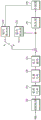
Fig. 5 illustrates a process of intra-predicting a current block based on a matrix as an embodiment of the present invention.
Referring to fig. 5, an intra prediction mode for intra prediction of a current block may be determined (S500).
The encoding/decoding apparatus may determine an intra prediction mode when performing intra prediction of the current block. The current block may be a coding block (CU), a prediction block (PU), a transform block (TU), or any one of these blocks.
(embodiment 1) the intra prediction mode may be determined based on information of a transfer signal. The information may specify any one of N intra prediction modes predefined in the encoding/decoding apparatus. The predefined intra prediction mode represents a natural number (e.g., 67, 35, 11) that can utilize all intra prediction modes of the current block, N can be less than or equal to 67, and greater than or equal to 11. In addition, the value of N may be determined based on the size of the current block. For example, when the current block is smaller than 8×8, N is determined to be 35, otherwise, N may be determined to be either 19 or 11.
(embodiment 2) the intra prediction mode may also be determined by a default mode or index previously agreed in the encoding/decoding apparatus. The default mode may be at least one of Planar mode (index 0, DC mode (index 1), horizontal mode (index 18), vertical mode (index 50), diagonal mode (index 2, 34, 66), wherein an index corresponds to a case where the predefined intra prediction modes are 67, and each mode may be divided into different indexes according to the value of N.
(embodiment 3) the intra prediction mode may be variably determined based on encoding information. The encoded information may include not only information encoded in the encoding device and transmitted to the signal, but also information derived based on information transmitted to the signal in the decoding device. The encoding information may be information about at least one of the current block or the neighboring block. The neighboring blocks include spatial and/or temporal neighboring blocks of the current block, and the spatial neighboring blocks may represent blocks neighboring at least one of a left side, an upper layer, an upper left layer, a lower left layer, or an upper right layer of the current block.
The encoded information may include: block size/shape, availability of blocks, partition type, number of partitions, component type, prediction mode, information on intra prediction mode, inter mode, motion information, transform type, transform skip mode, information on non-zero residual coefficients, scan order, color format, loop filter information, etc. The block size may be represented by any one of width or height, minimum/maximum value of width and height, sum of width and height, number of samples belonging to a block, and the like. The availability of the block may be judged by considering a block position, a range of parallel processing areas, a decoding order, and the like. The prediction mode may represent information indicating an intra mode or an inter mode. The information about the intra prediction mode may include: information about whether the intra prediction mode is a non-directional mode, whether the intra prediction mode is a vertical/horizontal mode, the directionality of the intra prediction mode, the number of intra prediction modes predefined in the encoding/decoding apparatus, and the like. The inter mode may represent information indicating a merge/skip mode, an AMVP mode, or a current picture reference mode. The current image reference mode represents a method of predicting a current block using a reconstructed region of a current image. The current image may be an image to which the current block belongs. The current picture may be added to a reference picture list for inter prediction, and the current picture may be arranged after a short-term (short-term) reference picture or a long-term (long-term) reference picture in the reference picture list. The motion information may include: prediction direction flags, motion vectors, reference picture indices, etc.
(embodiment 4) the intra prediction mode may also be derived based on an MPM list and an MPM index. The MPM list includes a plurality of MPMs, and the MPMs may be determined based on intra prediction modes of spatial/temporal neighboring blocks of the current block. The number of MPMs is x, which may be an integer of 3, 4, 5, 6, or more.
For example, the MPM list may include at least one of intra prediction modes mode a, (mode a-n), (mode a+n) or default modes of neighboring blocks. The value of n may be an integer of 1, 2, 3, 4 or more. The neighboring blocks may represent blocks neighboring the left and/or upper layers of the current block. The default mode may be at least one of Planar mode, DC mode, or a predetermined directionality mode. The predetermined directivity pattern may include at least one of a horizontal pattern (mode V), a vertical pattern (mode H), (mode V-k), (mode v+k), (mode H-k), or (mode h+k).
The MPM index may specify the same MPM as the intra prediction mode of the current block among MPMs of the MPM list. That is, the MPM specified by the MPM index may be set as the intra prediction mode of the current block.
The intra prediction mode of the current block may be selectively determined using any one of the foregoing embodiments 1 to 4, and may be determined based on at least 2 combinations of embodiments 1 to 4. A predetermined flag may be used for the selection, in which case the flag may be encoded by the encoding means and the signal transmitted.
Referring to fig. 5, a reference sample for intra prediction of a current block may be determined (S510).
The reference samples may be derived from neighboring regions of the current block. The neighboring area of the current block may include at least one of a left side, a right side, an upper layer, a lower left layer, an upper left layer, a lower right layer, or an upper right layer of the current block.
The adjacent region may comprise one or more sample lines. Specifically, the number of sample lines belonging to adjacent regions is k, where k may be 1, 2, 3, 4, or may be a natural number greater than these. The k value may be a fixed value predetermined in the encoding/decoding apparatus, or may be variably determined based on the foregoing encoded information. For example, when the current block is a first size (e.g., 4×4, 4×8, 8×4), the neighboring area may be configured as 1 sample line, and when the current block is a second size (e.g., 8×8, 16×16, etc.), the neighboring area may be configured as 2 sample lines. The sample line may be determined in a vertical direction or a horizontal direction according to the positions of the adjacent regions. And, the sample line may be in contact with the current block or may be separated from the current block by a predetermined distance in a vertical and/or horizontal direction.
The plurality of sample lines may exist continuously in the vertical and/or horizontal directions with reference to the current block, or may be separated from each other by a predetermined distance. As one embodiment, when there are 2 sample lines at the upper layer of the current block, from the sample line at the lowest layer among the 2 lines to the upward direction, they are named as the first and second sample lines, respectively. At this time, the first sample line and the second sample line may be in contact with each other or separated from each other by a predetermined distance. Wherein the predetermined distance may be represented by i line lengths (i.e., widths or heights). Where i may be a natural number of 0, 1, 2, 3 or more. As one embodiment, when there are 3 sample lines at the upper layer of the current block, from the sample line at the lowest layer among the plurality of sample lines to the upward direction, they are named as the first, second, and third sample lines, respectively. At this time, the first sample line may be in contact with the second sample line, and the second sample line may be in contact with the third sample line. Alternatively, the first to third sample lines may be distant from the aforementioned predetermined distance. At this time, the interval (d 1) between the first and second sample lines may have the same interval as the interval (d 2) between the second and third sample lines. Alternatively, d1 may be set to be larger than d2, and conversely, d1 may be set to be smaller than d2. As one embodiment, when there are more than 4 sample lines at the upper layer of the current block, the 4 sample lines may be determined in the same way as in the case of the 3 sample lines. In addition, the present embodiment can be applied not only to the sample line located at the upper layer but also to the sample line located at the left side, and a detailed description thereof will be omitted here.
The reference samples may be derived by using all or part of the samples belonging to adjacent regions.
(embodiment 1) some samples of the adjacent areas may be samples at positions previously agreed in the encoding/decoding apparatus. The pre-agreed locations may include: at least one of the leftmost, rightmost, or middle samples of the upper layer sample line. The pre-agreed locations may include: at least one of the uppermost sample, the lowermost sample, or the intermediate sample of the left sample line. Alternatively, the pre-agreed locations may include: at least one of the odd samples of the upper layer and/or left sample line, or at least one of the odd samples. Alternatively, the predetermined positions may include: samples having x coordinates of multiples of j in samples of an upper layer sample line or samples having y coordinates of multiples of j in samples of a left side sample line. Where j may be a natural number of 2, 3, 4, or greater.
(embodiment 2) some samples of the neighboring area may also be variably determined based on the encoded information. Wherein the encoded information is as previously described, and a detailed description thereof is omitted herein.
Either of the embodiments 1 or 2 may be selectively utilized, or some samples may be specified based on a combination of embodiments 1 and 2. At this time, as described above, the intervals between some samples may be set identically, but are not limited thereto, and the intervals between some samples may be set differently.
The number of some samples may be 1, 2, 3, 4 or more predefined in the encoding/decoding device. In addition, the number of some samples may be differently defined for the left neighboring region and the upper neighboring region of the current block, respectively. For example, when the width of the current block is greater than the height, the number of some samples (numSamA) belonging to the upper adjacent region may be greater than the number of some samples (numSamL) belonging to the left adjacent region. Conversely, when the width of the current block is less than the height, numSamA may be less than numSamL. Alternatively, the number of samples may be variably determined based on the foregoing encoded information.
The samples of the neighboring region may be prediction samples or reconstructed samples. The prediction samples may be obtained by intra prediction or inter prediction. The reconstructed samples may be reconstructed samples before the loop filter is applied, or reconstructed samples after the loop filter is applied.
Alternatively, the reference samples may be derived directly from samples of the neighboring region (CASE 1), or may be derived by downsampling samples of the neighboring region (CASE 2). Either of the CASE 1 and CASE 2 may be selectively utilized. The selection may be based on the aforementioned encoded information. For example, when the size of the current block is less than a predetermined threshold, reference samples may be derived based on CASE 1, otherwise, reference samples may be derived based on CASE 2. Wherein the size may be represented by any one of the width, the height, the maximum/minimum value of the width and the height, the ratio of the width to the height, or the product of the width and the height of the current block. As an example, when the current block is less than 8×8, the reference samples may be derived from samples of the neighboring region, otherwise, the reference samples may be derived from downsampling samples of the neighboring region. For the downsampling method, further understanding is made by referring to fig. 6 and 7.
Referring to fig. 5, a matrix for matrix-based intra prediction may be determined (S520).
The matrix may be determined based on at least one of the intra prediction mode determined in step S500 or the size of the current block. Alternatively, the matrix may be determined with restriction to consider only the intra prediction mode of the current block, or may be determined with restriction to consider only the size of the current block. The size may be represented by any one of a width or a height, a minimum/maximum value of the width and the height, a sum of the width and the height, the number of samples belonging to the current block, and the like. However, not limited thereto, the matrix may be determined further considering coding information about the current block. Wherein the encoded information is as previously described, and a detailed description thereof is omitted herein.
Specifically, the matrices previously agreed in the encoding/decoding apparatus may be divided into a plurality of matrix groups. The plurality of matrix groups may be configured by a first matrix group, a second matrix group, …, an mth matrix group. Wherein m may be a natural number of 2, 3, 4, 5 or more. Based on the size of the current block, the current block may selectively utilize any one of a plurality of matrix groups. For example, a first matrix group may be utilized when the size of the current block is 4×4, a second matrix group may be utilized when the sizes of the current block are 8×4, 4×8, and 8×8, and a third matrix group may be utilized in other cases. The matrix set selected based on the size of the current block may include one or more matrix candidates. Any one of a plurality of matrix candidates may be determined by a matrix of the current block. The determination may be made based on coding information (e.g.) of the current block.
The number of pre-agreed matrices may be the same as the number of pre-defined intra prediction modes described above. In addition, the number of pre-agreed matrices may be smaller than the number of pre-defined intra prediction modes. At this time, one matrix may be matched with a plurality of intra prediction modes. For example, one matrix may be matched to 2 intra prediction modes. At this time, the number of the pre-agreed matrices may have a value 1/2 times the number of the predefined intra prediction modes. However, not limited thereto, the number of intra prediction modes matched with one matrix may be 3, 4, 5, 6, or more.
As one embodiment, the matching may be determined by considering directionality and/or symmetry of intra prediction modes.
The predefined intra prediction mode may include a directional mode having a predetermined angle. The directivity pattern may be divided into a first pattern group having horizontal directivity and a second pattern group having vertical directivity. Assuming a number of directivity patterns of 65, the first pattern group may be configured to belong to patterns between index 2 and index 34, and the second pattern group may be configured to belong to patterns between index 34 and index 66.
The encoding/decoding apparatus defines only a matrix for the first pattern group, and the second pattern group can also use the matrix defined for the first pattern group. Instead, the encoding/decoding apparatus defines only a matrix for the second pattern group, and the first pattern group may also utilize the matrix defined for the second pattern group. At this time, the number of matrices agreed in advance may have a value 1/2 times the number of predefined intra prediction modes. As an embodiment, when the mode group having symmetry is x, the number of the predetermined matrices may have a value 1/x times the number of the predefined intra prediction modes. Wherein x may be 3, 4 or more.
The symmetry may be based on intra prediction modes having an angle of-45 °, including symmetry of prediction angles between modes having vertical directivity and modes having horizontal directivity. Among them, the intra prediction mode having directionality has a prediction angle (PredAngle) according to each directionality. Wherein the mode having vertical directivity may be based on an intra prediction mode having the angle of-45 °, including a mode having an angle of-45 ° < (PredAngle) +.45 ° in the x-axis direction from the mode and the mode. Wherein the mode having horizontal directivity may include, with reference to an intra-prediction mode in which the angle is-45 °, a mode having an angle of-45 ° < (PredAngle) +.45 ° in the y-axis direction from the mode other than the mode.
Referring to fig. 5, a current block may be predicted based on the reference samples and the matrix (S530).
When the reference samples are determined in step S510 and the matrix is determined in step S520, the encoding/decoding apparatus may predict the current block based on the reference samples and the matrix.
The predicting the current block may include: and a step of applying the matrix to the reference samples to obtain prediction samples (hereinafter, referred to as first prediction samples) of the DS block. The DS block may represent a current block or may represent a current block that has been downsampled. That is, the DS block may also have the same size as the current block, and the size of the current block may also have a size of 1/2, 1/4, 1/8, or 1/16 (of at least one of width or height). For example, when the current block is a 4×4, 4×8, or 8×4 block, the DS block may be a 4×4 block. Alternatively, when the current block is not an 8×8, 8×16, or 16×8 block, the DS block may be a 4×4 or 8×8 block. Alternatively, when the current block is greater than or equal to 16×16, the DS block may be an 8×8 or 16×16 block. However, the DS blocks are not limited to square blocks, but may be non-square blocks. Alternatively, the DS blocks may be limited to square blocks. Wherein the adapting of the matrix may comprise multiplying the reference samples by a weighting value obtained from the matrix.
The step of obtaining the first prediction sample may include: at least one of the step of adding an offset value or the step of filtering.
The step of obtaining the first prediction sample may further include: and rearranging the first prediction samples. The rearrangement may be performed only in a case where a plurality of intra prediction modes are matched in one matrix.
Alternatively, the rearrangement may be performed when the intra prediction mode of the current block belongs to the first mode group having horizontal directivity. For example, when the intra prediction mode of the current block belongs to the first mode group having the horizontal directivity, the rearrangement of the first prediction samples for the DS block is performed, and when the intra prediction mode of the current block belongs to the second mode group having the vertical directivity, the rearrangement of the first prediction samples for the DS block may not be performed.
In contrast, the rearrangement may be performed when the intra prediction mode of the current block belongs to the first mode group having vertical directivity. For example, when the intra prediction mode of the current block belongs to the first mode group having the horizontal directivity, rearrangement of the first prediction samples for the DS block is not performed, and when the intra prediction mode of the current block belongs to the second mode group having the vertical directivity, rearrangement of the first prediction samples for the DS block may be performed.
The rearrangement may be performed as in the following equation 1. Where x may represent x-axis coordinate values and y may represent y-axis coordinate values. That is, the rearrangement may represent a process of assigning the first prediction sample of the (x, y) coordinates to the (y, x) coordinates.
[ formula 1]
First prediction sample [ x ] [ y ] =first prediction sample [ y ] [ x ]
Alternatively, the rearrangement according to the present invention may also represent a process in which the DS block composed of the first prediction samples is rotated by a predetermined angle. The predetermined angle may be 90 degrees or 180 degrees in the clockwise direction or 90 degrees or 180 degrees in the counterclockwise direction.
The step of predicting the current block may further include: and upsampling the current block based on at least one of the neighboring reconstructed samples or the first prediction samples to obtain a second prediction sample.
In the upsampling process, it may be determined whether to perform at least one of the upsampling or the upsampling method based on coding information of the current block. For example, it may be determined whether to perform at least one of the upsampling or the upsampling method based on the size of the DS block made up of the first prediction samples and the size of the current block. The block size may be represented by any one of width or height, minimum/maximum value of width and height, sum of width and height, number of samples belonging to a block, and the like.
It may be determined whether to perform the upsampling only when the size of the DS block composed of the first prediction samples is smaller than the size of the current block.
The up-sampling method may include: allocating the first prediction samples into predetermined positions within the current block using a ratio of a size of a DS block composed of the first prediction samples to a size of the current block; and interpolating a remaining region within the current block. The remaining region may represent a region other than a region dividing the first prediction sample in the current block. The division for the first prediction samples and the interpolation method for the remaining region will be described in detail with reference to fig. 8 to 10.
Fig. 6 illustrates a method of down-sampling adjacent regions to determine a reference sample as an embodiment to which the present invention is applied.
Referring to fig. 6, fig. 6 (a) shows a case where a neighboring region for intra prediction is located at the left side of the current block and at the upper layer. In addition, as one embodiment, a sample line located on the left side of the current block is in contact with the current block and is constituted of 1 sample line in the vertical direction. The sample line located at the upper layer of the current block is in contact with the current block and is composed of 1 sample line in the horizontal direction.
The reference samples may include downsampled regions formed by downsampling neighboring regions of the current block.
The downsampled region may be derived from an average, a maximum, a minimum, a mode, or a filtered value of all or some samples belonging to the neighboring region.
When derived from the average value, the downsampled region may be formed by a method that assigns an average value of different N samples into samples of the downsampled region.
The different N samples may be consecutively arranged samples, or may be spaced apart at intervals. The certain interval is one or more sample-sized intervals. When the interval is plural, the plural intervals may be uniform or nonuniform. (wherein N is greater than 2 and less than the total number of samples belonging to the adjacent region.) additionally, the combination of the different N samples is referred to as a sample group. At this time, the first sample group may overlap with the second sample group, or may not overlap.
As an example, fig. 6 shows that N is 2,2 sample groups do not overlap each other, and the average value of 2 samples belonging to each sample group is respectively allocated to 1 sample in the downsampling region to perform downsampling.
Alternatively, consecutive 3 samples (S1, S2, S3) may constitute the first sample group, and an average value of 3 samples belonging to the first sample group may be allocated to the sample (DS 1) of the downsampling region. The consecutive 3 samples (S2, S3, S4) may constitute a second sample group, and an average value of 3 samples belonging to the second sample group may be allocated to the sample (DS 2) of the downsampling area.
Alternatively, after the minimum value or the maximum value among the 2 samples (S1, S2) belonging to the first sample group is determined, it may be allocated to the sample (DS 1) of the downsampling region. Likewise, after the minimum value or the maximum value among the 2 samples (S3, S4) belonging to the second sample group is determined, it may be allocated to the sample (DS 2) of the downsampling region. The same can be used also in the case where the first/second sample group is composed of 3 samples.
Alternatively, in the upper layer neighboring region, samples at a predefined position among the plurality of samples belonging to the first sample group may be allocated into samples (DS 1) of the downsampling region, and samples at a predefined position among the plurality of samples belonging to the second sample group may be allocated into samples (DS 2) of the downsampling region. The predefined position may represent a fixed position pre-agreed in the encoding/decoding apparatus, and may be any one of leftmost, rightmost, or intermediate positions, as an example. In the left adjacent region, samples at predefined positions among the plurality of samples belonging to the respective sample groups may also be respectively allocated to the samples of the downsampling region. At this time, the predefined position may be any one of the uppermost layer, the lowermost layer, or the intermediate position.
Fig. 7 shows a downsampling method based on a weighted average as an embodiment to which the present invention is applied.
In this embodiment, the average value may be calculated by the following formula (hereinafter, referred to as a first average expression):
samples and/or number of samples belonging to a sample group;
or by the following formula (hereinafter, referred to as a second average expression):
sum (weight x samples belonging to the group of samples)/number of samples.
Fig. 7 (a) shows a case where the aforementioned sample group is constituted of 3 samples. At this time, the weighting value applied to 3 samples may be determined as 1:2: 1. As shown in fig. 7 (b), when the sample group is composed of 5 samples, the weight value may be determined as 1:1:4:1: 1. As shown in fig. 7 (c), when the sample group is made up of 6 samples, the weight value may be determined as 1 in the Z direction with the upper layer on the left side as the starting point: 2:1:2:2:1 or 1:2:2:1:2: 1. In addition, although (a) and (c) of fig. 7 show the weighting values applied to the upper layer neighboring region, the same may be applied to the left side neighboring region.
The average value may also include: and applying a predetermined operation to a result value derived from a plurality of average values calculated by the first average expression or the second average expression. Wherein the predetermined operation may be the aforementioned first average expression or second average expression. For example, if 3 samples (i.e., first to third samples) belong to a sample group, an average value (first value) between the first sample and the second sample, and an average value (second value) between the second sample and the third sample may be calculated, respectively. The average value may be derived from an average value between the calculated first value and the second value.
The aforementioned downsampling method may be applied only to the upper adjacent region, and conversely, may be applied only to the left adjacent region. Alternatively, the down-sampling method (hereinafter, referred to as a first method) according to fig. 6 may be applied to either one of the upper layer or the left adjacent region, and the down-sampling method (hereinafter, referred to as a second method) according to fig. 7 may be applied to the other one of the upper layer or the left adjacent region.
In addition, at least one of the first method or the second method may be selectively utilized in consideration of the size/shape of the current block. For example, the first method may be applied to an upper adjacent region of the current block when the width of the current block is greater than a predetermined threshold, and otherwise, the second method may be applied. The height of the current block may also be downsampled in the same manner. Alternatively, when the current block is non-square, the first method may be applied to any one of the upper layer or the left neighboring region, and the second method may be applied to the other region. At this time, when the width of the current block is greater than the height, the first method may be applied to the upper adjacent region and the second method may be applied to the left adjacent region. Conversely, when the width of the current block is smaller than the height, the second method may be applied to the upper adjacent region and the first method may be applied to the left adjacent region. When the current block is square, the same downsampling method may be used in the upper layer and the left neighboring region, wherein the downsampling method may also be limited to the first method.
Fig. 8 illustrates a division of a first prediction sample and an interpolation method for the remaining region as an embodiment to which the present invention is applied.
Referring to fig. 8 (a), prediction samples of the DS block may be allocated into prediction samples at predetermined positions in the current block. Wherein the predetermined position may be determined by considering a size ratio between the current block and the DS block. For example, the correspondence of the prediction samples between the DS block and the current block may be defined as in the following equation 2.
[ formula 2]
First prediction sample curBLK [ (x+1) ×r-1] [ y+1) ×r-1] =first prediction sample dsBLK [ x ] [ y ]
Where r represents the size ratio between the current block and the DS block, and x and y are the x-axis and y-axis coordinates of the first prediction samples in each DS block, respectively. The first prediction sample curBLK may represent a position of the first prediction sample within the current block, and the first prediction sample dsBLK may represent a position of the first prediction sample within the DS block.
The interpolation, referring to (b) of fig. 8, may derive a sample (hereinafter, referred to as an interpolation target sample) in which the first prediction sample is not divided in the current block using at least one of the first prediction sample divided to the current block or reconstructed samples adjacent to the current block (hereinafter, referred to as an interpolation reference sample). In addition, the interpolation reference sample may further include a prediction sample generated by interpolation before the current interpolation object sample (i.e., the last interpolation object sample).
The positions and ranges of the reconstructed samples adjacent to the current block are the same as those of the aforementioned reference samples, so a detailed description thereof will be omitted herein.
The interpolation reference sample may be composed of a plurality of first prediction samples, or may be composed of at least one first prediction sample and at least one reconstructed neighboring sample, according to the position of the interpolation object sample. The reconstructed neighboring samples may selectively use any one of the samples having the same x-coordinate or y-coordinate as the interpolation object sample, or may use a plurality of samples of at least one of the x-coordinate or y-coordinate and the interpolation object sample. The selection may be based on the location of the interpolation object samples. For example, if the interpolation object sample has the same x-coordinate as the first prediction sample, the reconstructed neighboring sample may include only samples having the same x-coordinate as the interpolation object sample. Conversely, if the interpolation object sample has the same y-coordinate as the first prediction sample, the reconstructed neighboring sample may include only samples having the same y-coordinate as the interpolation object sample. Alternatively, the reconstructed adjacent samples may also include a plurality of samples located on the same horizontal and vertical lines as the interpolation object samples.
The interpolation object sample may be derived from representative values of a plurality of interpolation reference samples, wherein the representative values may include any one of an average value, a minimum value, a maximum value, a mode, or an intermediate value.
The average value may be calculated by the following formula (hereinafter, referred to as a first average expression):
difference reference sample sum/difference reference sample number;
or may be calculated by the following formula (hereinafter, referred to as a second average expression):
sum (weight value x difference reference sample)/difference reference sample number.
The weight value according to the second average expression may be determined based on the relative/absolute distance between the interpolation object sample and the interpolation reference sample, which may be described in detail with reference to fig. 9.
Fig. 9 shows that weight values for distances are assigned in the interpolation step as an embodiment to which the present invention is applied.
The weighting value according to the present invention may include a weighting value determined based on a distance from the interpolation object sample to the interpolation reference sample. As an example, referring to fig. 9, if the first interpolation object sample 910 is interpolated, since the respective distance ratio from the first interpolation object sample 910 to the first interpolation reference sample 911 and the second interpolation reference sample 912 is 3:1, the weight ratio applicable to the first and second interpolated reference samples 911 and 911 may be 1:3. if the second interpolation object sample 920 is interpolated, since the ratio of the distances from the second interpolation object sample 920 to each of the first interpolation reference sample 921 and the second interpolation reference sample 922 is 1:1, the weight ratio applicable to the first and second interpolated reference samples 921, 922 may be 1:1.
In addition, the interpolation filter according to the present invention may have directivity. The directionality may include vertical, horizontal, z-type, diagonal, etc. directions.
The interpolation may be performed based on a predetermined order of preference. The priority order may be any one of a case (first order) where interpolation is performed in the vertical direction and then interpolation is performed in the horizontal direction and a case (second order) where interpolation is performed in the vertical direction and then interpolation is performed in the horizontal direction. Or interpolation may be performed in both the vertical direction and the horizontal direction (third order).
The current block may be interpolated using only any one of the aforementioned first to third orders, or may be interpolated using at least 2 combinations of the first to third orders. For interpolation sequences, please refer to fig. 10 for detailed understanding.
Fig. 10 shows a sequence of interpolation steps as an embodiment to which the present invention is applied.
Fig. 10 (a) is a diagram of the first sequence in fig. 9. Specifically, the vertical line to which the first prediction sample belongs may be interpolated first, and then the horizontal line may be interpolated based on the interpolated line and the interpolated reference sample on the left side of the current block.
Fig. 10 (b) is a second sequence with respect to fig. 9. Specifically, the horizontal line to which the first prediction sample belongs may be interpolated first, and then the vertical line may be interpolated based on the interpolated line and the interpolated reference sample at the upper layer of the current block.
Fig. 10 (c) is a third sequence with respect to fig. 9. First, the vertical and horizontal lines to which the first prediction samples belong may be interpolated. Then, interpolation is performed for the remaining samples not subjected to interpolation, at which time only the vertical line or the horizontal line may be interpolated, or both the vertical line and the horizontal line may be interpolated. If the vertical and horizontal lines are interpolated at the same time, one interpolation object sample may have a first interpolation value on the vertical line and a second interpolation value on the horizontal line at the same time. At this time, a representative value between the first interpolation value and the second interpolation value may be assigned to the interpolation object sample. Wherein the representative value may be derived from the average, minimum, maximum, mode, or median value.
The interpolation order may be an order previously agreed in the encoding/decoding apparatus, or may be selectively determined based on encoding information of the current block. Wherein the encoded information is as described previously, and thus a detailed description thereof is omitted.
The order may be determined based on block size. The block size may be represented by any one of width or height, minimum/maximum value of width and height, sum of width and height, number of samples belonging to a block, and the like.
For example, the first interpolation may be performed when the size of the current block is greater than a predetermined threshold, otherwise the second interpolation may be performed. Conversely, the second interpolation may be performed when the size of the current block is less than a predetermined threshold, otherwise the first interpolation may be performed. The threshold may be a natural number of 8, 16, 32 or more.
Claims (23)
1. A video signal processing method, wherein the video signal processing method is applied to a decoder, comprising:
determining an intra prediction mode of the current block;
determining reference samples for intra prediction of the current block;
determining a predetermined matrix based on the intra prediction mode; and
generating a prediction block by applying the matrix to the reference samples; wherein applying the matrix to the reference samples comprises multiplying the reference samples by a weight obtained from the matrix;
all or part of the prediction samples of the generated prediction block are transposed.
2. The method of video signal processing according to claim 1, wherein determining the reference samples comprises:
determining adjacent areas of the current block; and
downsampling the determined neighboring area.
3. The video signal processing method according to claim 2, wherein,
the adjacent regions are divided into a plurality of sample groups,
the sample set is made up of one or more samples,
a representative value of the set of samples is determined as the reference sample,
the representative value is any one of an average value, a minimum value, a maximum value, a mode, and an intermediate value.
4. The video signal processing method according to claim 1, wherein,
the matrix is determined by further considering coding information of the current block,
the encoding information includes a size and a shape of the current block.
5. The video signal processing method according to claim 4, wherein the method further comprises:
the current block is interpolated based on at least one of the predicted block or reconstructed samples adjacent to the current block.
6. A video signal processing method, wherein the video signal processing method is applied to an encoder, comprising:
determining an intra prediction mode of the current block;
determining reference samples for intra prediction of the current block;
determining a predetermined matrix based on the intra prediction mode; and
Generating a prediction block by applying the matrix to the reference samples; wherein applying the matrix to the reference samples comprises multiplying the reference samples by a weight obtained from the matrix;
all or part of the prediction samples of the generated prediction block are transposed.
7. The method of video signal processing according to claim 6, wherein determining the reference samples comprises:
determining adjacent areas of the current block; and
downsampling the determined neighboring area.
8. The method for processing a video signal as claimed in claim 7, wherein,
the adjacent regions are divided into a plurality of sample groups,
the sample set is made up of one or more samples,
a representative value of the set of samples is determined as the reference sample,
the representative value is any one of an average value, a minimum value, a maximum value, a mode, and an intermediate value.
9. The method for processing a video signal as claimed in claim 6, wherein,
the matrix is determined by further considering coding information of the current block,
the encoding information includes a size and a shape of the current block.
10. The video signal processing method according to claim 9, characterized in that the method further comprises:
The current block is interpolated based on at least one of the predicted block or reconstructed samples adjacent to the current block.
11. A decoder, the decoder comprising: a first determination unit and a first prediction unit,
the first determining unit is used for determining an intra-frame prediction mode of the current block; and determining reference samples for intra prediction of the current block; and determining a predetermined matrix based on the intra prediction mode;
the first prediction unit is configured to generate a prediction block by applying the matrix to the reference samples; wherein applying the matrix to the reference samples comprises multiplying the reference samples by a weight obtained from the matrix; all or part of the prediction samples of the generated prediction block are transposed.
12. The decoder of claim 11, wherein,
the first determining unit is specifically configured to determine an adjacent area of the current block; and downsampling the determined neighboring area.
13. The decoder of claim 12, wherein,
the adjacent regions are divided into a plurality of sample groups,
the sample set is made up of one or more samples,
A representative value of the set of samples is determined as the reference sample,
the representative value is any one of an average value, a minimum value, a maximum value, a mode, and an intermediate value.
14. The decoder of claim 11, wherein,
the first determining unit is further specifically configured to determine the matrix by further considering coding information of the current block, where the coding information includes a size and a shape of the current block.
15. The decoder of claim 11, wherein,
the first prediction unit is further specifically configured to interpolate the current block based on at least one of the prediction block or reconstructed samples adjacent to the current block.
16. A decoder comprising a first processor and a first memory storing instructions executable by the first processor, which when executed by the first processor, implement the method of any of claims 1-5.
17. An encoder, the encoder comprising: a second determination unit and a second prediction unit,
the second determining unit is used for determining an intra prediction mode of the current block; and determining reference samples for intra prediction of the current block; and determining a predetermined matrix based on the intra prediction mode;
The second prediction unit is configured to generate a prediction block by applying the matrix to the reference samples; wherein applying the matrix to the reference samples comprises multiplying the reference samples by a weight obtained from the matrix; all or part of the prediction samples of the generated prediction block are transposed.
18. The encoder of claim 17, wherein the encoder further comprises a decoder,
the second determining unit is specifically configured to determine an adjacent area of the current block; and downsampling the determined neighboring area.
19. The encoder of claim 18, wherein the encoder further comprises a decoder,
the adjacent regions are divided into a plurality of sample groups,
the sample set is made up of one or more samples,
a representative value of the set of samples is determined as the reference sample,
the representative value is any one of an average value, a minimum value, a maximum value, a mode, and an intermediate value.
20. The encoder of claim 17, wherein the encoder further comprises a decoder,
the second determining unit is further specifically configured to determine the matrix by further considering coding information of the current block, where the coding information includes a size and a shape of the current block.
21. The encoder of claim 17, wherein the encoder further comprises a decoder,
the second prediction unit is further configured to interpolate the current block based on at least one of the prediction block or reconstructed samples adjacent to the current block.
22. An encoder comprising a second processor and a second memory storing instructions executable by the second processor, which when executed by the second processor, implement the method of any of claims 6-10.
23. A computer storage medium storing a computer program which when executed by a first processor performs the method of any one of claims 1-5 or when executed by a second processor performs the method of any one of claims 6-10.
Priority Applications (1)
| Application Number | Priority Date | Filing Date | Title |
|---|---|---|---|
| CN202110462138.3A CN113225557B (en) | 2018-09-07 | 2019-09-06 | Image encoding/decoding method and apparatus using intra prediction |
Applications Claiming Priority (5)
| Application Number | Priority Date | Filing Date | Title |
|---|---|---|---|
| KR20180107255 | 2018-09-07 | ||
| KR10-2018-0107255 | 2018-09-07 | ||
| PCT/KR2019/011554 WO2020050684A1 (en) | 2018-09-07 | 2019-09-06 | Image encoding/decoding method and device using intra prediction |
| CN202110462138.3A CN113225557B (en) | 2018-09-07 | 2019-09-06 | Image encoding/decoding method and apparatus using intra prediction |
| CN201980056309.3A CN112806001A (en) | 2018-09-07 | 2019-09-06 | Image encoding/decoding method and apparatus using intra prediction |
Related Parent Applications (1)
| Application Number | Title | Priority Date | Filing Date |
|---|---|---|---|
| CN201980056309.3A Division CN112806001A (en) | 2018-09-07 | 2019-09-06 | Image encoding/decoding method and apparatus using intra prediction |
Publications (2)
| Publication Number | Publication Date |
|---|---|
| CN113225557A CN113225557A (en) | 2021-08-06 |
| CN113225557B true CN113225557B (en) | 2023-06-20 |
Family
ID=69722959
Family Applications (4)
| Application Number | Title | Priority Date | Filing Date |
|---|---|---|---|
| CN202310426208.9A Pending CN116405679A (en) | 2018-09-07 | 2019-09-06 | Image encoding/decoding method and apparatus using intra prediction |
| CN202310429492.5A Pending CN116389742A (en) | 2018-09-07 | 2019-09-06 | Image encoding/decoding method and apparatus using intra prediction |
| CN202110462138.3A Active CN113225557B (en) | 2018-09-07 | 2019-09-06 | Image encoding/decoding method and apparatus using intra prediction |
| CN201980056309.3A Pending CN112806001A (en) | 2018-09-07 | 2019-09-06 | Image encoding/decoding method and apparatus using intra prediction |
Family Applications Before (2)
| Application Number | Title | Priority Date | Filing Date |
|---|---|---|---|
| CN202310426208.9A Pending CN116405679A (en) | 2018-09-07 | 2019-09-06 | Image encoding/decoding method and apparatus using intra prediction |
| CN202310429492.5A Pending CN116389742A (en) | 2018-09-07 | 2019-09-06 | Image encoding/decoding method and apparatus using intra prediction |
Family Applications After (1)
| Application Number | Title | Priority Date | Filing Date |
|---|---|---|---|
| CN201980056309.3A Pending CN112806001A (en) | 2018-09-07 | 2019-09-06 | Image encoding/decoding method and apparatus using intra prediction |
Country Status (15)
| Country | Link |
|---|---|
| US (5) | US11477439B2 (en) |
| EP (1) | EP3833021A4 (en) |
| JP (3) | JP7448526B2 (en) |
| KR (1) | KR20200028856A (en) |
| CN (4) | CN116405679A (en) |
| AU (1) | AU2019336038A1 (en) |
| BR (1) | BR112021004024A2 (en) |
| CA (1) | CA3111982C (en) |
| CL (1) | CL2021000527A1 (en) |
| IL (1) | IL281221A (en) |
| MX (1) | MX2021002608A (en) |
| PH (1) | PH12021550480A1 (en) |
| SG (1) | SG11202102238SA (en) |
| WO (1) | WO2020050684A1 (en) |
| ZA (1) | ZA202101569B (en) |
Families Citing this family (16)
| Publication number | Priority date | Publication date | Assignee | Title |
|---|---|---|---|---|
| SG11202102857QA (en) | 2018-09-21 | 2021-04-29 | Guangdong Oppo Mobile Telecommunications Corp Ltd | Method for encoding/decoding image signal and apparatus therefor |
| CA3113054A1 (en) | 2018-09-21 | 2020-03-26 | Guangdong Oppo Mobile Telecommunications Corp., Ltd. | Image signal encoding/decoding method and device therefor |
| EP3893509A4 (en) | 2018-12-07 | 2022-10-26 | Samsung Electronics Co., Ltd. | Video decoding method and device, and video encoding method and device |
| AU2018454766A1 (en) | 2018-12-25 | 2021-04-08 | Guangdong Oppo Mobile Telecommunications Corp., Ltd. | Decoding prediction method and apparatus, and computer storage medium |
| SG11202110936PA (en) * | 2019-04-12 | 2021-11-29 | Beijing Bytedance Network Technology Co Ltd | Chroma coding mode determination based on matrix-based intra prediction |
| JP7403555B2 (en) | 2019-04-16 | 2023-12-22 | 北京字節跳動網絡技術有限公司 | Matrix derivation in intracoding mode |
| CN113812150B (en) | 2019-05-01 | 2023-11-28 | 北京字节跳动网络技术有限公司 | Matrix-based intra prediction using filtering |
| CN117097912A (en) | 2019-05-01 | 2023-11-21 | 北京字节跳动网络技术有限公司 | Matrix-based intra-prediction context coding |
| BR112021022868A2 (en) | 2019-05-22 | 2022-01-04 | Beijing Bytedance Network Tech Co Ltd | Video processing method, apparatus for processing video data and computer readable non-transient storage and recording media |
| CN113924775B (en) | 2019-05-31 | 2023-11-14 | 北京字节跳动网络技术有限公司 | Restricted upsampling in matrix-based intra prediction |
| EP3958571A4 (en) * | 2019-06-03 | 2022-07-27 | LG Electronics Inc. | Matrix-based intra prediction device and method |
| WO2020244610A1 (en) | 2019-06-05 | 2020-12-10 | Beijing Bytedance Network Technology Co., Ltd. | Context determination for matrix-based intra prediction |
| EP4042689A4 (en) | 2019-10-28 | 2023-06-07 | Beijing Bytedance Network Technology Co., Ltd. | Syntax signaling and parsing based on colour component |
| WO2022186620A1 (en) * | 2021-03-04 | 2022-09-09 | 현대자동차주식회사 | Video coding method and apparatus for improving prediction signals of intra prediction |
| WO2023039859A1 (en) * | 2021-09-17 | 2023-03-23 | Oppo广东移动通信有限公司 | Video encoding method, video decoding method, and device, system and storage medium |
| WO2023204624A1 (en) * | 2022-04-20 | 2023-10-26 | 엘지전자 주식회사 | Method and device for encoding/decoding image on basis of convolutional cross-component model (cccm) prediction, and recording medium for storing bitstream |
Citations (2)
| Publication number | Priority date | Publication date | Assignee | Title |
|---|---|---|---|---|
| CN108353185A (en) * | 2015-08-28 | 2018-07-31 | 株式会社Kt | Method and apparatus for handling vision signal |
| CN108370441A (en) * | 2015-11-12 | 2018-08-03 | Lg 电子株式会社 | Method and apparatus in image compiling system for intra prediction caused by coefficient |
Family Cites Families (28)
| Publication number | Priority date | Publication date | Assignee | Title |
|---|---|---|---|---|
| KR20080082143A (en) * | 2007-03-07 | 2008-09-11 | 삼성전자주식회사 | An image encoding/decoding method and apparatus |
| US8705619B2 (en) * | 2010-04-09 | 2014-04-22 | Sony Corporation | Directional discrete wavelet transform (DDWT) for video compression applications |
| WO2011145862A2 (en) * | 2010-05-17 | 2011-11-24 | Lg Electronics Inc. | New intra prediction modes |
| US9258573B2 (en) | 2010-12-07 | 2016-02-09 | Panasonic Intellectual Property Corporation Of America | Pixel adaptive intra smoothing |
| US10992958B2 (en) * | 2010-12-29 | 2021-04-27 | Qualcomm Incorporated | Video coding using mapped transforms and scanning modes |
| US20120218432A1 (en) | 2011-02-28 | 2012-08-30 | Sony Corporation | Recursive adaptive intra smoothing for video coding |
| US20130336398A1 (en) * | 2011-03-10 | 2013-12-19 | Electronics And Telecommunications Research Institute | Method and device for intra-prediction |
| US8861593B2 (en) * | 2011-03-15 | 2014-10-14 | Sony Corporation | Context adaptation within video coding modules |
| KR20120140181A (en) * | 2011-06-20 | 2012-12-28 | 한국전자통신연구원 | Method and apparatus for encoding and decoding using filtering for prediction block boundary |
| KR101654673B1 (en) * | 2011-06-28 | 2016-09-22 | 삼성전자주식회사 | Method and apparatus for video intra prediction encoding, and method and apparatus for video intra prediction decoding |
| JP6242793B2 (en) | 2011-09-15 | 2017-12-06 | ヴィド スケール インコーポレイテッド | System and method for spatial prediction |
| KR20130037161A (en) * | 2011-10-05 | 2013-04-15 | 한국전자통신연구원 | Method and apparatus of improved inter-layer motion prediction for scalable video coding |
| CN105338348B (en) * | 2011-10-24 | 2018-11-13 | 英孚布瑞智有限私人贸易公司 | Method and apparatus for image decoding |
| WO2015182342A1 (en) * | 2014-05-26 | 2015-12-03 | シャープ株式会社 | Image decoding device, and image encoding device |
| CN108141609A (en) | 2015-10-21 | 2018-06-08 | 夏普株式会社 | Prognostic chart picture generating means, picture decoding apparatus and picture coding device |
| KR20180136555A (en) * | 2016-06-03 | 2018-12-24 | 엘지전자 주식회사 | Intra prediction method and apparatus in video coding system |
| US10484712B2 (en) * | 2016-06-08 | 2019-11-19 | Qualcomm Incorporated | Implicit coding of reference line index used in intra prediction |
| CN116866613A (en) | 2016-06-22 | 2023-10-10 | Lx 半导体科技有限公司 | Image encoding/decoding method and image data transmission method |
| ES2699691R1 (en) | 2016-06-24 | 2019-04-05 | Kt Corp | Method and apparatus for processing video signals |
| CN113873240A (en) * | 2016-06-24 | 2021-12-31 | 株式会社Kt | Method and apparatus for processing video signal |
| US10477240B2 (en) * | 2016-12-19 | 2019-11-12 | Qualcomm Incorporated | Linear model prediction mode with sample accessing for video coding |
| CA3065922A1 (en) * | 2017-09-08 | 2019-03-14 | Kt Corporation | Method and device for processing video signal |
| US11350107B2 (en) * | 2017-11-16 | 2022-05-31 | Electronics And Telecommunications Research Institute | Image encoding/decoding method and device, and recording medium storing bitstream |
| CA3088026C (en) * | 2017-12-15 | 2023-10-03 | Lg Electronics Inc. | Image coding method on basis of transformation and device therefor |
| EP4307676A3 (en) * | 2017-12-21 | 2024-03-13 | LG Electronics Inc. | Method for coding image on basis of selective transform and device therefor |
| US11533508B2 (en) * | 2018-06-08 | 2022-12-20 | Kt Corporation | Method and apparatus for encoding/decoding residual data based on a plurality of transformations |
| BR112020025916A2 (en) | 2018-06-30 | 2021-03-16 | Guangdong Oppo Mobile Telecommunications Corp., Ltd. | METHOD FOR DECODING A VIDEO SIGNAL |
| US10404980B1 (en) * | 2018-07-10 | 2019-09-03 | Tencent America LLC | Intra prediction with wide angle mode in video coding |
-
2019
- 2019-09-05 KR KR1020190110217A patent/KR20200028856A/en active Search and Examination
- 2019-09-06 CN CN202310426208.9A patent/CN116405679A/en active Pending
- 2019-09-06 WO PCT/KR2019/011554 patent/WO2020050684A1/en unknown
- 2019-09-06 EP EP19858139.9A patent/EP3833021A4/en active Pending
- 2019-09-06 SG SG11202102238SA patent/SG11202102238SA/en unknown
- 2019-09-06 CN CN202310429492.5A patent/CN116389742A/en active Pending
- 2019-09-06 JP JP2021512701A patent/JP7448526B2/en active Active
- 2019-09-06 CA CA3111982A patent/CA3111982C/en active Active
- 2019-09-06 BR BR112021004024-2A patent/BR112021004024A2/en unknown
- 2019-09-06 MX MX2021002608A patent/MX2021002608A/en unknown
- 2019-09-06 CN CN202110462138.3A patent/CN113225557B/en active Active
- 2019-09-06 CN CN201980056309.3A patent/CN112806001A/en active Pending
- 2019-09-06 AU AU2019336038A patent/AU2019336038A1/en active Pending
-
2021
- 2021-03-03 IL IL281221A patent/IL281221A/en unknown
- 2021-03-03 CL CL2021000527A patent/CL2021000527A1/en unknown
- 2021-03-04 US US17/192,733 patent/US11477439B2/en active Active
- 2021-03-05 PH PH12021550480A patent/PH12021550480A1/en unknown
- 2021-03-08 ZA ZA2021/01569A patent/ZA202101569B/en unknown
-
2022
- 2022-09-15 US US17/932,585 patent/US20230026401A1/en active Pending
- 2022-09-15 US US17/932,627 patent/US20230024256A1/en active Pending
- 2022-09-15 US US17/932,636 patent/US20230026704A1/en active Pending
- 2022-09-15 US US17/932,632 patent/US20230024482A1/en active Pending
-
2024
- 2024-02-29 JP JP2024029883A patent/JP2024059905A/en active Pending
- 2024-02-29 JP JP2024029923A patent/JP2024059906A/en active Pending
Patent Citations (2)
| Publication number | Priority date | Publication date | Assignee | Title |
|---|---|---|---|---|
| CN108353185A (en) * | 2015-08-28 | 2018-07-31 | 株式会社Kt | Method and apparatus for handling vision signal |
| CN108370441A (en) * | 2015-11-12 | 2018-08-03 | Lg 电子株式会社 | Method and apparatus in image compiling system for intra prediction caused by coefficient |
Non-Patent Citations (1)
| Title |
|---|
| Description of SDR, HDR, and 360° video coding technology proposal by Fraunhofer HHI;M. Albrecht 等;《Joint Video Experts Team (JVET) of ITU-T SG 16 WP 3 and ISO/IEC JTC 1/SC 29/WG 11》;20180402;第1-49页 * |
Also Published As
| Publication number | Publication date |
|---|---|
| CN113225557A (en) | 2021-08-06 |
| SG11202102238SA (en) | 2021-04-29 |
| JP2022501881A (en) | 2022-01-06 |
| JP2024059905A (en) | 2024-05-01 |
| IL281221A (en) | 2021-04-29 |
| CL2021000527A1 (en) | 2021-08-20 |
| US20210195176A1 (en) | 2021-06-24 |
| CA3111982C (en) | 2024-02-27 |
| WO2020050684A1 (en) | 2020-03-12 |
| EP3833021A4 (en) | 2021-10-06 |
| CN112806001A (en) | 2021-05-14 |
| US20230024482A1 (en) | 2023-01-26 |
| JP2024059906A (en) | 2024-05-01 |
| CN116389742A (en) | 2023-07-04 |
| US20230026401A1 (en) | 2023-01-26 |
| US20230026704A1 (en) | 2023-01-26 |
| US11477439B2 (en) | 2022-10-18 |
| MX2021002608A (en) | 2021-05-12 |
| AU2019336038A1 (en) | 2021-04-01 |
| ZA202101569B (en) | 2022-08-31 |
| PH12021550480A1 (en) | 2021-10-11 |
| KR20200028856A (en) | 2020-03-17 |
| CN116405679A (en) | 2023-07-07 |
| JP7448526B2 (en) | 2024-03-12 |
| EP3833021A1 (en) | 2021-06-09 |
| CA3111982A1 (en) | 2020-03-12 |
| BR112021004024A2 (en) | 2021-05-25 |
| US20230024256A1 (en) | 2023-01-26 |
Similar Documents
| Publication | Publication Date | Title |
|---|---|---|
| CN113225557B (en) | Image encoding/decoding method and apparatus using intra prediction | |
| US20230362364A1 (en) | Method and apparatus for encoding/decoding video signal | |
| CN108886617B (en) | Method and apparatus for processing video signal | |
| CN109417628B (en) | Video signal processing method and apparatus | |
| CN109644281B (en) | Method and apparatus for processing video signal | |
| CN109479149B (en) | Video signal processing method and apparatus | |
| CN107071456B (en) | Method for decoding video signal | |
| CN117041559A (en) | Method for decoding or encoding video and apparatus for storing video data | |
| CN113261282A (en) | Video encoding/decoding method and apparatus based on intra prediction | |
| CN112262576A (en) | Residual coefficient encoding/decoding method and apparatus | |
| RU2801823C2 (en) | Method and device for image encoding/decoding using intra prediction |
Legal Events
| Date | Code | Title | Description |
|---|---|---|---|
| PB01 | Publication | ||
| PB01 | Publication | ||
| SE01 | Entry into force of request for substantive examination | ||
| SE01 | Entry into force of request for substantive examination | ||
| GR01 | Patent grant | ||
| GR01 | Patent grant |