Side-emitting lamp without light guide plate
Technical Field
The invention relates to the field of LED illumination, in particular to a side-emitting lamp without a light guide plate.
Background
The light guide plate is an important element in the side-emitting lamp module, is used for transmitting light rays entering the light guide plate from the incident surface, and is used for improving the light ray utilization rate and the light emitting uniformity. In the prior art, the side-emitting lamp is provided with the light guide plate, and the light guide plate has high cost in the whole lamp and heavy weight. For example, a new anti-glare LED tube light disclosed in chinese patent literature, whose publication number CN204345323U, includes an outer cylinder (1), a lamp panel (2), a reflector (4), a light guide plate (6), and a soft light sheet (7); the outer cylinder body is a cylinder body with a back plate; the lamp plate is an annular lamp plate, a plurality of LED lamps (3) are arranged on the lamp plate at equal intervals, and the lamp plate is fixed on the inner wall of the outer cylinder; the light guide plate and the soft light sheet are sequentially stacked and fixed at the front end of the outer cylinder, and the soft light sheet is positioned on the outer side of the light guide plate; the reflecting surface (5) of the reflector is a conical surface; the reflecting surface is positioned between the back plate and the light guide plate; and the reflecting surface faces the light guide plate; the radii of the height and the bottom surface of the cone corresponding to the conical surface are equal; the light emitted by the LED lamp is reflected by the reflecting surface and then sequentially emitted through the light guide plate and the soft light sheet. The novel anti-dazzle LED down lamp is ingenious and compact in structure, good in anti-dazzle effect and easy to implement. However, the light guide plate is adopted, so that the product cost is high and the weight is heavy.
Disclosure of Invention
The present invention is directed to overcoming the above problems of the prior art and providing a side-emitting luminaire without a light guide plate. The side-emitting lamp can remove the light guide plate part, reduce the cost, reduce the weight of the lamp, and has high light utilization rate and good light emitting uniformity.
In order to achieve the purpose, the invention adopts the following technical scheme:
a side-emitting lamp without a light guide plate comprises a shell provided with a mounting groove hole, an LED lamp source arranged in the shell, a first optical device and a light-permeable second optical device, wherein the first optical device is arranged at the bottom of the mounting groove hole of the shell, the second optical device is arranged above the first optical device to form an optical cavity with the first optical device, the LED lamp source is arranged on the side surface of the optical cavity, the first optical device comprises a specular reflection layer and a plurality of diffuse reflection units arranged on the specular reflection layer at intervals or comprises a diffuse reflection layer and a plurality of specular reflection units arranged on the diffuse reflection layer at intervals, and the diffuse reflection units are gradually dense along the direction far away from the LED lamp source or the specular reflection units are gradually sparse along the direction far away from the LED lamp source.
In this scheme, adopt first optical device, second optical device to replace the light guide plate, first optical device has reflection and diffuse reflection function, first optical device can be the structure of the diffuse reflection unit of a plurality of intervals setting on the specular reflection layer, also can be the structure of the specular reflection unit of a plurality of intervals setting on the diffuse reflection layer, diffuse reflection unit along keeping away from LED lamp source direction intensive gradually or specular reflection unit along keeping away from LED lamp source direction sparse rule is arranged gradually, specular reflection and diffuse reflection function can adopt the light material among the prior art to realize, the second optical device of light-permeable also can adopt light material. Taking the diffuse reflection unit as an example, when light emitted by the LED lamp source and facing the first optical device is incident on the first optical device, most of the light is reflected to the second optical device through the mirror surface, and a small part of the light is reflected to the second optical device through diffuse reflection after encountering the diffuse reflection unit; the light of LED lamp source outgoing orientation second optical device follows the law of turning back when hitting the second optical device, one of them part light produces the reflection at the interface, get into optical cavity, another part refraction gets into second optical device, the light that directly once passes through second optical device and the light through first optical device mirror reflection and diffuse reflection passes through second optical device again and reflects and refracts the mixture in the air bed in the second optical device outside, form even light-emitting, therefore this scheme can remove the light guide plate part, therefore, the cost is reduced, alleviate lamps and lanterns weight, the light utilization ratio is high simultaneously, the light-emitting homogeneity is good.
Preferably, the specular reflection layer comprises a support body and a plating layer arranged on one side of the support body, the support body is sheet-shaped, the thickness of the support body is 0.2-2 mm, and the plating layer is made of a specular material and has a thickness of 50-200 μm. The mirror reflection layer is plated on one side of the support body, so that the mirror reflection layer is thin in thickness and light in weight.
Preferably, the support is made of PET, and the coating is made of aluminum. The PET material is light, reduces the lamps and lanterns weight.
Preferably, the diffuse reflection unit protrudes from the surface of the specular reflection layer, the height of the diffuse reflection unit is less than 50 μm, and the diffuse reflection unit is arc-shaped. The arc-shaped diffuse reflection unit can improve the uniformity of the diffused light.
Preferably, the diffuse reflection unit is made of transparent materials, the specular reflection layer is divided into a plurality of sub-areas corresponding to the temperature control devices, the temperature control devices are arranged in one-to-one correspondence with the sub-areas, a filling cavity is arranged on one side, close to the mounting slot hole, of the specular reflection layer and corresponds to each diffuse reflection unit, the filling cavity is communicated to the inside of the diffuse reflection unit, reversible temperature-sensitive color-changing materials are arranged in the filling cavity, and the heating end of each temperature control device is close to or in contact with the reversible temperature-sensitive color-changing materials in each filling cavity in the corresponding sub-area. In the optimization, the depth of the color of the reversible temperature-sensitive color-changing material can be controlled by the temperature control device, the subregion temperature-sensitive color-changing material close to the LED lamp source is adjusted to be dark, the subregion in the middle is adjusted to be light, the adjustability is increased, and the light-emitting uniformity of the lamp is improved.
Preferably, the plurality of sub-regions are nested one after another from a middle to an edge of the specular reflective layer. The nested form of a plurality of sub-areas can classify the areas with the approximate illumination intensity into the same sub-area, thereby being convenient to control.
Preferably, the second optical device is in a sheet shape, and the second optical device protrudes to a side away from the first optical device. The convex structure enables the incident angles of the LED light source at all positions of the second optical device to be close to each other, so that the uniformity of light emission is improved.
Preferably, the second optical device has a curved surface shape. And the uniformity of light emission is improved.
Preferably, the second optical device comprises n pieces of surface blocks, wherein an included angle a1 between a first surface block close to the LED light source and the first optical device is included by an angle a1 of 2-10 degrees, the second panel is connected with the first panel, an included angle a2 between the second panel and the first optical device is smaller than an included angle a1, the third panel is connected with the second panel, an included angle a3 between the third panel and the first optical device is smaller than an included angle a2, and the n-th surface block close to the middle part is arranged in parallel with the first optical device. And the uniformity of light emission is improved.
Preferably, one side of the second optical device, which is close to the first optical device, is in a sawtooth shape, the other side of the second optical device is a plane, and the ratio of the height of the sawtooth to the distance of the sawtooth is gradually reduced from the edge of the second optical device to the center of the second optical device. And the uniformity of light emission is improved.
Therefore, the invention has the following beneficial effects: the light guide plate is omitted, the cost is reduced, the weight of the lamp is reduced, the light utilization rate is high, and the light emitting uniformity is good.
Drawings
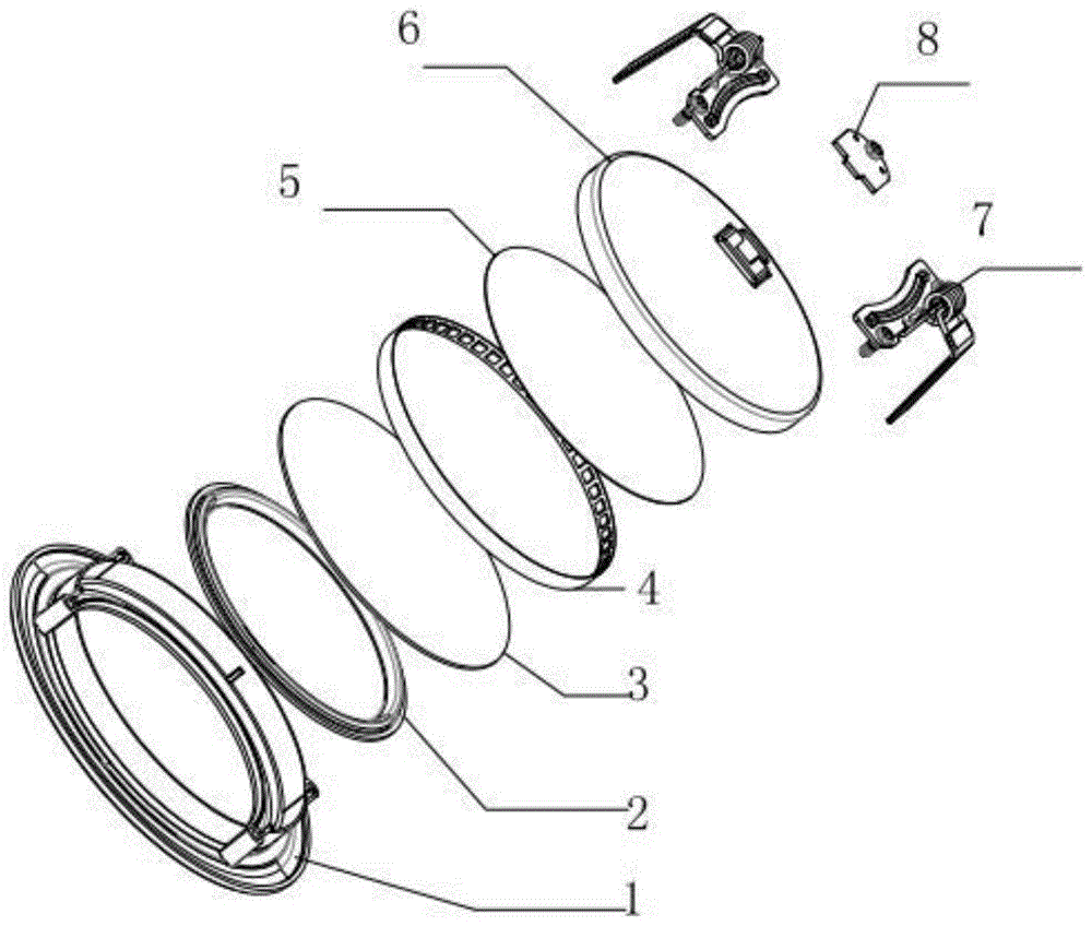
Fig. 1 is an exploded view of the present invention.
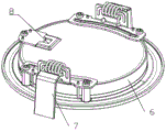
Fig. 2 is a schematic view of the overall structure of the present invention.
Fig. 3 is a side view of the present invention.
Fig. 4 is a cross-sectional view a-a of fig. 3 of the present invention.
Fig. 5 is a schematic diagram of a second optical device of the present invention.
FIG. 6 is a schematic diagram of a curved second optical device according to the present invention.
Fig. 7 is an enlarged view of the invention at B in fig. 6.
Fig. 8 is a schematic diagram of a wedge-shaped second optic of the present invention.
Fig. 9 is a schematic diagram of a frontal sawtooth-shaped second optical device structure according to the present invention.
Fig. 10 is an enlarged view at C in fig. 9 of the present invention.
In the figure: 1. the LED light source comprises a shell 2, a light diffusion device 3, a second optical device 4, an LED light source 5, a first optical device 5-1, a specular reflection layer 5-2, a diffuse reflection unit 6, a rear cover 7, a spring fitting 8, a power line fixing cover plate 9, an optical cavity 10, an air layer theta i, an incident angle h, a height d, a distance a1 and an included angle.
Detailed Description
The invention is further described with reference to the following detailed description and accompanying drawings. It should be noted that as used in the foregoing description, the terms "front," "back," "left," "right," "upper" and "lower" refer to directions in the drawings, and the terms "inner" and "outer" refer to directions toward and away from, respectively, the geometric center of a particular component.
Example 1:
in the embodiment shown in fig. 1 to 4, a side-emitting lamp without a light guide plate comprises a housing with a mounting slot and an LED light source 4 arranged in the housing, wherein the housing comprises a shell 1 and a rear cover 6, the LED light source is welded on a flexible substrate in the form of annular patches by using light-emitting particles, and the flexible substrate is fixed on the rear cover through a back adhesive. The light-emitting surface of the shell opening is provided with a light diffusion device 2 which is milk white and is used for homogenizing light. The rear cover is provided with a spring fitting 7, a power line fixing cover plate 8, a driver and the like.
The side-emitting lamp further comprises a first optical device 5 and a light-permeable second optical device 3, the first optical device and the second optical device are both disc-shaped, the first optical device is arranged at the bottom of the mounting slotted hole of the shell, the second optical device is arranged above the first optical device and forms an optical cavity 9 with the first optical device, air is filled in the optical cavity, and the optical cavity is used for mixing light. As shown in fig. 5, the first optical device includes a specular reflection layer 5-1 and a plurality of diffuse reflection units 5-2 disposed on the specular reflection layer in a dot array, the diffuse reflection units being gradually dense from the edge to the center of the specular reflection layer. Similarly, the first optical device may be a mirror reflection unit including a diffuse reflection layer and a plurality of mirror reflection units arranged at intervals on the diffuse reflection layer, and the mirror reflection units are gradually thinned from the edge of the diffuse reflection layer to the center. The mirror reflection layer comprises a support body and a plating layer arranged on one side of the support body, the support body is sheet-shaped, the thickness of the support body is 2mm, the support body is made of PET (polyethylene terephthalate) materials, or other thin sheet metal materials or high polymer materials, the plating layer is made of aluminum materials, or other mirror materials, and the thickness of the plating layer is 200 mu m. The diffuse reflection unit protrudes from the surface of the specular reflection layer, is 40 microns high, is arc-shaped or square, can be made of titanium dioxide powder and transparent optical adhesive, has the characteristics of high diffuse reflection rate and no light absorption, and is fixed to the specular reflection layer in a printing mode. The second optical device is made of transparent optical materials with certain strength and thickness. In addition, the first optical device may also be configured with a plurality of specular reflection units arranged on the diffuse reflection layer at intervals, and the specular reflection units are gradually sparse along the direction away from the LED light source.
Preferably, the solar cell further comprises a plurality of temperature control devices, the specular reflection layer is divided into a plurality of annular sub-regions corresponding to the temperature control devices, the sub-regions are sequentially nested from the middle part to the edge of the specular reflection layer, the regions with the similar illumination intensity are classified into the same sub-region, the temperature control devices are arranged in one-to-one correspondence with the sub-regions, a filling cavity is arranged on one side, close to the installation slot hole, of the specular reflection layer and corresponds to each diffuse reflection unit, the filling cavity is communicated to the inside of the diffuse reflection unit, reversible temperature-sensitive color-changing materials are arranged in the filling cavity, and the heating end of each temperature control device is close to or in contact with the reversible temperature-sensitive color-changing materials in each filling cavity in the corresponding sub-region. In the optimization, the depth of the color of the reversible temperature-sensitive color-changing material can be controlled by the temperature control device, the subregion temperature-sensitive color-changing material close to the LED lamp source is adjusted to be dark, the subregion in the middle is adjusted to be light, the adjustability is increased, and the light-emitting uniformity of the lamp is improved.
This scheme light axial is like: when light emitted by the LED lamp source and facing the first optical device is incident on the first optical device, most of the light is reflected to the second optical device through the mirror surface, and a small part of the light is reflected to the second optical device through the diffuse reflection after encountering the diffuse reflection unit; the light emitted by the LED lamp source and facing the second optical device is reflected on the interface and enters the optical cavity, the other part of the light is refracted and enters the second optical device, and the light directly passing through the second optical device for the first time and the light reflected by the mirror surface and the diffuse reflection of the first optical device are reflected and refracted and mixed in the air layer 10 outside the second optical device again to form uniform light emission. This scheme adopts first optical device, the light guide plate is replaced to the second optical device, first optical device has reflection and diffuse reflection function, first optical device can be the structure of the diffuse reflection unit of a plurality of intervals setting on the specular reflection layer, diffuse reflection unit is along keeping away from LED lamp source direction intensive gradually, replace the back plane of reflection of light guide plate, specular reflection and diffuse reflection function can adopt the light material among the prior art to realize, the second optical device of light-permeable also can adopt the light material, this scheme has good light effect, lamps and lanterns surface lighting is even, save the light guide plate and reduced the cost under the circumstances of guaranteeing the effect.
Example 2: in the embodiments shown in fig. 6 to 8, a side-emitting luminaire without a light guide plate has a structure substantially the same as that of embodiment 1, except that: the second optical device is convex towards the side far away from the first optical device, as shown in figure 6, the second optical device is in a curved surface shape, and the second optical device adopts a PC board.
Since the reflectivity and the incidence angle satisfy:
Rs=|(n1cosθi-n2cosθt)/(n1cosθi+n2cosθt)|^2=|(n1cosθi-n2√(〖1-(n1/n2 sinθi)〗^2)/(n1cosθi+n2√(〖1-(n1/n2 sinθi)〗^2)))|^2
Rp=|n1cosθt-n2cosθi)/(n1cosθt+n2cosθi)|^2=|(n1√(〖1-(n1/n2 sinθi)〗^2)-n2cosθi)/(n1√(〖1-(n1/n2 sinθi)〗^2)+n2cosθi)|^2
R=1/2(Rs+Rp)
wherein: r is the reflectance, Rs is the s component perpendicular to the incident surface light vector, Rp is the p component parallel to the incident surface light vector, θ i is the incident angle, θ t is the intermediate variable, n1 is 1, n2 is 1.59, in this embodiment, n2 is the refractive index of the PC board, and other optical materials may be used, and n2 is the refractive index of the corresponding material. With the increase of the incident angle, the reflectivity is larger, the energy close to the LED light source is large, and a bright ring area is often easily formed. As shown in fig. 8, preferably, the second optical device includes a first surface block and a second surface block, where an included angle a1 between the first surface block close to the LED light source and the first optical device is 5 degrees, the second surface block is centered and arranged in parallel with the first optical device, and is connected to the first surface block, and its cross section is similar to a wedge shape, compared with a curved surface structure, the structure can avoid an increase in incident angle of the surface block in the middle, and an increase in incident angle of an area close to the LED light source increases reflectivity at the edge, thereby improving uniformity of light extraction.
Example 3:
as shown in fig. 9 and 10, a side-emitting lamp without a light guide plate has a structure substantially the same as that of embodiment 2, except that one side of the second optical device close to the first optical device is provided with a saw-toothed annular microstructure, the other side is a plane, the height h of the saw-toothed annular microstructure is 50-200 μm, the pitch d of the microstructures and the ratio h/d are sequentially decreased to 0 from 0.5 at the edge of the second optical device to the center direction thereof, so as to improve the uniformity of light extraction, and the principle of the side-emitting lamp is the same as that of embodiment 2, so that the side-emitting lamp is more flat and compact in structure and reduces the thickness of the lamp compared with embodiment 2.
Therefore, the invention can save a light guide plate, reduce the cost, reduce the weight of the lamp, and has high light utilization rate and good light emitting uniformity.
It will be appreciated by those of ordinary skill in the art that the examples described herein are intended to assist the reader in understanding the manner in which the invention is practiced, and it is to be understood that the scope of the invention is not limited to such specifically recited statements and examples. Those skilled in the art can make various other specific changes and combinations based on the teachings of the present invention without departing from the spirit of the invention, and these changes and combinations are within the scope of the invention.