CN113211730A - Injection mold with linkage type back-off demolding mechanism - Google Patents
Injection mold with linkage type back-off demolding mechanism Download PDFInfo
- Publication number
- CN113211730A CN113211730A CN202110405001.4A CN202110405001A CN113211730A CN 113211730 A CN113211730 A CN 113211730A CN 202110405001 A CN202110405001 A CN 202110405001A CN 113211730 A CN113211730 A CN 113211730A
- Authority
- CN
- China
- Prior art keywords
- die
- mold
- core
- linkage type
- plate
- Prior art date
- Legal status (The legal status is an assumption and is not a legal conclusion. Google has not performed a legal analysis and makes no representation as to the accuracy of the status listed.)
- Pending
Links
- 238000002347 injection Methods 0.000 title claims abstract description 22
- 239000007924 injection Substances 0.000 title claims abstract description 22
- 238000000034 method Methods 0.000 claims abstract description 31
- 150000001875 compounds Chemical class 0.000 claims abstract description 25
- 238000007599 discharging Methods 0.000 claims abstract description 18
- 230000000670 limiting effect Effects 0.000 claims description 25
- 238000001125 extrusion Methods 0.000 claims description 15
- 230000000149 penetrating effect Effects 0.000 claims description 4
- 238000012163 sequencing technique Methods 0.000 claims description 4
- 238000004519 manufacturing process Methods 0.000 abstract description 11
- 238000001746 injection moulding Methods 0.000 description 13
- 238000000926 separation method Methods 0.000 description 11
- 239000000306 component Substances 0.000 description 7
- 230000000694 effects Effects 0.000 description 3
- 238000005299 abrasion Methods 0.000 description 2
- 230000001427 coherent effect Effects 0.000 description 2
- 238000001816 cooling Methods 0.000 description 2
- 238000010586 diagram Methods 0.000 description 2
- 238000000465 moulding Methods 0.000 description 2
- 230000002265 prevention Effects 0.000 description 2
- 230000002035 prolonged effect Effects 0.000 description 2
- 230000009286 beneficial effect Effects 0.000 description 1
- 239000003086 colorant Substances 0.000 description 1
- 238000010276 construction Methods 0.000 description 1
- 239000008358 core component Substances 0.000 description 1
- 238000007493 shaping process Methods 0.000 description 1
- 230000003245 working effect Effects 0.000 description 1
Images


Classifications
-
- B—PERFORMING OPERATIONS; TRANSPORTING
- B29—WORKING OF PLASTICS; WORKING OF SUBSTANCES IN A PLASTIC STATE IN GENERAL
- B29C—SHAPING OR JOINING OF PLASTICS; SHAPING OF MATERIAL IN A PLASTIC STATE, NOT OTHERWISE PROVIDED FOR; AFTER-TREATMENT OF THE SHAPED PRODUCTS, e.g. REPAIRING
- B29C45/00—Injection moulding, i.e. forcing the required volume of moulding material through a nozzle into a closed mould; Apparatus therefor
- B29C45/17—Component parts, details or accessories; Auxiliary operations
- B29C45/26—Moulds
- B29C45/33—Moulds having transversely, e.g. radially, movable mould parts
-
- B—PERFORMING OPERATIONS; TRANSPORTING
- B29—WORKING OF PLASTICS; WORKING OF SUBSTANCES IN A PLASTIC STATE IN GENERAL
- B29C—SHAPING OR JOINING OF PLASTICS; SHAPING OF MATERIAL IN A PLASTIC STATE, NOT OTHERWISE PROVIDED FOR; AFTER-TREATMENT OF THE SHAPED PRODUCTS, e.g. REPAIRING
- B29C45/00—Injection moulding, i.e. forcing the required volume of moulding material through a nozzle into a closed mould; Apparatus therefor
- B29C45/17—Component parts, details or accessories; Auxiliary operations
- B29C45/40—Removing or ejecting moulded articles
- B29C45/4005—Ejector constructions; Ejector operating mechanisms
-
- B—PERFORMING OPERATIONS; TRANSPORTING
- B29—WORKING OF PLASTICS; WORKING OF SUBSTANCES IN A PLASTIC STATE IN GENERAL
- B29C—SHAPING OR JOINING OF PLASTICS; SHAPING OF MATERIAL IN A PLASTIC STATE, NOT OTHERWISE PROVIDED FOR; AFTER-TREATMENT OF THE SHAPED PRODUCTS, e.g. REPAIRING
- B29C45/00—Injection moulding, i.e. forcing the required volume of moulding material through a nozzle into a closed mould; Apparatus therefor
- B29C45/17—Component parts, details or accessories; Auxiliary operations
- B29C45/40—Removing or ejecting moulded articles
- B29C45/44—Removing or ejecting moulded articles for undercut articles
- B29C2045/445—Removing or ejecting moulded articles for undercut articles using the movable undercut forming element for ejection of the moulded article
Abstract
The invention discloses an injection mold with a linkage type back-off demolding mechanism, which comprises a mold body, wherein the mold body comprises an upper compound plate and a lower compound plate, a cavity is arranged below the upper compound plate, mold feet are arranged above the lower compound plate, a base plate is arranged on the mold feet, and a mold core is arranged on the base plate; the die comprises a die body, a linkage type back-off demoulding mechanism and a control module, wherein the die body is provided with the linkage type back-off demoulding mechanism which comprises a linkage type order-separating die opening assembly and an inclined ejection back-off die opening assembly; and between the die opening action of the die cavity-base plate and the die opening action of the die core-die cavity, the inclined ejection reverse-buckling discharging die assembly obliquely ejects a reverse-buckling product to complete the reverse-buckling discharging action. Through the linkage type sequence-dividing die opening assembly and the inclined ejection and back-off die discharging assembly, the situation that in the die opening process, the inclined ejection and back-off product of the inclined ejection and back-off die discharging assembly in an inclined roadway is ejected to finish back-off action and realize demoulding can be guaranteed, and the production efficiency is remarkably improved.
Description
Technical Field
The invention relates to the technical field of mold manufacturing, in particular to an injection mold with a linkage type back-off demolding mechanism.
Background
Injection molding is a method for producing and molding industrial products. The products are generally produced by rubber injection molding and plastic injection molding. The injection molding method has the advantages of high production speed, high efficiency, automation of operation, various colors, various shapes from simple to complex, small sizes, accurate product size, easy replacement of products, capability of forming products with complex shapes, and suitability for the molding processing fields of mass production, products with complex shapes and the like.
In the injection molding of plastic products, some plastic product structures are usually provided with a ring-shaped inverted buckle or an inward recess, and the plastic products cannot be taken out of a mold core through a conventional ejection mechanism after being molded. Special designs are required to address this problem.
For example, chinese patent document (publication No. CN 203876172U) discloses a "undercut-removing assembly and a mold comprising the same", the mold comprising the undercut-removing assembly, the undercut-removing assembly comprises a straight top and an inclined top block, the inclined top block is arranged in an inclined channel on the straight top in a penetrating manner, the inclined top block is provided with a hook head portion hooked with an undercut of a model product and a guide block which penetrates through an outer wall of the straight top and is limited by a mold core, the guide block is fixedly arranged on at least one side of the inclined top block, the outer wall of the straight top is provided with a limiting groove for accommodating and limiting the guide block, and when a limiting effect of the mold core on the guide block in an axial direction of the limiting groove disappears, the guide block slides along the limiting groove.
According to the technical scheme, the limiting groove provides a yielding space for the guide sliding block which is separated from the limiting of the mold core, so that the undercut removing effect is realized, but the undercut removing effect of the scheme is limited by the size of the limiting groove, when the size of an undercut part of a formed product is larger, no enough space is provided for arranging the large-size limiting groove on the mold, the limiting groove formed by hollowing increases along with the size, and the structural strength of the mold is also reduced; more importantly, the scheme needs manual die sinking work for separating the upper compound plate and the upper half die cavity, a space is reserved for ejecting a product, otherwise, the step of taking off the reverse buckle is blocked, the automatic demoulding scheme is low in efficiency, and production efficiency and labor cost are affected.
Disclosure of Invention
Aiming at the problems that the prior injection mold cannot realize the cooperative completion of the mold opening action and the inverse buckle type demolding action, and has low production efficiency, high labor cost and the like, the invention provides the injection mold with the linkage type inverse buckle type demolding mechanism.
In order to achieve the purpose, the invention adopts the following technical scheme:
an injection mold with a linkage type back-off demolding mechanism comprises a mold body, wherein the mold body comprises an upper compound plate and a lower compound plate, a cavity is arranged below the upper compound plate, mold feet are arranged above the lower compound plate, a base plate is arranged on the mold feet, and a mold core is arranged on the base plate; the die comprises a die body, a linkage type back-off demoulding mechanism and a control module, wherein the die body is provided with the linkage type back-off demoulding mechanism which comprises a linkage type order-separating die opening assembly and an inclined ejection back-off die opening assembly;
the linkage type sequential die opening assembly is used for dividing the die opening actions of the die cavity and the base plate into a die cavity-base plate die opening action and a die core-die cavity die opening action; and between the die opening action of the die cavity-base plate and the die opening action of the die core-die cavity, the inclined ejection reverse-buckling discharging die assembly obliquely ejects a reverse-buckling product to complete the reverse-buckling discharging action. In the traditional injection molding process, after the mold is integrally cooled, the molded product is ejected out of a mold core to complete demolding, but when the molded product is in an inverted buckle state, an inverted buckle removing procedure is required to be added to assist demolding, in the application, an ejection mold opening process is divided into two processes of cavity-base plate mold opening and mold core-cavity mold opening through a linkage type sequential mold opening assembly, the mold core is ejected away from the base plate for a certain distance in the first process and then is stopped, the mold core and the base plate are stopped from being separated, and at the moment, the ejection is continued and the molded product is ejected obliquely by utilizing an oblique ejection inverted buckle removing mold outlet assembly to realize the inverted buckle removing; and continuously ejecting to start a second process, wherein the linked sequential die opening assembly acts to separate the die cavity from the core until the die opening is finished, and the molded product is smoothly ejected to finish the die releasing. The continuous ejection action can ensure that the two processes of die opening of the die cavity-cushion plate and die opening of the die core-die cavity are carried out continuously, and manual auxiliary adjustment of die parts is not needed to realize the action of back-off, so that the production efficiency is effectively improved.
Preferably, the linkage type sequencing die sinking assembly comprises a hook arranged on the die cavity, and a telescopic block is arranged on the die core corresponding to the hook; correspond the movable block on the backing plate and be provided with the footstock, be provided with the chamber that holds that the cover fits flexible piece in the footstock, it is provided with the opening to hold the chamber top, the couple stretches into in the footstock and articulates flexible piece from the opening, it is provided with the extrusion portion to hold the chamber upper wall, flexible piece top corresponds the extrusion portion and is provided with the bevel connection, the extrusion portion can shift up the in-process at the bevel connection and inwards extrude flexible piece. In a die assembly state, the hook is hooked with the bottom of the telescopic block, and the width of the telescopic block is larger than that of the hook; in the die opening process of the die cavity and the base plate, the die cavity and the die core are synchronously jacked up, the hook and the telescopic block maintain a hitching state at the moment, after the die opening process of the die cavity and the base plate is finished, the inclined ejection of a formed product is synchronously realized by obliquely ejecting a reverse-buckling die-discharging assembly, and the die core and the base plate are stopped to be separated because the base plate is limited due to the continuous action of ejecting force at the moment, so the die cavity generates a tendency of separating the die core; the couple that sets up on the core this moment articulates with the flexible piece on the die cavity, and backing plate and footstock are spacing, and the core is at ejecting in-process, and flexible piece top bevel connection butt footstock holds the extrusion portion of intracavity, and flexible piece is to being close to the shrink of mould middle part position under the effect of horizontal component, and couple and flexible piece break away from, and die cavity and core separation. The ejection force is utilized to realize the step-by-step execution of the two separation actions, and the back-off action is realized between the two separation actions, so that the structure is simple, and the efficiency is remarkably improved.
Further, an ejector plate is arranged between the base plate and the lower compound plate, an ejector rod is arranged on the ejector plate, and the top end of the ejector rod penetrates through the mold core and then abuts against the bottom of the back-off product. The ejector pin plate and the ejector pins on the ejector pin plate are used as ejection parts of a molded product and used for driving step-by-step separation in the mold opening process of the injection mold, other driving parts are not needed in the mold opening process, and smooth realization of 'mold cavity-base plate mold opening action-inclined ejection reversing action-mold core-mold cavity mold opening action' can be guaranteed only by a step-by-step separation scheme.
Further, the inclined ejection demoulding assembly comprises an inclined ejection base arranged on the ejector plate, an inclined ejector rod penetrating through the base plate is arranged on the inclined ejection base, the bottom end of the inclined ejector rod is fixedly connected with the inclined ejection base, an inclined ejector block is arranged at the top end of the inclined ejector rod, and the inclined ejector block is abutted to the bottom of the inverted product. The angle of inclination of the oblique ejector block is determined by the oblique ejector base and the oblique ejector block at two points, in the upward moving process of the ejector plate, the oblique ejector rod and the ejector rod synchronously carry out upward ejection, and the oblique ejector rod carries out oblique ejection on the formed product along the preset angle, so that the product is taken off and inverted without additional operation.
Furthermore, an inclined top guide sliding sleeve is arranged in an inner hole through which the inclined top rod penetrates on the mold core, and the inclined top rod is in sliding connection with the inclined top reverse sliding sleeve. The inclined top guide sliding sleeve is used as a sleeve, so that the friction force of the inclined top rod can be reduced, the inclined top rod can be ejected more smoothly, less abrasion can be caused, and the service life of the die is prolonged.
Preferably, the inclined top undercut demolding component further comprises a core pulling component, the core pulling component comprises a pulling block arranged on the base plate, a core pulling guide block is arranged on the pulling block, a core pulling sliding block is connected to the core pulling guide block, and a wear-resistant block connected to the mold core is arranged below the core pulling sliding block. When backing plate and core separation, the guide block of loosing core drive slider of loosing core, loose core the slider with wear-resisting piece contact can't slide to produce inside action of loosing core and make the slider of loosing core promote the shaping product to break away from the back-off, accomplish the die sinking and loose core and take off the back-off and also make the slider of loosing core break away from oblique top and take off the back-off and go out the mould subassembly simultaneously, guarantee to push off to one side and take off the back-off and go out the mould subassembly and can ejecting completion.
Preferably, the core pulling slide block is provided with a slide way, the core pulling guide block is provided with a guide rail, and the slide way is in sliding connection with the guide rail. The core-pulling sliding block can slide on the core-pulling guide block, so that the inclined ejector rod is avoided, and the interference influence of the contact back-off state is avoided, so that the inclined ejector rod can be smoothly ejected obliquely for demolding.
Preferably, a runner plate is arranged between the upper compound plate and the cavity, and an injection molding runner penetrates through the runner plate. The important passage between the injection runner from the main runner to the gate is the flow passage of the molten plastic ejected from the nozzle of the injection molding machine. The injection molding runner has the characteristics of low resistance and cooling prevention.
Therefore, the invention has the following beneficial effects: (1) through the cooperation of the linkage type sequencing die opening assembly and the inclined top inverted buckle removing and discharging assembly, the inclined top inverted buckle removing and discharging assembly can eject inverted buckle products out in an inclined roadway to complete inverted buckle removing action and realize demoulding in the die opening process only through a conventional die opening program, so that the die structure is effectively simplified, the manual work participation procedures are reduced, the coherent actions of die opening, inverted buckle removing and demoulding are realized, and the production efficiency is remarkably improved; (2) the continuous ejection action can ensure that the two processes of the die opening of the die cavity-the base plate and the die opening of the die core-the die cavity are carried out continuously, and the manual auxiliary adjustment of die parts is not needed to realize the action of back-off, so that the production efficiency is effectively improved; (3) the core-pulling slide block is matched with the inclined ejector rod, interference is eliminated through core-pulling action between two separation actions, so that the inclined ejector stripping inverted buckle mold discharging assembly smoothly strips inverted buckles and ejects a molded product, the action is coherent, and the working effect is ideal.
Drawings
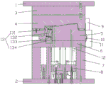
FIG. 1 is a schematic structural diagram of a mold clamping state of the invention;
FIG. 2 is a schematic diagram of the mold-opened state of the present invention;
FIG. 3 is a schematic view of the demolded construction of the present invention;
FIG. 4 is a schematic structural view of an exemplary angle ejector undercut ejector assembly;
in the figure: 1-upper compound plate, 2-lower compound plate, 3-runner plate, 4-cavity, 5-core, 6-backing plate, 7-mould foot, 8-ejector plate, 9-hook, 10-telescopic block, 101-bevel mouth, 11-footstock, 111-containing cavity, 12-limiting rod, 13-loose core component, 131-loose core slide block, 132-loose core guide block, 133-wear-resistant block, 134-loose block, 14-oblique top stripping and back-off mould-out component, 141-oblique top block, 142-oblique ejector rod, 143-oblique top guide sliding sleeve, 144-oblique top base and 15-ejector rod.
Detailed Description
The invention is further described with reference to the following detailed description and accompanying drawings. Examples of which are illustrated in the accompanying drawings, wherein like reference numerals refer to the same or similar elements or elements having the same or similar function throughout. The embodiments described below with reference to the drawings are illustrative and intended to be illustrative of the invention and are not to be construed as limiting the invention.
In the description of the present invention, it is to be understood that the terms "center", "width", "thickness", "upper", "lower", "front", "rear", "left", "right", "vertical", "horizontal", "top", "bottom", "inner", "outer", and the like, indicate orientations or positional relationships based on those shown in the drawings, and are used only for convenience in describing the present invention and for simplicity in description, and do not indicate or imply that the device or element being referred to must have a particular orientation, be constructed in a particular orientation, and be operated, and thus, should not be construed as limiting the present invention.
In the present invention, unless otherwise expressly stated or limited, the terms "mounted," "connected," "secured," and the like are to be construed broadly and can, for example, be fixedly connected, detachably connected, or integrally formed; can be mechanically or electrically connected; either directly or indirectly through intervening media, either internally or in any other relationship. The specific meanings of the above terms in the present invention can be understood by those skilled in the art according to specific situations.
Example 1
As shown in fig. 1 and 2, an injection mold with a linkage type back-off demolding mechanism comprises a mold body, wherein the mold body comprises an upper compound plate 1 and a lower compound plate 2, a cavity 4 is arranged below the upper compound plate 1, mold feet 7 are arranged above the lower compound plate 2, a base plate 6 is arranged on the mold feet 7, and a mold core 5 is arranged on the base plate 6; the die comprises a die body, a linkage type back-off demoulding mechanism and a control module, wherein the die body is provided with the linkage type back-off demoulding mechanism which comprises a linkage type sequential die opening assembly and an inclined ejecting back-off demoulding assembly 14; the linkage type sequential die opening assembly is used for dividing the die opening action of the die cavity 4 and the base plate 6 into die opening of the die cavity 4-the base plate 6 and die opening of the die core 5-the die cavity 4; wherein, between the die opening action of the die cavity 4-the backing plate 6 and the die opening action of the die core 5-the die cavity 4, the inclined ejection reverse-buckling discharging die assembly 14 obliquely ejects a reverse-buckling product to complete the reverse-buckling discharging action. An ejector plate 8 is arranged between the backing plate 6 and the lower compound plate 2, an ejector rod 15 is arranged on the ejector plate 8, and the top end of the ejector rod 15 penetrates through the mold core 5 and then abuts against the bottom of the back-off product. The ejector pin plate 8 and the ejector pins 15 on the ejector pin plate are used as ejection parts of a molded product and used for driving step-by-step separation in the mold opening process of the injection mold, other driving parts are not needed in the mold opening process, and smooth realization of mold opening action of the cavity 4-the base plate 6, mold opening action of inclined ejection and back-off action, mold opening action of the core 5-the cavity 4 can be ensured only by a step-by-step separation scheme.
As shown in fig. 3, in the conventional injection molding process, after the mold is integrally cooled, the molded product is ejected from the mold core 5 to complete demolding, but when the molded product is in an inverted buckle state, an inverted buckle removing process is required to be added to assist demolding, in the application, the ejection and mold opening process is divided into two processes of mold opening of the mold cavity 4-the cushion plate 6 and mold opening of the mold core 5-the mold cavity 4 by a linkage type sequential mold opening assembly, the mold core 5 is ejected away from the cushion plate 6 for a certain distance in the first process and then is stopped separating, and at this time, the ejection is continued and the molded product is ejected obliquely by the oblique-ejection inverted buckle removing mold outlet assembly 14 to realize the inverted buckle removal; and continuously ejecting to start a second process, wherein the linked sequential die opening assembly acts to separate the die cavity 4 from the die core 5, and the die opening is finished, so that the molded product is smoothly ejected to finish the die releasing. The continuous ejection action can ensure that the die opening processes of the die cavity 4-the base plate 6 and the die opening processes of the die core 5-the die cavity 4 are carried out continuously, and manual auxiliary adjustment of die parts is not needed to realize the back-off action, so that the production efficiency is effectively improved.
The linkage type sequencing die sinking assembly comprises a hook 9 arranged on the die cavity 4, and a telescopic block 10 is arranged on the die core 5 corresponding to the hook 9; correspond the movable block on the backing plate 6 and be provided with footstock 11, be provided with the cover in the footstock 11 and close in the chamber 111 that holds of flexible piece 10, it is provided with the opening to hold chamber 111 top, couple 9 stretches into footstock 11 from the opening and articulates flexible piece 10, it is provided with the extrusion portion to hold chamber 111 upper wall, flexible piece 10 top corresponds the extrusion portion and is provided with bevel 101, the extrusion portion can shift up in-process extrusion flexible piece 10 inwards at bevel 101. In a die closing state, the hook 9 is hooked with the bottom of the telescopic block 10; in the die sinking process of the die cavity 4-the backing plate 6, the die cavity 4 and the die core 5 are synchronously jacked up, at the moment, the hook 9 and the telescopic block 10 maintain a hanging state, when the die core 5 and the backing plate 6 are separated to a certain stroke, the limiting head of the limiting rod 12 plays a limiting role on the die core 5, the die core 5 and the backing plate 6 stop separating, the bevel opening 101 at the top of the telescopic block 10 is contacted with the extrusion block at the top of the containing cavity 111 to generate extrusion force to separate the movable block from the draw hook, and the die sinking is continued to separate the die core 5 from the die cavity 4 to achieve the die sinking action.
The inclined ejection stripping and back-off mold discharging assembly 14 comprises an inclined ejection base 144 arranged on an ejector plate 8, an inclined ejector rod 15142 penetrating through the backing plate 6 is arranged on the inclined ejection base 144, the bottom end of the inclined ejector rod 15142 is fixedly connected with the inclined ejection base 144, an inclined ejection block 141 is arranged at the top end, and the inclined ejection block 141 abuts against the bottom of a back-off product. Further, an inclined top guide sliding sleeve 143 is arranged in an inner hole through which the inclined top rod 15142 of the mold core 5 penetrates, and the inclined top rod 15142 is connected with an inclined top reverse sliding sleeve in a sliding mode. The inclined ejection base 144 is fixed on the ejector plate 8, the inclined ejector rod 15142 has a similar function with the ejector rod 15 and is a part for ejecting a formed product, the difference is that the inclined ejector rod 15142 is arranged at an angle of falling and reversing, namely the position of a part needing falling and reversing on the formed product is preset, the position of the inclined ejection base 144, namely the inclined ejection block 141 is preset, the inclination angle of the inclined ejection block 141 is determined by the two points of the inclined ejection base 144 and the inclined ejection block 141, in the upward movement process of the ejector plate 8, the inclined ejector rod 15142 and the ejector rod 15 synchronously eject, and the inclined ejector rod 15142 obliquely ejects the formed product along the preset angle, so that the falling and reversing of the product are realized without additional operation. The inclined ejection guide sliding sleeve 143 serves as a sleeve, so that the friction force of the inclined ejection rod 15142 can be reduced, the ejection is smoother, less abrasion can be caused, and the service life of the die is prolonged.
As shown in fig. 4, the inclined ejecting and back-off mold discharging assembly 14 further includes a core pulling assembly 13, the core pulling assembly 13 includes a pulling block 134 disposed on the backing plate 6, a core pulling guide block 132 is disposed on the pulling block 134, a core pulling slider 131 is connected to the core pulling guide block 132, and a wear-resistant block 133 connected to the core 5 is disposed below the core pulling slider 131. The core pulling slide block 131 is provided with a slide way, the core pulling guide block 132 is provided with a guide rail, and the slide way is in sliding connection with the guide rail. When the base plate 6 is separated from the mold core 5, the core pulling guide block 132 drives the core pulling slide block 131, the core pulling slide block 131 is contacted with the wear-resisting block 133 and cannot slide downwards, so that inward core pulling action is generated to enable the core pulling slide block 131 to push a molded product to be separated from an inverted buckle, the mold opening and core pulling inverted buckle removal are completed, the core pulling slide block 131 is separated from the inclined top and inverted buckle removal mold discharging assembly 14, and the inclined top and inverted buckle removal mold discharging assembly 14 can be ejected smoothly to complete mold release. The core-pulling slider 131 can slide on the core-pulling guide block 132, so as to avoid the inclined ejector rod 15142 and contact the interference influence of the inverted buckling state, and the inclined ejector rod 15142 can be smoothly ejected obliquely for demoulding.
A runner plate 3 is arranged between the upper compound plate 1 and the cavity 4, and an injection molding runner penetrates through the runner plate 3. The important passage between the injection runner from the main runner to the gate is the flow passage of the molten plastic ejected from the nozzle of the injection molding machine. The injection molding runner has the characteristics of low resistance and cooling prevention.
As shown in fig. 1, 2 and 3, in the mold opening process of the mold cavity 4-the backing plate 6, the mold cavity 4 and the mold core 5 are synchronously jacked up, at this time, the hook 9 and the telescopic block 10 maintain a hanging state, when the mold core 5 and the backing plate 6 are separated to a certain stroke, the limiting head of the limiting rod 12 has a limiting effect on the mold core 5, the mold core 5 and the backing plate 6 stop separating, the inclined opening 101 at the top of the telescopic block 10 abuts against the extrusion part in the accommodating cavity 111 of the top seat 11, the telescopic block 10 contracts towards the middle part of the mold under the action of transverse component force, extrusion force is generated to separate the movable block from the draw hook, at this time, the core pulling guide block 132 drives the core pulling slide block 131, the core pulling slide block 131 and the wear-resistant block 133 are contacted and can not slide down, so that the core pulling slide block 131 is separated from the back-off, and the core pulling slide block 131 is separated from the inclined ejector rod 15142, thereby ensuring that the inclined ejector block 141 can be ejected smoothly to complete the mold stripping, and continuing opening the mold to separate the mold core 5 from the mold cavity 4 to achieve mold opening action. And the inclined ejection demoulding component 14 synchronously realizes the inclined ejection of the formed product, and at the moment, the cavity 4 is separated from the core 5 due to the continuous action of ejection force. The ejection force is utilized to realize the step-by-step execution of the two separation actions, and the back-off action is realized between the two separation actions, so that the structure is simple, and the efficiency is remarkably improved.
In addition to the above embodiments, the technical features of the present invention can be re-selected and combined to form new embodiments within the scope of the claims and the specification of the present invention, which are all realized by those skilled in the art without creative efforts, and thus, the embodiments of the present invention which are not described in detail should be regarded as the specific embodiments of the present invention and are within the protection scope of the present invention.
Claims (9)
1. An injection mold with a linkage type back-off demolding mechanism is characterized by comprising a mold body, wherein the mold body comprises an upper compound plate and a lower compound plate, a cavity is arranged below the upper compound plate, mold feet are arranged above the lower compound plate, a base plate is arranged on the mold feet, and a mold core is arranged on the base plate;
the die comprises a die body, a linkage type back-off demoulding mechanism and a control module, wherein the die body is provided with the linkage type back-off demoulding mechanism which comprises a linkage type order-separating die opening assembly and an inclined ejection back-off die opening assembly;
the linkage type sequential die opening assembly is used for dividing the die opening actions of the die cavity and the base plate into a die cavity-base plate die opening action and a die core-die cavity die opening action;
and between the die opening action of the die cavity-base plate and the die opening action of the die core-die cavity, the inclined ejection reverse-buckling discharging die assembly obliquely ejects a reverse-buckling product to complete the reverse-buckling discharging action.
2. The injection mold with the linkage type back-off demolding mechanism according to claim 1, wherein the linkage type sequential opening mold assembly comprises a hook arranged on a mold cavity, and a telescopic block is arranged on the mold core corresponding to the hook; correspond the movable block on the backing plate and be provided with the footstock, be provided with the chamber that holds that the cover fits flexible piece in the footstock, it is provided with the opening to hold the chamber top, the couple stretches into in the footstock and articulates flexible piece from the opening, it is provided with the extrusion portion to hold the chamber upper wall, flexible piece top corresponds the extrusion portion and is provided with the bevel connection, the extrusion portion can shift up the in-process at the bevel connection and inwards extrude flexible piece.
3. The injection mold with the linkage type back-off demolding mechanism according to claim 1, wherein the linkage type sequencing mold opening assembly comprises a limiting rod, an ejector plate is connected to the bottom of the limiting rod, a limiting head penetrates through a base plate and is arranged at the top of the limiting rod, the limiting head is clamped on the top surface of the limiting base plate, and the base plate can slide up and down relative to the limiting rod.
4. The injection mold with the linkage type back-off demolding mechanism according to claim 1, wherein an ejector plate is arranged between the backing plate and the lower compound plate, an ejector rod is arranged on the ejector plate, and the top end of the ejector rod penetrates through the mold core and then abuts against the bottom of a back-off product.
5. The injection mold with the linkage type back-off demolding mechanism according to claim 4, wherein the inclined ejecting and back-off demolding assembly comprises an inclined ejecting base arranged on the ejector plate, an inclined ejector rod penetrating through the backing plate is arranged on the inclined ejecting base, the bottom end of the inclined ejector rod is fixedly connected with the inclined ejecting base, an inclined ejecting block is arranged at the top end of the inclined ejector rod, and the inclined ejecting block abuts against the bottom of the back-off product.
6. The injection mold with the linkage type back-off demolding mechanism according to claim 5, wherein an inclined top guide sliding sleeve is arranged in an inner hole through which the inclined top rod on the mold core penetrates, and the inclined top rod is in sliding connection with the inclined top back-off sliding sleeve.
7. The injection mold with the linkage type back-off demolding mechanism according to claim 1, characterized in that the inclined ejecting back-off demolding assembly further comprises a core pulling assembly, the core pulling assembly comprises a pulling block arranged on the base plate, a core pulling guide block is arranged on the pulling block, a core pulling slider is connected to the core pulling guide block, and a wear-resistant block connected to the core is arranged below the core pulling slider.
8. The injection mold with the linkage type back-off demolding mechanism according to claim 7, wherein a slide way is arranged on the core-pulling slide block, a guide rail is arranged on the core-pulling guide block, and the slide way is slidably connected with the guide rail.
9. The injection mold with the linkage type back-off demolding mechanism according to any one of claims 1 to 8, wherein a runner plate is arranged between the upper compound plate and the cavity, and an injection runner penetrates through the runner plate.
Priority Applications (1)
| Application Number | Priority Date | Filing Date | Title |
|---|---|---|---|
| CN202110405001.4A CN113211730A (en) | 2021-04-15 | 2021-04-15 | Injection mold with linkage type back-off demolding mechanism |
Applications Claiming Priority (1)
| Application Number | Priority Date | Filing Date | Title |
|---|---|---|---|
| CN202110405001.4A CN113211730A (en) | 2021-04-15 | 2021-04-15 | Injection mold with linkage type back-off demolding mechanism |
Publications (1)
| Publication Number | Publication Date |
|---|---|
| CN113211730A true CN113211730A (en) | 2021-08-06 |
Family
ID=77087353
Family Applications (1)
| Application Number | Title | Priority Date | Filing Date |
|---|---|---|---|
| CN202110405001.4A Pending CN113211730A (en) | 2021-04-15 | 2021-04-15 | Injection mold with linkage type back-off demolding mechanism |
Country Status (1)
| Country | Link |
|---|---|
| CN (1) | CN113211730A (en) |
Cited By (1)
| Publication number | Priority date | Publication date | Assignee | Title |
|---|---|---|---|---|
| CN114953270A (en) * | 2022-04-21 | 2022-08-30 | 株洲时代瑞唯减振装备有限公司 | Sequential time-delay die opening die and method for back-off foaming product |
Citations (4)
| Publication number | Priority date | Publication date | Assignee | Title |
|---|---|---|---|---|
| CN202668908U (en) * | 2012-06-01 | 2013-01-16 | 浙江凯华模具有限公司 | Clamp jaw type secondary demoulding mechanism for injection mould |
| CN203141780U (en) * | 2013-02-21 | 2013-08-21 | 台州市凯华塑业有限公司 | Side core-pulling mechanism at side of injection mold cavity |
| CN203210628U (en) * | 2013-04-19 | 2013-09-25 | 台州市凯华塑业有限公司 | Dog-leg cam oblique inner core pulling mechanism of injection mold |
| CN205364434U (en) * | 2016-02-01 | 2016-07-06 | 台州市黄岩永明车灯模具厂 | Car door plant blanking cover injection mold's secondary ejection mechanism |
-
2021
- 2021-04-15 CN CN202110405001.4A patent/CN113211730A/en active Pending
Patent Citations (4)
| Publication number | Priority date | Publication date | Assignee | Title |
|---|---|---|---|---|
| CN202668908U (en) * | 2012-06-01 | 2013-01-16 | 浙江凯华模具有限公司 | Clamp jaw type secondary demoulding mechanism for injection mould |
| CN203141780U (en) * | 2013-02-21 | 2013-08-21 | 台州市凯华塑业有限公司 | Side core-pulling mechanism at side of injection mold cavity |
| CN203210628U (en) * | 2013-04-19 | 2013-09-25 | 台州市凯华塑业有限公司 | Dog-leg cam oblique inner core pulling mechanism of injection mold |
| CN205364434U (en) * | 2016-02-01 | 2016-07-06 | 台州市黄岩永明车灯模具厂 | Car door plant blanking cover injection mold's secondary ejection mechanism |
Non-Patent Citations (1)
| Title |
|---|
| 曾霞文等, 西安电子科技大学出版社 * |
Cited By (2)
| Publication number | Priority date | Publication date | Assignee | Title |
|---|---|---|---|---|
| CN114953270A (en) * | 2022-04-21 | 2022-08-30 | 株洲时代瑞唯减振装备有限公司 | Sequential time-delay die opening die and method for back-off foaming product |
| CN114953270B (en) * | 2022-04-21 | 2023-05-26 | 株洲时代瑞唯减振装备有限公司 | Sequential time delay die sinking die and method for reverse buckling foaming product |
Similar Documents
| Publication | Publication Date | Title |
|---|---|---|
| CN113103524A (en) | Inside oblique top of injection mold takes off back-off mechanism | |
| CN209350829U (en) | A kind of Double-ejection injection mold | |
| CN113211730A (en) | Injection mold with linkage type back-off demolding mechanism | |
| CN110919995A (en) | Anti-adhesion demolding structure for slider-wrapped annular product | |
| CN1064590C (en) | Method and mold for molding slide fastener slider body | |
| CN211138010U (en) | Secondary sliding block demoulding mechanism for complex area of automobile rearview mirror | |
| CN212795716U (en) | Oblique ejection die | |
| CN209999631U (en) | Flange forming die of washing machine | |
| CN205661002U (en) | Injection mold of three punishment profile structures | |
| CN219133137U (en) | Double-shot injection mold convenient for demolding of horizontal core-pulling slide insert | |
| CN218429774U (en) | Die set | |
| CN109968634A (en) | A method of increasing blow molded product local wall thickness | |
| CN115431471B (en) | Injection mold for sample cup | |
| CN211165127U (en) | Lateral auxiliary sliding block demoulding mechanism for side wall of automobile bumper | |
| CN212194059U (en) | Back-off demoulding structure | |
| CN215619715U (en) | Plastic garbage bin footing distance drag hook side forming mechanism of loosing core | |
| CN213107901U (en) | Injection mold of vehicle-mounted backlight module | |
| CN216708243U (en) | Sliding block pouring handle firm moving die mechanism of automobile headlamp double-color decorative frame injection mold | |
| CN212194037U (en) | Runner gate structure of plastic mold integral tensile deformation | |
| CN211763110U (en) | B plate ejection driving rear mold large tunnel core pulling mechanism | |
| CN220661631U (en) | Quick ejection mechanism | |
| CN215320365U (en) | Demoulding mechanism | |
| CN218615262U (en) | Automobile rear bumper electroplating decoration strip mold with sliding block glue feeding mechanism | |
| CN210910991U (en) | Combined cover die with anti-demolding function | |
| CN217622012U (en) | Plastic chair mold with combined inclined top demolding mechanism |
Legal Events
| Date | Code | Title | Description |
|---|---|---|---|
| PB01 | Publication | ||
| PB01 | Publication | ||
| SE01 | Entry into force of request for substantive examination | ||
| SE01 | Entry into force of request for substantive examination | ||
| RJ01 | Rejection of invention patent application after publication | ||
| RJ01 | Rejection of invention patent application after publication |
Application publication date: 20210806 |