CN113211552B - Plank cutting equipment for building materials - Google Patents
Plank cutting equipment for building materials Download PDFInfo
- Publication number
- CN113211552B CN113211552B CN202110499460.3A CN202110499460A CN113211552B CN 113211552 B CN113211552 B CN 113211552B CN 202110499460 A CN202110499460 A CN 202110499460A CN 113211552 B CN113211552 B CN 113211552B
- Authority
- CN
- China
- Prior art keywords
- plate
- supporting
- plates
- connecting plate
- push
- Prior art date
- Legal status (The legal status is an assumption and is not a legal conclusion. Google has not performed a legal analysis and makes no representation as to the accuracy of the status listed.)
- Active
Links
- 238000005520 cutting process Methods 0.000 title claims abstract description 23
- 239000004566 building material Substances 0.000 title claims abstract description 11
- 238000004140 cleaning Methods 0.000 claims abstract description 15
- 230000010405 clearance mechanism Effects 0.000 claims abstract description 8
- 239000012535 impurity Substances 0.000 abstract description 3
- 239000002023 wood Substances 0.000 description 13
- 238000004804 winding Methods 0.000 description 4
- 230000000694 effects Effects 0.000 description 3
- 238000004519 manufacturing process Methods 0.000 description 3
- 230000001681 protective effect Effects 0.000 description 2
- 238000010926 purge Methods 0.000 description 2
- 239000002699 waste material Substances 0.000 description 2
- 230000009286 beneficial effect Effects 0.000 description 1
- 230000007547 defect Effects 0.000 description 1
- 238000010586 diagram Methods 0.000 description 1
- 239000000463 material Substances 0.000 description 1
Images


Classifications
-
- B—PERFORMING OPERATIONS; TRANSPORTING
- B27—WORKING OR PRESERVING WOOD OR SIMILAR MATERIAL; NAILING OR STAPLING MACHINES IN GENERAL
- B27B—SAWS FOR WOOD OR SIMILAR MATERIAL; COMPONENTS OR ACCESSORIES THEREFOR
- B27B5/00—Sawing machines working with circular or cylindrical saw blades; Components or equipment therefor
- B27B5/16—Saw benches
- B27B5/18—Saw benches with feedable circular saw blade, e.g. arranged on a carriage
-
- B—PERFORMING OPERATIONS; TRANSPORTING
- B27—WORKING OR PRESERVING WOOD OR SIMILAR MATERIAL; NAILING OR STAPLING MACHINES IN GENERAL
- B27B—SAWS FOR WOOD OR SIMILAR MATERIAL; COMPONENTS OR ACCESSORIES THEREFOR
- B27B29/00—Gripping, clamping or holding devices for the trunk or log in saw mills or sawing machines; Travelling trunk or log carriages
- B27B29/02—Clamping angles; Gripping equipment thereon
-
- B—PERFORMING OPERATIONS; TRANSPORTING
- B27—WORKING OR PRESERVING WOOD OR SIMILAR MATERIAL; NAILING OR STAPLING MACHINES IN GENERAL
- B27B—SAWS FOR WOOD OR SIMILAR MATERIAL; COMPONENTS OR ACCESSORIES THEREFOR
- B27B31/00—Arrangements for conveying, loading, turning, adjusting, or discharging the log or timber, specially designed for saw mills or sawing machines
- B27B31/08—Discharging equipment
-
- B—PERFORMING OPERATIONS; TRANSPORTING
- B27—WORKING OR PRESERVING WOOD OR SIMILAR MATERIAL; NAILING OR STAPLING MACHINES IN GENERAL
- B27B—SAWS FOR WOOD OR SIMILAR MATERIAL; COMPONENTS OR ACCESSORIES THEREFOR
- B27B5/00—Sawing machines working with circular or cylindrical saw blades; Components or equipment therefor
- B27B5/29—Details; Component parts; Accessories
-
- B—PERFORMING OPERATIONS; TRANSPORTING
- B27—WORKING OR PRESERVING WOOD OR SIMILAR MATERIAL; NAILING OR STAPLING MACHINES IN GENERAL
- B27G—ACCESSORY MACHINES OR APPARATUS FOR WORKING WOOD OR SIMILAR MATERIALS; TOOLS FOR WORKING WOOD OR SIMILAR MATERIALS; SAFETY DEVICES FOR WOOD WORKING MACHINES OR TOOLS
- B27G3/00—Arrangements for removing bark-zones, chips, waste, or dust, specially designed for use in connection with wood-working machine or in wood-working plants
-
- Y—GENERAL TAGGING OF NEW TECHNOLOGICAL DEVELOPMENTS; GENERAL TAGGING OF CROSS-SECTIONAL TECHNOLOGIES SPANNING OVER SEVERAL SECTIONS OF THE IPC; TECHNICAL SUBJECTS COVERED BY FORMER USPC CROSS-REFERENCE ART COLLECTIONS [XRACs] AND DIGESTS
- Y02—TECHNOLOGIES OR APPLICATIONS FOR MITIGATION OR ADAPTATION AGAINST CLIMATE CHANGE
- Y02P—CLIMATE CHANGE MITIGATION TECHNOLOGIES IN THE PRODUCTION OR PROCESSING OF GOODS
- Y02P70/00—Climate change mitigation technologies in the production process for final industrial or consumer products
- Y02P70/10—Greenhouse gas [GHG] capture, material saving, heat recovery or other energy efficient measures, e.g. motor control, characterised by manufacturing processes, e.g. for rolling metal or metal working
Landscapes
- Life Sciences & Earth Sciences (AREA)
- Engineering & Computer Science (AREA)
- Mechanical Engineering (AREA)
- Wood Science & Technology (AREA)
- Forests & Forestry (AREA)
- Dovetailed Work, And Nailing Machines And Stapling Machines For Wood (AREA)
- Sawing (AREA)
Abstract
The invention relates to cutting equipment, in particular to board cutting equipment for building materials. The technical problems to be solved are as follows: provided is a plank cutting device for building materials, which can realize automatic cutting and automatic cleaning. The technical proposal is as follows: the utility model provides a plank cutting equipment for building materials, including bottom plate, first support frame, cylinder, first connecting plate, first connecting axle, safety cover and saw bit, bottom plate one side is equipped with first support frame, is equipped with the cylinder on the first support frame, and cylinder one side is equipped with first connecting plate, and the last rotation of first connecting plate is connected with first connecting axle, is equipped with the safety cover on the first connecting plate, and safety cover and first connecting axle rotation are connected, are equipped with the saw bit on the first connecting axle. Through the cooperation between placing mechanism and the clearance mechanism, can realize carrying out automatic cutout to the plank, can clear up impurity simultaneously, just so need not manual operation, labour saving and time saving.
Description
Technical Field
The invention relates to cutting equipment, in particular to board cutting equipment for building materials.
Background
At present, most wood board cutting machines on the market cut wood boards by moving blades, wherein the blades are driven by a high-speed motor, the high-speed motor in the work is required to be moved directionally, the difficulty is high, the danger is high, the cutting machine is inaccurate in positioning, the waste of wood is easily caused, the production cost is increased, the cutting effect is poor, and the production efficiency is seriously influenced; in addition, for cutting a wood board or wood with a larger size, accurate scribing is required, the size is adjusted, but the situation of position deviation in the cutting process is easy to occur.
Thus, a plank cutting device for building materials, which can realize automatic cutting and automatic cleaning, is developed.
Disclosure of Invention
In order to overcome the defects that the positioning of a cutting machine is inaccurate, wood is easy to waste, the cutting effect is poor, and the production efficiency is seriously influenced, the technical problem to be solved is that: provided is a plank cutting device for building materials, which can realize automatic cutting and automatic cleaning.
The technical proposal is as follows: the utility model provides a plank cutting equipment for building materials, including bottom plate, first support frame, the cylinder, first connecting plate, first connecting axle, the safety cover, the warning light, the saw bit, placing mechanism and clearance mechanism, bottom plate one side is equipped with first support frame, be equipped with the cylinder on the first support frame, cylinder one side is equipped with first connecting plate, the rotation is connected with first connecting axle on the first connecting plate, be equipped with the safety cover on the first connecting plate, safety cover and first connecting axle rotation are connected, be equipped with the saw bit on the first connecting axle, safety cover one side is equipped with the warning light, bottom plate one side is equipped with placing mechanism, be equipped with clearance mechanism on the first connecting plate.
Further, the placing mechanism comprises supporting feet, a mounting plate, placing plates and a sliding plate, the supporting feet are arranged on four sides of the bottom plate, the placing plates are connected between the tops of the supporting feet, the mounting plate is connected to the tops of the placing plates, and the sliding plate is arranged on one side of the bottoms of the placing plates.
Further, the cleaning mechanism comprises a second support frame, a second connecting shaft, a first spring, a first push plate, a cleaning brush and a connecting block, wherein the second support frame is arranged on one side of the mounting plate, the second connecting shaft is connected to the second support frame in a sliding mode, the first push plate is arranged on one side of the second connecting shaft, the first spring is connected between one side of the first push plate and the second support frame, the cleaning brush is arranged at the bottom of the first push plate, and the connecting block is connected between one side of the first push plate and the first connecting plate.
Further, the novel automatic feeding device comprises a feeding mechanism, wherein the feeding mechanism comprises a U-shaped connecting plate, a push rod and a push block, the U-shaped connecting plate is connected between one sides of the mounting plates, the push rod is connected in the middle of the U-shaped connecting plate in a sliding mode, and the push block is arranged on one side of the push rod.
Further, still including clamping mechanism, clamping mechanism is including first backup pad, the bolt, the second spring, the second connecting plate, the connecting rod, the telescopic link, rubber clamp splice and third spring, all be equipped with first backup pad in the middle of the mounting panel, threaded connection has the bolt between the mounting panel of first backup pad and homonymy, sliding connection has the second connecting plate between the first backup pad, second connecting plate one side evenly is equipped with the connecting rod, all be equipped with the second spring between second connecting plate bottom both sides and the first backup pad, second connecting plate bottom sliding connection has two telescopic links, the telescopic link bottom all is equipped with the rubber clamp splice, all be equipped with the third spring between telescopic link top and the second connecting plate.
Further, the reminding device also comprises a reminding mechanism, wherein the reminding mechanism comprises a second supporting plate, a third connecting shaft and a screwdrivers ball, the second supporting plate is arranged on one side of the top of the second supporting frame, the third connecting shaft is rotatably connected to the second supporting plate, and the screwdrivers ball is arranged on one side of the third connecting shaft.
Further, the automatic feeding device comprises a feeding mechanism, the feeding mechanism comprises a feeding plate, a rotating shaft, a spiral spring, a third supporting plate, a fixing rod, a winding wheel, a third supporting frame, a sliding rail, a fourth spring and a third connecting plate, wherein the rotating shafts are respectively connected to two sides of the mounting plate, the feeding plate is rotatably connected between the rotating shafts, the spiral spring is respectively arranged between the feeding plate and the rotating shafts, the third supporting plate is arranged on one side of the bottom plate, the fixing rod is respectively arranged on two sides and the rear side of the third supporting plate, the fixing rod is respectively rotatably connected with the winding wheel, the third supporting frame is arranged on one side of the mounting plate, the sliding rail is arranged on one side of the third supporting frame, the third connecting plate is connected with the third spring, the fourth spring is connected between the rear side of the third connecting plate and the sliding rail, the pull wire is connected between one side bottom of the feeding plate and the third connecting plate, and the pull wire bypasses the winding wheel.
Further, the blanking plate is cuboid.
The invention has the beneficial effects that: 1. through the cooperation between placing mechanism and the clearance mechanism, can realize carrying out automatic cutout to the plank, can clear up impurity simultaneously, just so need not manual operation, labour saving and time saving.
2. Through the cooperation between pushing equipment and the clamping mechanism, can realize pushing away the material to the plank, can press from both sides tight effect to the plank simultaneously.
Drawings
Fig. 1 is a schematic diagram of a front view structure of the present invention.
Fig. 2 is a schematic perspective view of a first part of the present invention.
Fig. 3 is a schematic perspective view of a second part of the present invention.
Fig. 4 is a schematic perspective view of a third portion of the present invention.
Fig. 5 is a schematic perspective view of a fourth part of the present invention.
Fig. 6 is a schematic perspective view of a fifth part of the present invention.
Fig. 7 is a schematic perspective view of a sixth part of the present invention.
Fig. 8 is a schematic perspective view of a seventh part of the present invention.
Reference numerals: 1_floor, 2_first support, 3_cylinder, 4_first connection, 5_first connection, 6_boot, 7_warning light, 8_saw blade, 9_mechanism, 90_support leg, 91_second support, 92_placement plate, 93_slide, 10_purge mechanism, 100_second support, 101_second connection, 102_first spring, 103_first push plate, 104_purge brush, 105_connection, 11_pushing mechanism, 110_u-shaped connection, 111_push rod, 112_push block, 12_clamping mechanism, 120_first support plate, 121_bolt, 122_second spring, 123_second connection plate, 124_connection rod, 125_telescoping rod, 126_rubber clamp block, 127_third spring, 13_reminder mechanism, 130_second support plate, 131_third connection shaft, 132_tip ball, 14_blanking mechanism, 140_blanking plate, 141_spindle, 142_scroll spring, 143_third support plate, 144_fixed bar, 146_spring, 148_spring, and wire winding frame, 148_spring, and a third connection plate.
Detailed Description
The present invention will be described in detail with reference to the accompanying drawings.
Example 1
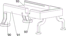
1-3, including bottom plate 1, first support frame 2, cylinder 3, first connecting plate 4, first connecting axle 5, safety cover 6, warning light 7, saw bit 8, placing mechanism 9 and clearance mechanism 10, bottom plate 1 right front side is equipped with first support frame 2, be equipped with cylinder 3 on the first support frame 2, cylinder 3 rear side is equipped with first connecting plate 4, the rotation type is connected with first connecting axle 5 on the first connecting plate 4, be equipped with safety cover 6 on the first connecting plate 4, safety cover 6 and first connecting axle 5 rotation type are connected, be equipped with saw bit 8 on the first connecting axle 5, safety cover 6 upper right side is equipped with warning light 7, bottom plate 1 rear side is equipped with placing mechanism 9, be equipped with clearance mechanism 10 on the first connecting plate 4.
The placing mechanism 9 comprises supporting legs 90, a mounting plate 91, placing plates 92 and a sliding plate 93, wherein the supporting legs 90 are arranged on four sides of the rear portion of the bottom plate 1, the placing plates 92 are connected between the tops of the supporting legs 90, the mounting plate 91 is connected to the tops of the placing plates 92, and the sliding plate 93 is arranged on the right side of the bottom of the placing plates 92.
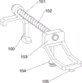
The cleaning mechanism 10 comprises a second support frame 100, a second connecting shaft 101, a first spring 102, a first push plate 103, a cleaning brush 104 and a connecting block 105, wherein the second support frame 100 is arranged on the right rear side of the mounting plate 91, the second support frame 100 is connected with the second connecting shaft 101 in a sliding mode, the front side of the second connecting shaft 101 is provided with the first push plate 103, the first spring 102 is connected between the rear side of the first push plate 103 and the second support frame 100, the cleaning brush 104 is arranged at the bottom of the first push plate 103, and the connecting block 105 is connected between the bottom of the front side of the first push plate 103 and the first connecting plate 4.
When people need to cut the wood board, firstly, the wood board is placed on the placing plate 92, then the control cylinder 3 stretches to drive the first connecting plate 4, the first connecting shaft 5, the protective cover 6, the warning lamp 7 and the saw blade 8 to move backwards, meanwhile, the saw blade 8 is started, the warning lamp 7 is lightened, the saw blade 8 moves backwards to cut the wood board, the first connecting plate 4 moves backwards to drive the connecting block 105, the first push plate 103, the cleaning brush 104 and the second connecting shaft 101 to move backwards, so that the first spring 102 is compressed, then the control cylinder 3 shortens to drive the first connecting plate 4, the first connecting shaft 5, the protective cover 6, the warning lamp 7 and the saw blade 8 to move forwards, under the action of the first spring 102, the connecting block 105, the first push plate 103, the cleaning brush 104 and the second connecting shaft 101 are driven to move forwards to reset, the cleaning brush 104 cleans impurities, then the saw blade 8 is turned off, and the warning lamp 7 is extinguished.
Example 2
On the basis of embodiment 1, as shown in fig. 4-8, the device further comprises a pushing mechanism 11, wherein the pushing mechanism 11 comprises a U-shaped connecting plate 110, a push rod 111 and a push block 112, the U-shaped connecting plate 110 is connected between the left sides of the mounting plates 91, the push rod 111 is connected in the middle of the U-shaped connecting plate 110 in a sliding manner, and the push block 112 is arranged on the right side of the push rod 111.
When people need to push the plank to the right, the push rod 111 is moved to the right to drive the push block 112 to push the plank to the right, and then the push rod 111 and the push block 112 are moved to the left to reset.
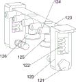
Still including clamping mechanism 12, clamping mechanism 12 is including first backup pad 120, bolt 121, second spring 122, second connecting plate 123, connecting rod 124, telescopic link 125, rubber clamp splice 126 and third spring 127, all be equipped with first backup pad 120 in the middle of the mounting panel 91, threaded connection has bolt 121 between the mounting panel 91 of first backup pad 120 and homonymy, sliding connection has second connecting plate 123 between the first backup pad 120, second connecting plate 123 right part evenly is equipped with connecting rod 124, all be equipped with second spring 122 between both sides and the first backup pad 120 around the second connecting plate 123 bottom, second connecting plate 123 bottom sliding connection has two telescopic links 125, telescopic link 125 bottom all is equipped with rubber clamp splice 126, all be equipped with third spring 127 between telescopic link 125 top and the second connecting plate 123.
When the first push plate 103 moves backwards and contacts the connecting rod 124, the second connecting plate 123, the telescopic rod 125, the rubber clamping block 126 and the third spring 127 move downwards, when the rubber clamping block 126 contacts wood, the second spring 122 and the third spring 127 are compressed, the rubber clamping block 126 clamps the wood, and when the first push plate 103 moves forwards and the connecting rod 124 is separated, the connecting rod 124, the second connecting plate 123, the telescopic rod 125, the rubber clamping block 126 and the third spring 127 are driven to move and reset under the action of the second spring 122 and the third spring 127.
The reminding device further comprises a reminding mechanism 13, wherein the reminding mechanism 13 comprises a second support plate 130, a third connecting shaft 131 and a screwdriving ball 132, the left side of the top of the second support frame 100 is provided with the second support plate 130, the second support plate 130 is rotatably connected with the third connecting shaft 131, and the screwdriving ball 132 is arranged on the right side of the third connecting shaft 131.
When the first push plate 103 moves backwards and contacts with the screwdrivers 132, the screwdrivers 132 can be screwdrivers, so that people can be reminded to cut the wood board, and when the first push plate 103 moves forwards and the screwdrivers 132 are separated, the screwdrivers 132 stop screwdrivers.
The blanking mechanism 14 comprises a blanking plate 140, a rotating shaft 141, a spiral spring 142, a third supporting plate 143, a fixing rod 144, a reel 145, a third supporting frame 146, a sliding rail 147, a fourth spring 148 and a third connecting plate 149, wherein the rotating shaft 141 is connected to the front side and the rear side of the right part of the mounting plate 91, the blanking plate 140 is rotatably connected between the rotating shaft 141, the spiral spring 142 is arranged between the blanking plate 140 and the rotating shaft 141, the third supporting plate 143 is arranged on the right front side of the bottom plate 1, the fixing rods 144 are respectively arranged on the upper side, the lower side and the rear side of the third supporting plate 143, the reel 145 is rotatably connected to the fixing rod 144, the third supporting frame 146 is arranged on the right rear side of the mounting plate 91, the sliding rail 147 is provided with the third connecting plate 149, the fourth spring 148 is connected between the rear side of the third connecting plate 149 and the sliding rail 147, a pull wire is connected between the bottom of the right side of the blanking plate 140 and the third connecting plate 149, and the pull wire bypasses the reel 145.
When the first push plate 103 moves backwards and contacts with the third connecting plate 149, the third connecting plate 149 moves backwards, the fourth spring 148 is compressed, the blanking plate 140 is driven to rotate through the stay wire, the scroll spring 142 is compressed, the wood board is pushed out rightwards, and when the first push plate 103 moves forwards and the third connecting plate 149 are separated, the third connecting plate 149 is driven to move forwards under the action of the fourth spring 148 to loosen the stay wire, and the blanking plate 140 is driven to rotate and reset under the action of the scroll spring 142.
Finally, it should be noted that the above embodiments are only for illustrating the technical solution of the present invention and not for limiting the scope of the present invention, and although the present invention has been described in detail with reference to the preferred embodiments, it should be understood by those skilled in the art that the technical solution of the present invention may be modified or substituted equally without departing from the spirit and scope of the technical solution of the present invention.
Claims (2)
1. The utility model provides a plank cutting equipment for building materials, a serial communication port, including bottom plate (1), first support frame (2), cylinder (3), first connecting plate (4), first connecting axle (5), safety cover (6), warning light (7), saw bit (8), placing mechanism (9) and clearance mechanism (10), bottom plate (1) one side is equipped with first support frame (2), be equipped with cylinder (3) on first support frame (2), cylinder (3) one side is equipped with first connecting plate (4), be connected with first connecting axle (5) on first connecting plate (4) in the rotation, be equipped with safety cover (6) on first connecting plate (4) and first connecting axle (5) in the rotation be connected, be equipped with saw bit (8) on first connecting axle (5), safety cover (6) one side is equipped with warning light (7), bottom plate (1) one side is equipped with placing mechanism (9), be equipped with clearance mechanism (10) on first connecting plate (4).
The placing mechanism (9) comprises supporting feet (90), a mounting plate (91), placing plates (92) and sliding plates (93), the supporting feet (90) are arranged on four sides of the bottom plate (1), the placing plates (92) are connected between the tops of the supporting feet (90), the mounting plate (91) is connected to the tops of the placing plates (92), and the sliding plates (93) are arranged on one side of the bottoms of the placing plates (92);
the cleaning mechanism (10) comprises a second supporting frame (100), a second connecting shaft (101), a first spring (102), a first push plate (103), a cleaning brush (104) and a connecting block (105), wherein the second supporting frame (100) is arranged on one side of the mounting plate (91), the second connecting shaft (101) is connected to the second supporting frame (100) in a sliding mode, the first push plate (103) is arranged on one side of the second connecting shaft (101), the first spring (102) is connected between one side of the first push plate (103) and the second supporting frame (100), the cleaning brush (104) is arranged at the bottom of the first push plate (103), and the connecting block (105) is connected between one side of the first push plate (103) and the first connecting plate (4);
the automatic feeding device is characterized by further comprising a feeding mechanism (11), wherein the feeding mechanism (11) comprises a U-shaped connecting plate (110), a push rod (111) and a push block (112), the U-shaped connecting plate (110) is connected between one sides of the mounting plates (91), the push rod (111) is connected in the middle of the U-shaped connecting plate (110) in a sliding manner, and the push block (112) is arranged on one side of the push rod (111);
the clamping mechanism (12) comprises a first supporting plate (120), bolts (121), a second spring (122), a second connecting plate (123), a connecting rod (124), two telescopic rods (125), rubber clamping blocks (126) and third springs (127), wherein the first supporting plate (120) is arranged in the middle of each mounting plate (91), the bolts (121) are connected between the first supporting plate (120) and the mounting plates (91) on the same side in a threaded mode, the second connecting plates (123) are connected between the first supporting plates (120) in a sliding mode, connecting rods (124) are uniformly arranged on one side of each second connecting plate (123), the second springs (122) are arranged between two sides of the bottom of each second connecting plate (123) and the first supporting plates (120), the two telescopic rods (125) are connected at the bottom of each second connecting plate (123), and the third springs (127) are arranged between the tops of the telescopic rods (125) and the second connecting plates (123);
the portable electronic device is characterized by further comprising a reminding mechanism (13), wherein the reminding mechanism (13) comprises a second supporting plate (130), a third connecting shaft (131) and a screwdriving ball (132), the second supporting plate (130) is arranged on one side of the top of the second supporting frame (100), the third connecting shaft (131) is rotatably connected to the second supporting plate (130), and the screwdriving ball (132) is arranged on one side of the third connecting shaft (131);
the automatic feeding device is characterized by further comprising a feeding mechanism (14), wherein the feeding mechanism (14) comprises a feeding plate (140), a rotating shaft (141), spiral springs (142), a third supporting plate (143), fixing rods (144), a reel (145), third supporting frames (146), sliding rails (147), fourth springs (148) and third connecting plates (149), the rotating shafts (141) are connected to two sides of the mounting plate (91), the feeding plate (140) is rotatably connected between the rotating shafts (141), spiral springs (142) are arranged between the feeding plate (140) and the rotating shafts (141), one side of the bottom plate (1) is provided with the third supporting plate (143), fixing rods (144) are respectively arranged on two sides and the rear side of the third supporting plate (143), the fixing rods (144) are rotatably connected with the reel (145), one side of the mounting plate (91) is provided with the third supporting frames (146), one side of the third supporting frames (146) is provided with the sliding rails (147), the fourth springs (148) are connected between the rear side of the third connecting plates (149) and the sliding rails (147), one side of the bottom plate (140) is connected with the third connecting plates (149), and a wire pulling wire is wound around the reel (145).
2. A board cutting apparatus for building materials according to claim 1, wherein the blanking plate (140) is a rectangular parallelepiped.
Priority Applications (1)
| Application Number | Priority Date | Filing Date | Title |
|---|---|---|---|
| CN202110499460.3A CN113211552B (en) | 2021-05-08 | 2021-05-08 | Plank cutting equipment for building materials |
Applications Claiming Priority (1)
| Application Number | Priority Date | Filing Date | Title |
|---|---|---|---|
| CN202110499460.3A CN113211552B (en) | 2021-05-08 | 2021-05-08 | Plank cutting equipment for building materials |
Publications (2)
| Publication Number | Publication Date |
|---|---|
| CN113211552A CN113211552A (en) | 2021-08-06 |
| CN113211552B true CN113211552B (en) | 2023-05-12 |
Family
ID=77091813
Family Applications (1)
| Application Number | Title | Priority Date | Filing Date |
|---|---|---|---|
| CN202110499460.3A Active CN113211552B (en) | 2021-05-08 | 2021-05-08 | Plank cutting equipment for building materials |
Country Status (1)
| Country | Link |
|---|---|
| CN (1) | CN113211552B (en) |
Families Citing this family (1)
| Publication number | Priority date | Publication date | Assignee | Title |
|---|---|---|---|---|
| CN113976994A (en) * | 2021-11-04 | 2022-01-28 | 顾璟汇 | Pipe cutting equipment for building |
Family Cites Families (5)
| Publication number | Priority date | Publication date | Assignee | Title |
|---|---|---|---|---|
| DE102012022579A1 (en) * | 2012-11-20 | 2014-05-22 | Ima Klessmann Gmbh Holzbearbeitungssysteme | Gantry cutting machine and method for cutting large format boards |
| CN110653882A (en) * | 2018-06-29 | 2020-01-07 | 河南中包科技有限公司 | Wood processing cutting board inserting equipment |
| CN210616792U (en) * | 2019-06-24 | 2020-05-26 | 江苏德鲁尼木业有限公司 | Fast cutting device for wood |
| CN112454538B (en) * | 2020-11-25 | 2022-06-24 | 宁夏绿歌环保科技发展有限公司 | Rotatable formula tenon cutting device |
| CN112571547A (en) * | 2020-12-23 | 2021-03-30 | 刘钰 | Wood cutting equipment for carpenter |
-
2021
- 2021-05-08 CN CN202110499460.3A patent/CN113211552B/en active Active
Also Published As
| Publication number | Publication date |
|---|---|
| CN113211552A (en) | 2021-08-06 |
Similar Documents
| Publication | Publication Date | Title |
|---|---|---|
| CN103722590B (en) | The wood material cutting machine of the multiple cast-cutting saw slice of safety-type band | |
| CN113043390A (en) | Comparatively safe wooden board cutting equipment for building | |
| CN113211552B (en) | Plank cutting equipment for building materials | |
| CN220612489U (en) | Adjustable cutting device | |
| CN113941730B (en) | Municipal administration is with propaganda breast board strip equidistance cut-off device | |
| CN109047906A (en) | Profile sawing device | |
| CN114454235B (en) | Composite floor processing and cutting equipment | |
| CN114101744B (en) | Laser welding positioning clamping plate machining process and device for aviation parts | |
| CN222403649U (en) | Panel unloading cutting device | |
| CN209335247U (en) | It is a kind of automatically to walk blade lathe with protection mechanism | |
| CN112792909A (en) | New energy automobile charger forming device | |
| CN107984510B (en) | Calibration counterpoint formula board cutting machine | |
| CN100534736C (en) | Machine of forming woody brush holder | |
| CN212146799U (en) | Tray disassembling machine | |
| CN114505962B (en) | Automatic cutting equipment for gypsum board | |
| CN208649127U (en) | A kind of glass processing cutter device | |
| CN210389326U (en) | Cutting equipment for the production of sponge cleaning blocks | |
| CN218164147U (en) | Meat bone sawing device | |
| CN219430357U (en) | Fabric cutting machine | |
| CN111283218A (en) | Flange turning device | |
| CN220503542U (en) | Dust-free cloth slitting integrated equipment | |
| CN221561508U (en) | Frock is used in cotton processing of backlight unit bubble | |
| CN222003353U (en) | Equipment maintenance workbench | |
| CN218659307U (en) | High strength ageing resistance reclaimed rubber cutting device | |
| CN220665784U (en) | Tailoring machine for clothing production |
Legal Events
| Date | Code | Title | Description |
|---|---|---|---|
| PB01 | Publication | ||
| PB01 | Publication | ||
| SE01 | Entry into force of request for substantive examination | ||
| SE01 | Entry into force of request for substantive examination | ||
| TA01 | Transfer of patent application right | ||
| TA01 | Transfer of patent application right |
Effective date of registration: 20230419 Address after: Jinyang Village, Huyang Town, Fei County, Linyi City, Shandong Province, 273400 Applicant after: Shandong Luoge Wood Industry Co.,Ltd. Address before: 510700 room 108, comprehensive building, Shiji South Third Street, Huangpu District, Guangzhou, Guangdong Applicant before: Zhong Qipeng |
|
| GR01 | Patent grant | ||
| GR01 | Patent grant |