CN113199706A - Metal insert integrated molding injection mold - Google Patents
Metal insert integrated molding injection mold Download PDFInfo
- Publication number
- CN113199706A CN113199706A CN202110643052.0A CN202110643052A CN113199706A CN 113199706 A CN113199706 A CN 113199706A CN 202110643052 A CN202110643052 A CN 202110643052A CN 113199706 A CN113199706 A CN 113199706A
- Authority
- CN
- China
- Prior art keywords
- insert
- positioning
- lower die
- injection mold
- connecting plate
- Prior art date
- Legal status (The legal status is an assumption and is not a legal conclusion. Google has not performed a legal analysis and makes no representation as to the accuracy of the status listed.)
- Granted
Links
Images


Classifications
-
- B—PERFORMING OPERATIONS; TRANSPORTING
- B29—WORKING OF PLASTICS; WORKING OF SUBSTANCES IN A PLASTIC STATE IN GENERAL
- B29C—SHAPING OR JOINING OF PLASTICS; SHAPING OF MATERIAL IN A PLASTIC STATE, NOT OTHERWISE PROVIDED FOR; AFTER-TREATMENT OF THE SHAPED PRODUCTS, e.g. REPAIRING
- B29C45/00—Injection moulding, i.e. forcing the required volume of moulding material through a nozzle into a closed mould; Apparatus therefor
- B29C45/17—Component parts, details or accessories; Auxiliary operations
- B29C45/26—Moulds
- B29C45/2602—Mould construction elements
-
- B—PERFORMING OPERATIONS; TRANSPORTING
- B29—WORKING OF PLASTICS; WORKING OF SUBSTANCES IN A PLASTIC STATE IN GENERAL
- B29C—SHAPING OR JOINING OF PLASTICS; SHAPING OF MATERIAL IN A PLASTIC STATE, NOT OTHERWISE PROVIDED FOR; AFTER-TREATMENT OF THE SHAPED PRODUCTS, e.g. REPAIRING
- B29C45/00—Injection moulding, i.e. forcing the required volume of moulding material through a nozzle into a closed mould; Apparatus therefor
- B29C45/17—Component parts, details or accessories; Auxiliary operations
- B29C45/26—Moulds
- B29C45/2673—Moulds with exchangeable mould parts, e.g. cassette moulds
-
- B—PERFORMING OPERATIONS; TRANSPORTING
- B29—WORKING OF PLASTICS; WORKING OF SUBSTANCES IN A PLASTIC STATE IN GENERAL
- B29C—SHAPING OR JOINING OF PLASTICS; SHAPING OF MATERIAL IN A PLASTIC STATE, NOT OTHERWISE PROVIDED FOR; AFTER-TREATMENT OF THE SHAPED PRODUCTS, e.g. REPAIRING
- B29C45/00—Injection moulding, i.e. forcing the required volume of moulding material through a nozzle into a closed mould; Apparatus therefor
- B29C45/17—Component parts, details or accessories; Auxiliary operations
- B29C45/40—Removing or ejecting moulded articles
- B29C45/44—Removing or ejecting moulded articles for undercut articles
-
- Y—GENERAL TAGGING OF NEW TECHNOLOGICAL DEVELOPMENTS; GENERAL TAGGING OF CROSS-SECTIONAL TECHNOLOGIES SPANNING OVER SEVERAL SECTIONS OF THE IPC; TECHNICAL SUBJECTS COVERED BY FORMER USPC CROSS-REFERENCE ART COLLECTIONS [XRACs] AND DIGESTS
- Y02—TECHNOLOGIES OR APPLICATIONS FOR MITIGATION OR ADAPTATION AGAINST CLIMATE CHANGE
- Y02P—CLIMATE CHANGE MITIGATION TECHNOLOGIES IN THE PRODUCTION OR PROCESSING OF GOODS
- Y02P70/00—Climate change mitigation technologies in the production process for final industrial or consumer products
- Y02P70/10—Greenhouse gas [GHG] capture, material saving, heat recovery or other energy efficient measures, e.g. motor control, characterised by manufacturing processes, e.g. for rolling metal or metal working
Abstract
The invention discloses an injection mold for integrally molding a metal insert, which comprises: the upper die assembly and the lower die assembly correspond to the upper die assembly; wherein, go up the mould subassembly and include: the upper die frame is internally provided with an upper die core; the lower die assembly includes: the lower die frame is internally provided with a lower die core, and the lower die core is matched with the upper die core; the surface of the lower die core is provided with at least two insert placing parts, and each insert placing part is provided with an insert; at least two first inserts are arranged in the upper die core, and each first insert is positioned right above the corresponding insert placing part. According to the invention, the plurality of first inserts are arranged on the part of the upper die core, which is positioned right above the insert placing part, when the first inserts are damaged, only the first inserts are required to be replaced, the upper die core is not required to be replaced integrally, and the cost is reduced.
Description
Technical Field
The invention relates to the technical field of dies. More particularly, the present invention relates to an injection mold for integrally molding a metal insert.
Background
In the field of mold technology, it is well known to use injection molds of different structural forms to achieve injection molding of products. In the process of researching and realizing injection molding of products, the inventor finds that the injection mold in the prior art has at least the following problems:
firstly, the part of an upper mold core positioned right above an insert placing part in the existing metal insert integrated injection mold is very easy to damage, and when the part of the upper mold core positioned right above the insert placing part is damaged, the upper mold core needs to be integrally replaced and maintained, so that the cost is high; secondly, carry out spacing fixed to the inserts among the current metal insert integrated into one piece injection mold, lead to the inserts at will to move about at the fashioned in-process of product to produce the defective products, increase manufacturing cost, reduce work efficiency.
In view of the above, it is necessary to develop an injection mold for integrally molding a metal insert to solve the above problems.
Disclosure of Invention
Aiming at the defects in the prior art, the invention mainly aims to provide the metal insert integrated injection mold, wherein the plurality of first inserts are arranged on the upper mold core part which is positioned right above the insert placing part, when the first inserts are damaged, only the first inserts are required to be replaced, the upper mold core is not required to be integrally replaced, and the cost is reduced.
Another objective of the present invention is to provide an integrated molding apparatus for metal inserts, which positions and fixes the inserts through an insert positioning module, so as to prevent the inserts from moving randomly during the injection molding process of the mold, thereby resulting in the generation of defective products, increasing the cost, and improving the production efficiency of the injection molding module.
To achieve these objects and other advantages and in accordance with the purpose of the invention, there is provided a metal insert integral molding injection mold comprising: an upper die assembly, and
a lower die assembly corresponding to the upper die assembly;
wherein, go up the mould subassembly and include: the upper die frame is internally provided with an upper die core; the lower die assembly includes: the lower die frame is internally provided with a lower die core, and the lower die core is matched with the upper die core;
the surface of the lower die core is provided with at least two insert placing parts, and each insert placing part is provided with an insert;
at least two first inserts are arranged in the upper die core, each first insert is positioned right above the corresponding insert placing part,
when the upper die assembly and the lower die assembly are assembled along the Z-axis direction, a cavity is defined between the upper die core and the lower die core, and at least part of each insert is positioned in the cavity.
Preferably, the lower die assembly includes: a mandril module which is positioned right below the lower die frame,
the ejector pin module includes: each ejector rod driver is arranged along the Z-axis direction and fixedly installed at the side end of the lower die frame;
the first connecting plate is in transmission connection with the power output end of the ejector rod driver;
the second connecting plate is fixedly arranged right above the first connecting plate; and
the third connecting plate is fixedly arranged right above the second connecting plate;
the surface of the third connecting plate is fixedly connected with at least two push rods, and each push rod penetrates through the lower die core.
Preferably, the ejector pin module further comprises: the two inclined ejecting units are respectively positioned on two sides of the third connecting plate along the Y-axis direction and are fixedly connected with the first connecting plate;
wherein the pitched roof unit includes: forming the inclined top; and
one end of each connecting strip is fixedly connected with the forming pitched roof, and the other end of each connecting strip is fixedly connected with the first connecting plate;
the length of the forming inclined top is slightly smaller than that of the lower die core.
Preferably, at least two second inserts are arranged inside the forming pitched roof, and each second insert is regularly arrayed along the direction of the X axis.
Preferably, the inside of the forming pitched roof is provided with cooling water.
Preferably, the method further comprises the following steps: the insert positioning module is fixedly arranged at the side end of the lower die frame and used for positioning and fixing each insert;
wherein, inserts location module includes: the positioning driver is fixedly arranged on the surface of the lower die frame through a fixing plate;
the movable block is in transmission connection with the power output end of the positioning driver; and
at least two positioning blocks are arranged, and each positioning block is in transmission connection with the movable block;
the positioning driver drives the movable blocks to reciprocate along the X-axis direction, and then drives each positioning block to reciprocate along the Y-axis direction.
Preferably, a surface of each of the insert placing portions is provided with a second positioning portion that is integrally formed with the insert placing portion and extends in the Z-axis direction from the surface of the insert placing portion.
Preferably, the surface of the lower mold core is provided with at least two positioning grooves, and each positioning groove is located beside one corresponding insert placing part.
Preferably, the surface of each insert placing part is provided with at least two first clamping parts;
the surface of the upper die core is provided with at least two second clamping parts;
each second clamping part and the corresponding first clamping part are coaxial along the Z-axis direction.
Preferably, the ejector pin module further comprises: the insert placing part is arranged on the side of the insert placing part, and a third positioning part is arranged at the side end of each positioning inclined top.
One of the above technical solutions has the following advantages or beneficial effects: through last mould benevolence is located the part directly over the inserts portion sets up a plurality of first inserts, when first insert damaged, only need change first insert, need not with go up the whole change of mould benevolence, the cost is reduced.
Another technical scheme in the above technical scheme has the following advantages or beneficial effects: fix a position fixedly to the inserts through inserts positioning module, prevent that the inserts from moving about at will at mould injection moulding's in-process to lead to the production of defective products, the increase cost has improved the production efficiency of the module of moulding plastics simultaneously.
Additional advantages, objects, and features of the invention will be set forth in part in the description which follows and in part will become apparent to those having ordinary skill in the art upon examination of the following or may be learned from practice of the invention.
Drawings
In order to more clearly illustrate the technical solution of the embodiments of the present invention, the drawings of the embodiments will be briefly described below, and it is apparent that the drawings in the following description relate only to some embodiments of the present invention and are not limiting thereof, wherein:
fig. 1 is a three-dimensional structural view of an injection mold for integrally molding a metal insert according to an embodiment of the present invention;
FIG. 2 is a cross-sectional view of a metal insert integrally formed injection mold according to one embodiment of the present invention;
fig. 3 is an exploded view of an injection mold for integrally molding a metal insert according to an embodiment of the present invention;
fig. 4 is an exploded view of an upper mold core, a lower mold core, a lift pin module and an insert positioning module in an injection mold for integrally molding a metal insert according to an embodiment of the present invention;
FIG. 5 is a three-dimensional structural view of an insert positioning module in an injection mold for integrally molding a metal insert according to an embodiment of the present invention;
FIG. 6 is an exploded view of an insert positioning module in an injection mold for integrally molding a metal insert according to an embodiment of the present invention;
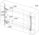
fig. 7 is a three-dimensional structural view of an upper mold core in an injection mold for integrally molding a metal insert according to an embodiment of the present invention;
fig. 8 is a three-dimensional structural view of a lower mold core of an injection mold for integrally molding a metal insert according to an embodiment of the present invention;
fig. 9 is a three-dimensional structural view of a pitched roof unit in an injection mold for integrally molding a metal insert according to an embodiment of the present invention;
FIG. 10 is a cross-sectional view of a molded lifter in an integral metal insert injection mold according to one embodiment of the present invention;
fig. 11 is a three-dimensional structural view of an insert in an injection mold in which a metal insert is integrally formed according to an embodiment of the present invention.
Detailed Description
The technical solutions in the embodiments of the present invention will be described clearly and completely with reference to the accompanying drawings in the embodiments of the present invention, and it is obvious that the described embodiments are only a part of the embodiments of the present invention, and not all of the embodiments. All other embodiments, which can be obtained by a person skilled in the art without any inventive step based on the embodiments of the present invention, are within the scope of the present invention.
In the drawings, the shape and size may be exaggerated for clarity, and the same reference numerals will be used throughout the drawings to designate the same or similar components.
Unless defined otherwise, technical or scientific terms used herein shall have the ordinary meaning as understood by one of ordinary skill in the art to which this invention belongs. The use of "first," "second," and similar terms in the description and claims of the present application do not denote any order, quantity, or importance, but rather the terms are used to distinguish one element from another. Also, the use of the terms "a," "an," or "the" and similar referents do not denote a limitation of quantity, but rather denote the presence of at least one. The word "comprise" or "comprises", and the like, means that the element or item listed before "comprises" or "comprising" covers the element or item listed after "comprising" or "comprises" and its equivalents, and does not exclude other elements or items. "upper", "lower", "left", "right", and the like are used merely to indicate relative positional relationships, and when the absolute position of the object being described is changed, the relative positional relationships may also be changed accordingly.
In the following description, terms such as center, thickness, height, length, front, back, rear, left, right, top, bottom, upper, lower, etc., are defined with respect to the configurations shown in the respective drawings, and in particular, "height" corresponds to a dimension from top to bottom, "width" corresponds to a dimension from left to right, "depth" corresponds to a dimension from front to rear, which are relative concepts, and thus may be varied accordingly depending on the position in which it is used, and thus these or other orientations should not be construed as limiting terms.
Terms concerning attachments, coupling and the like (e.g., "connected" and "attached") refer to a relationship wherein structures are secured or attached, either directly or indirectly, to one another through intervening structures, as well as both movable or rigid attachments, unless expressly described otherwise.
According to an embodiment of the present invention, referring to fig. 1 to 11, it can be seen that the metal insert integrally-formed injection mold includes: an upper die assembly 12, and
a lower die assembly 11 corresponding to the upper die assembly 12;
wherein, go up mould assembly 12 includes: an upper mold frame 122 having an upper mold core 124 therein; the lower die assembly 11 includes: a lower mold frame 112, which is provided with a lower mold core 114 therein, wherein the lower mold core 114 is matched with the upper mold core 124;
the surface of the lower die core 114 is provided with at least two insert placing parts 1141, and each insert placing part 1141 is provided with an insert 14;
at least two first inserts 1242 are provided inside the upper die core 124, each of the first inserts 1242 is positioned right above a corresponding one of the insert-placing portions 1141,
when the upper mold assembly 12 and the lower mold assembly 11 are closed along the Z-axis, a cavity is defined between the upper mold core 124 and the lower mold core 114, and each insert 14 is at least partially located in the cavity.
It can be understood that the portion of the upper mold core 124 directly above the insert placement portion 1141 is very easily damaged, when the portion of the upper mold core 124 directly above the insert placement portion 1141 is damaged, the upper mold core 124 needs to be replaced and maintained as a whole, which is relatively high in cost.
In a preferred embodiment of the present invention, the insert 14 comprises: a grip portion 141;
a first positioning portion 142 integrally formed with the grip portion 141;
a second positioning portion 143 integrally formed with the grip portion 141; and
a third positioning portion 144 integrally formed with the second positioning portion 143;
a first positioning hole 1431 is opened at a top end of the second positioning portion 143, and a third positioning hole 1441 is opened on a surface of the third positioning portion 144.
Further, the lower die assembly 11 includes: a ram module 113 located right below the lower mold frame 112,
the ram module 113 includes: at least two ejector rod drivers 1131, wherein each ejector rod driver 1131 is arranged along the Z-axis direction, and the ejector rod drivers 1131 are fixedly installed at the side end of the lower mold frame 112;
a first connecting plate 1132, which is in transmission connection with the power output end of the ejector rod driver 1131;
a second connection plate 1133 fixedly mounted directly above the first connection plate 1132; and
a third connecting plate 1134 fixedly mounted directly above the second connecting plate 1133;
the surface of the third connecting plate 1133 is fixedly connected with push rods 1136, the number of the push rods 1136 is not less than two, and each push rod 1136 penetrates through the lower mold core 114.
In a preferred embodiment of the present invention, the lower mold assembly 11 further includes: the lower die holder 111, the ejector rod die set 113 is placed in the lower die holder 111;
the upper die assembly 12 further includes: an upper mold plate 121 fixedly installed above the upper mold frame 122; and
and the glue inlet 123 is fixedly arranged on the surface of the upper template 121, and the glue inlet 123 is communicated with the cavity.
Further, the ejector pin module 113 further includes: the two pitched roof units 1137 are respectively located on two sides of the third connecting plate 1134 along the Y-axis direction, and both the two pitched roof units 1137 are fixedly connected with the first connecting plate 1132;
wherein the pent-roof unit 1137 includes: shaped lifter 11371; and
at least two connecting strips 11372, one end of each connecting strip 11372 is fixedly connected to the shaped pitched roof 11371, and the other end of each connecting strip 11372 is fixedly connected to the first connecting plate 1132;
the length of the forming lifter 1371 is slightly less than the length of the lower mold core 114.
It will be appreciated that the use of the shaped lifter 11371, which is slightly shorter in length than the lower core 114, facilitates ejection of the shaped product.
Further, at least two second inserts 11373 are arranged inside the forming pitched roof 11371, and each second insert 11373 is regularly arrayed along the X-axis direction.
It can be understood that at least two second inserts 11373 are arranged inside the forming lifter 11371, and when the second inserts 11373 are damaged, only the second inserts 11373 need to be replaced, and the whole forming lifter 11371 does not need to be replaced, so that the production cost is reduced.
Furthermore, the inside of the forming inclined top 11371 is provided with cooling water conveying 113711.
It will be appreciated that the cooling motion 113711 flows in the direction of the arrows shown in fig. 10 to cool the shaped lifter 11371 to facilitate the shaping of the product.
In a preferred embodiment of the present invention, at least two third inserts 115 are disposed inside the lower mold core 114, and when the third inserts 115 are damaged, only the third inserts 115 need to be replaced, and the entire lower mold core 114 does not need to be replaced, thereby reducing the production cost.
The inner part of the upper die core 124 is also provided with at least two fourth inserts 1243, when the fourth inserts 1243 are damaged, only the fourth inserts 1243 need to be replaced, the whole upper die core 124 does not need to be replaced, and the production cost is reduced.
Further, still include: an insert positioning module 13 fixedly mounted at a side end of the lower mold frame 112, the insert positioning module 13 positioning and fixing each insert 14;
wherein, the insert positioning module 13 includes: a positioning driver 131 fixedly mounted on a surface of the lower mold frame 112 through a fixing plate 132;
a movable block 133, which is in transmission connection with the power output end of the positioning driver 131; and
at least two positioning blocks 134 are provided, and each positioning block 134 is in transmission connection with the movable block 133;
the positioning driver 131 drives the movable block 133 to reciprocate along the X-axis direction, and further drives each positioning block 134 to reciprocate along the Y-axis direction.
It can be understood that the positioning driver 131 drives the movable block 133 to reciprocate along the X-axis direction, and further drives each positioning block 134 to reciprocate along the Y-axis direction, so as to control the positioning blocks 134 to fix or release the insert.
In a preferred embodiment of the present invention, a first positioning portion 1341 is disposed at a side end of each positioning block 134.
The first positioning portion 1341 is adapted to the first positioning hole 1431, and the positioning block 134 is initially positioned and fixed on the insert 14 by the cooperation of the first positioning portion 1341 and the first positioning hole 1431, so as to prevent the insert from moving freely.
Further, a second positioning portion 1142 is provided on a surface of each insert placement portion 1141, and the second positioning portion 1142 is integrally formed with the insert placement portion 1141 and extends from the surface of the insert placement portion 1141 along the Z-axis direction.
In a preferred embodiment of the present invention, the second positioning portion 1142 is adapted to the third positioning hole 1441, and the insert 14 is further positioned and fixed by the cooperation of the second positioning portion 1142 and the third positioning hole 1441, so as to prevent the insert from moving freely.
Further, the surface of the lower mold core 114 is provided with at least two positioning grooves 1143, and each positioning groove 1143 is located beside one corresponding insert placing portion 1141.
In a preferred embodiment of the present invention, the positioning groove 1143 is adapted to the first positioning portion 142, and the positioning groove 1143 and the first positioning portion 142 further position and fix the insert 14, so as to prevent the insert from moving freely.
Further, at least two first clamping portions 1144 are arranged on the surface of each insert placing portion 1141;
the surface of the upper mold core 124 is provided with at least two second clamping portions 1241;
each of the second clamping portions 1241 is coaxial with a corresponding one of the first clamping portions 1144 along the Z-axis direction.
It can be understood that the third positioning portion 144 of the insert 14 is clamped and fixed by the cooperation of the first clamping portion 1144 and the second clamping portion 1241, so that the third positioning portion 144 of the insert 14 is prevented from directly contacting with the upper mold core 124 and the lower mold core 115, and the insert is conveniently copied for the molded product, so that the insert and the product are integrally molded.
Further, the ejector pin module 113 further includes: at least two positioning inclined tops 1135, each positioning inclined top 1135 is located at a side of the insert placing portion 1141, and a third positioning portion 11351 is arranged at a side end of each positioning inclined top 1135.
In a preferred embodiment of the present invention, the third positioning portion 11351 is adapted to the first positioning portion 142, the first positioning portion 142 is placed in the positioning slot 1143, and the third positioning portion 11351 and the positioning slot 1143 together position and fix the insert 14, so as to prevent the insert from moving freely.
The number of apparatuses and the scale of the process described herein are intended to simplify the description of the present invention. Applications, modifications and variations of the present invention will be apparent to those skilled in the art.
While embodiments of the invention have been disclosed above, it is not intended to be limited to the uses set forth in the specification and examples. It can be applied to all kinds of fields suitable for the present invention. Additional modifications will readily occur to those skilled in the art. It is therefore intended that the invention not be limited to the exact details and illustrations described and illustrated herein, but fall within the scope of the appended claims and equivalents thereof.
Claims (10)
1. The utility model provides a metal insert integrated into one piece injection mold which characterized in that includes: an upper die assembly (12), and
a lower die assembly (11) corresponding to the upper die assembly (12);
wherein the upper die assembly (12) comprises: an upper mold frame (122) provided with an upper mold core (124) inside; the lower die assembly (11) includes: the lower die frame (112) is internally provided with a lower die core (114), and the lower die core (114) is matched with the upper die core (124);
the surface of the lower die core (114) is provided with at least two insert placing parts (1141), and each insert placing part (1141) is provided with an insert (14);
at least two first inserts (1242) are arranged in the upper die core (124), each first insert (1242) is positioned right above a corresponding insert placing part (1141),
when the upper die assembly (12) and the lower die assembly (11) are closed along the Z-axis direction, a cavity is defined between the upper die core (124) and the lower die core (114), and each insert (14) is at least partially positioned in the cavity.
2. The metal insert integral molding injection mold according to claim 1, wherein the lower mold assembly (11) comprises: a ram module (113) located directly below the lower mold frame (112),
the ejector pin module (113) includes: at least two ejector rod drivers (1131), wherein each ejector rod driver (1131) is arranged along the Z-axis direction, and the ejector rod drivers (1131) are fixedly installed at the side end of the lower die frame (112);
the first connecting plate (1132) is in transmission connection with the power output end of the ejector rod driver (1131);
a second connecting plate (1133) fixedly mounted directly above the first connecting plate (1132); and
a third connecting plate (1134) fixedly mounted directly above the second connecting plate (1133);
the surface of the third connecting plate (1133) is fixedly connected with push rods (1136), the number of the push rods (1136) is not less than two, and each push rod (1136) penetrates through the lower die core (114).
3. The metal insert integral molding injection mold according to claim 2, wherein the ejector pin module (113) further comprises: the two inclined top units (1137) are respectively positioned on two sides of the third connecting plate (1134) along the Y-axis direction, and the two inclined top units (1137) are fixedly connected with the first connecting plate (1132);
wherein the pitched roof unit (1137) comprises: a profiled lifter (11371); and
at least two connecting strips (11372), one end of each connecting strip (11372) is fixedly connected with the forming pitched roof (11371), and the other end of each connecting strip (11372) is fixedly connected with the first connecting plate (1132);
the length of the forming inclined top (11371) is slightly smaller than that of the lower die core (114).
4. The metal insert integral molding injection mold according to claim 3, wherein the molding lifter (11371) is internally provided with at least two second inserts (11373), and each of the second inserts (11373) is regularly arrayed in the X-axis direction.
5. The metal insert integral molding injection mold according to claim 3, wherein the molding lifter (11371) is internally provided with cooling water (113711).
6. The metal insert integral molding injection mold according to claim 1, further comprising: the insert positioning module (13) is fixedly arranged at the side end of the lower die frame (112), and the insert positioning module (13) is used for positioning and fixing each insert (14);
wherein the insert positioning module (13) comprises: a positioning driver (131) fixedly mounted on the surface of the lower mold frame (112) through a fixing plate (132);
the movable block (133) is in transmission connection with a power output end of the positioning driver (131); and
the number of the positioning blocks (134) is not less than two, and each positioning block (134) is in transmission connection with the movable block (133);
the positioning driver (131) drives the movable block (133) to reciprocate along the X-axis direction, and further drives each positioning block (134) to reciprocate along the Y-axis direction.
7. The metal insert integral molding injection mold according to claim 1, wherein a surface of each insert placement portion (1141) is provided with a second positioning portion (1142), and the second positioning portion (1142) is integrally formed with the insert placement portion (1141) and extends in a Z-axis direction from the surface of the insert placement portion (1141).
8. The metal insert integral molding injection mold according to claim 1, wherein the surface of the lower mold core (114) is provided with at least two positioning grooves (1143), and each positioning groove (1143) is respectively located at the side of a corresponding insert placing portion (1141).
9. The metal insert integral molding injection mold according to claim 1, wherein the surface of each insert placement portion (1141) is provided with at least two first clamping portions (1144);
the surface of the upper die core (124) is provided with at least two second clamping parts (1241);
each second clamping part (1241) and the corresponding first clamping part (1144) are coaxial along the Z-axis direction.
10. The metal insert integral molding injection mold according to claim 2, wherein the ejector pin module (113) further comprises: the insert placing part comprises at least two positioning inclined tops (1135), wherein each positioning inclined top (1135) is located on the side of the insert placing part (1141), and a third positioning part (11351) is arranged at the side end of each positioning inclined top (1135).
Priority Applications (1)
| Application Number | Priority Date | Filing Date | Title |
|---|---|---|---|
| CN202110643052.0A CN113199706B (en) | 2021-06-09 | 2021-06-09 | Injection mold for integrally forming metal inserts |
Applications Claiming Priority (1)
| Application Number | Priority Date | Filing Date | Title |
|---|---|---|---|
| CN202110643052.0A CN113199706B (en) | 2021-06-09 | 2021-06-09 | Injection mold for integrally forming metal inserts |
Publications (2)
| Publication Number | Publication Date |
|---|---|
| CN113199706A true CN113199706A (en) | 2021-08-03 |
| CN113199706B CN113199706B (en) | 2023-07-04 |
Family
ID=77024744
Family Applications (1)
| Application Number | Title | Priority Date | Filing Date |
|---|---|---|---|
| CN202110643052.0A Active CN113199706B (en) | 2021-06-09 | 2021-06-09 | Injection mold for integrally forming metal inserts |
Country Status (1)
| Country | Link |
|---|---|
| CN (1) | CN113199706B (en) |
Cited By (1)
| Publication number | Priority date | Publication date | Assignee | Title |
|---|---|---|---|---|
| CN114131831A (en) * | 2021-12-01 | 2022-03-04 | 上海飞乐汽车控制系统有限公司 | Insert positioning device for injection mold and injection mold |
Citations (9)
| Publication number | Priority date | Publication date | Assignee | Title |
|---|---|---|---|---|
| US5560939A (en) * | 1988-04-28 | 1996-10-01 | Aida Engineering, Ltd. | Mold assembly comprising a sliding mold insert adapted for automated insertion and removal |
| CN204997935U (en) * | 2015-09-25 | 2016-01-27 | 苏州葛雷固普五金科技有限公司 | IO interface injection mold |
| CN206297091U (en) * | 2016-12-21 | 2017-07-04 | 南京建勋塑胶模具有限公司 | Injection mold and mould with mold insert |
| CN108790022A (en) * | 2018-08-10 | 2018-11-13 | 上海徕木电子股份有限公司 | A kind of slide block mechanism for inserts class injecting products |
| CN209794314U (en) * | 2019-02-25 | 2019-12-17 | 深圳市银宝山新科技股份有限公司 | Carbon fiber automobile tail door manufacturing die |
| CN110978421A (en) * | 2019-12-19 | 2020-04-10 | 江苏顺航电子科技有限公司 | Thin-wall part injection mold |
| CN111531829A (en) * | 2020-05-28 | 2020-08-14 | 广东铭利达科技有限公司 | Mould structure |
| CN111730805A (en) * | 2020-07-17 | 2020-10-02 | 潍坊正达实业有限公司 | Accurate positioning device for injection molding insert |
| CN112676548A (en) * | 2020-12-18 | 2021-04-20 | 苏州广型模具有限公司 | Lightweight motor casing die casting die |
-
2021
- 2021-06-09 CN CN202110643052.0A patent/CN113199706B/en active Active
Patent Citations (9)
| Publication number | Priority date | Publication date | Assignee | Title |
|---|---|---|---|---|
| US5560939A (en) * | 1988-04-28 | 1996-10-01 | Aida Engineering, Ltd. | Mold assembly comprising a sliding mold insert adapted for automated insertion and removal |
| CN204997935U (en) * | 2015-09-25 | 2016-01-27 | 苏州葛雷固普五金科技有限公司 | IO interface injection mold |
| CN206297091U (en) * | 2016-12-21 | 2017-07-04 | 南京建勋塑胶模具有限公司 | Injection mold and mould with mold insert |
| CN108790022A (en) * | 2018-08-10 | 2018-11-13 | 上海徕木电子股份有限公司 | A kind of slide block mechanism for inserts class injecting products |
| CN209794314U (en) * | 2019-02-25 | 2019-12-17 | 深圳市银宝山新科技股份有限公司 | Carbon fiber automobile tail door manufacturing die |
| CN110978421A (en) * | 2019-12-19 | 2020-04-10 | 江苏顺航电子科技有限公司 | Thin-wall part injection mold |
| CN111531829A (en) * | 2020-05-28 | 2020-08-14 | 广东铭利达科技有限公司 | Mould structure |
| CN111730805A (en) * | 2020-07-17 | 2020-10-02 | 潍坊正达实业有限公司 | Accurate positioning device for injection molding insert |
| CN112676548A (en) * | 2020-12-18 | 2021-04-20 | 苏州广型模具有限公司 | Lightweight motor casing die casting die |
Cited By (2)
| Publication number | Priority date | Publication date | Assignee | Title |
|---|---|---|---|---|
| CN114131831A (en) * | 2021-12-01 | 2022-03-04 | 上海飞乐汽车控制系统有限公司 | Insert positioning device for injection mold and injection mold |
| CN114131831B (en) * | 2021-12-01 | 2024-04-09 | 上海飞乐汽车控制系统有限公司 | Insert positioning device for injection mold and injection mold |
Also Published As
| Publication number | Publication date |
|---|---|
| CN113199706B (en) | 2023-07-04 |
Similar Documents
| Publication | Publication Date | Title |
|---|---|---|
| CN113199706A (en) | Metal insert integrated molding injection mold | |
| CN107755660B (en) | Mould for producing automobile roof support products | |
| CN112792315B (en) | Lightweight valve body die casting die | |
| CN114571682A (en) | Locking device for closing automobile injection mold | |
| CN213830177U (en) | Quick ejection mechanism for injection mold for auto-parts | |
| CN215825782U (en) | Insert positioning mechanism applied to metal insert integrated injection mold | |
| CN211489484U (en) | Multipurpose combined forging die | |
| CN215619652U (en) | Injection mold for lamp shell of rear tail lamp with large length-width ratio | |
| CN217752572U (en) | Mould inscribe runner mechanism | |
| CN210851130U (en) | Injection mold for automobile safety airbag | |
| CN215550552U (en) | Automobile part injection mold with quick cooling structure | |
| CN113370459B (en) | Metal insert integrated forming device | |
| CN220562080U (en) | Oblique ejection glue feeding mechanism of automobile spoiler body injection mold | |
| CN212636449U (en) | Injection mold with pitched roof structure | |
| CN219190935U (en) | Quick demoulding structure of hydroecium mould | |
| CN216065211U (en) | Stamping die is used in switch board hardware production convenient to drawing of patterns | |
| CN218019820U (en) | Conveniently get large-scale injection mold of vehicle headlamps backshell of membrane | |
| CN217916503U (en) | Auto-parts injection mold | |
| CN215242619U (en) | Bicycle basket injection mold with multiple demoulding blocks | |
| CN215550597U (en) | Mould forming structure of automobile shell part | |
| CN215661534U (en) | Quick blanking structure of accuse panel mould in car | |
| CN216465979U (en) | Motor cavity cover mould convenient to quick drawing of patterns | |
| CN218891104U (en) | High-precision automobile die convenient to cool rapidly | |
| CN213500598U (en) | High-efficient injection mold of multicavity room | |
| CN218777006U (en) | Injection molding mold for automobile door plate |
Legal Events
| Date | Code | Title | Description |
|---|---|---|---|
| PB01 | Publication | ||
| PB01 | Publication | ||
| SE01 | Entry into force of request for substantive examination | ||
| SE01 | Entry into force of request for substantive examination | ||
| GR01 | Patent grant | ||
| GR01 | Patent grant |