CN113134257A - Filter equipment that hydraulic engineering used - Google Patents
Filter equipment that hydraulic engineering used Download PDFInfo
- Publication number
- CN113134257A CN113134257A CN202110504492.8A CN202110504492A CN113134257A CN 113134257 A CN113134257 A CN 113134257A CN 202110504492 A CN202110504492 A CN 202110504492A CN 113134257 A CN113134257 A CN 113134257A
- Authority
- CN
- China
- Prior art keywords
- shell
- filtering
- plates
- sliding
- wall
- Prior art date
- Legal status (The legal status is an assumption and is not a legal conclusion. Google has not performed a legal analysis and makes no representation as to the accuracy of the status listed.)
- Withdrawn
Links
- 238000001914 filtration Methods 0.000 claims abstract description 59
- XLYOFNOQVPJJNP-UHFFFAOYSA-N water Substances O XLYOFNOQVPJJNP-UHFFFAOYSA-N 0.000 claims abstract description 56
- 239000010813 municipal solid waste Substances 0.000 claims abstract description 30
- 230000000903 blocking effect Effects 0.000 claims description 9
- 238000001125 extrusion Methods 0.000 claims description 9
- 238000007789 sealing Methods 0.000 claims description 9
- 230000005540 biological transmission Effects 0.000 claims description 3
- 238000013016 damping Methods 0.000 claims 1
- 238000012423 maintenance Methods 0.000 abstract description 7
- 230000009286 beneficial effect Effects 0.000 abstract description 4
- 230000007547 defect Effects 0.000 abstract description 4
- 238000007599 discharging Methods 0.000 abstract description 3
- 235000017166 Bambusa arundinacea Nutrition 0.000 description 4
- 235000017491 Bambusa tulda Nutrition 0.000 description 4
- 241001330002 Bambuseae Species 0.000 description 4
- 235000015334 Phyllostachys viridis Nutrition 0.000 description 4
- 239000011425 bamboo Substances 0.000 description 4
- 230000006835 compression Effects 0.000 description 2
- 238000007906 compression Methods 0.000 description 2
- 239000012535 impurity Substances 0.000 description 2
- 238000010586 diagram Methods 0.000 description 1
- 238000000034 method Methods 0.000 description 1
Images


Classifications
-
- B—PERFORMING OPERATIONS; TRANSPORTING
- B01—PHYSICAL OR CHEMICAL PROCESSES OR APPARATUS IN GENERAL
- B01D—SEPARATION
- B01D29/00—Filters with filtering elements stationary during filtration, e.g. pressure or suction filters, not covered by groups B01D24/00 - B01D27/00; Filtering elements therefor
- B01D29/01—Filters with filtering elements stationary during filtration, e.g. pressure or suction filters, not covered by groups B01D24/00 - B01D27/00; Filtering elements therefor with flat filtering elements
- B01D29/03—Filters with filtering elements stationary during filtration, e.g. pressure or suction filters, not covered by groups B01D24/00 - B01D27/00; Filtering elements therefor with flat filtering elements self-supporting
-
- B—PERFORMING OPERATIONS; TRANSPORTING
- B01—PHYSICAL OR CHEMICAL PROCESSES OR APPARATUS IN GENERAL
- B01D—SEPARATION
- B01D29/00—Filters with filtering elements stationary during filtration, e.g. pressure or suction filters, not covered by groups B01D24/00 - B01D27/00; Filtering elements therefor
- B01D29/88—Filters with filtering elements stationary during filtration, e.g. pressure or suction filters, not covered by groups B01D24/00 - B01D27/00; Filtering elements therefor having feed or discharge devices
- B01D29/94—Filters with filtering elements stationary during filtration, e.g. pressure or suction filters, not covered by groups B01D24/00 - B01D27/00; Filtering elements therefor having feed or discharge devices for discharging the filter cake, e.g. chutes
Abstract
The invention discloses a filtering device for hydraulic engineering, which comprises a filtering shell, wherein a water inlet pipe is fixedly arranged on the left side of the filtering shell, a water outlet pipe is fixedly arranged on the right side of the filtering shell, a filtering net piece is fixedly arranged on the right side in the filtering shell, and a vertically arranged mounting frame is fixedly arranged on the inner wall of the top of the filtering shell. The filtering device for the hydraulic engineering can greatly alleviate the impact force of water flow, further avoid the situation that a filtering screen is damaged due to overlarge impact force of the water flow, is beneficial to reducing the frequency of maintenance and replacement of the filtering screen, can timely discharge garbage filtered in the filtering shell, avoids the defect that the garbage can be discharged only by stopping the machine and stopping water inlet in the prior art, realizes the function of discharging the filtered garbage without stopping the machine, greatly improves the filtering efficiency, and meets the use requirement of the existing filtering.
Description
Technical Field
The invention relates to the technical field of hydraulic engineering, in particular to a filtering device for hydraulic engineering.
Background
The water conservancy project is an engineering operation for detecting, planning, designing, constructing, managing and the like of water conservancy, has inseparable connection to city planning and even the whole country, and plays an important role in domestic water of citizens and planting of agricultural names.
In the hydraulic engineering work, various pipelines are indispensable drainage devices, but when the pipelines are drained, the blockage caused by impurities, sundries and the like often occurs, so a filter screen is usually arranged in the pipeline or a box body; however, a mechanism for relieving water flow impact is not arranged at the filter screen, so that the filter screen is easy to damage under the action of long-time water flow impact, and the maintenance and replacement frequency of the filter screen is increased; and inside filterable rubbish can not timely discharge, need shut down usually, stop into water and just can discharge the rubbish that filters, and then lead to filtration efficiency lower, be difficult to satisfy current user demand.
In view of this, the present invention provides a filtering apparatus for hydraulic engineering to solve the above problems.
Disclosure of Invention
Based on the technical problems in the background art, the invention provides a filtering device for hydraulic engineering.
The invention provides a filtering device for hydraulic engineering, which comprises a filtering shell, wherein a water inlet pipe is fixedly arranged on the left side of the filtering shell, a water outlet pipe is fixedly arranged on the right side of the filtering shell, a filtering net sheet is fixedly arranged on the right side in the filtering shell, a vertically arranged mounting rack is fixedly arranged on the inner wall of the top of the filtering shell, a horizontally arranged mounting column is fixedly arranged at the bottom of the left side of the mounting rack, two obliquely arranged buffer plates are arranged on the left side of the mounting column, the left ends of the two buffer plates are rotatably hinged, the right ends of the two buffer plates are respectively rotatably connected with a rotating connecting rod, a movable sleeve rod is movably sleeved at the right end of the rotating connecting rod, a sliding sleeve is slidably sleeved on the mounting column, the right end of the movable sleeve rod is rotatably hinged on the sliding sleeve, a sleeving groove is arranged at one end of the movable sleeve rod close to the rotating connecting rod, one end of the rotating connecting rod movably extends into the sleeving groove and is fixedly connected with a movable block, a first buffer spring is fixedly sleeved between the movable block and the inner wall of the right side of the sleeving groove;
the right end of the sliding sleeve is fixedly connected with symmetrically arranged extrusion plates, and a second buffer spring is fixedly connected between the right side of the extrusion plates and the left side of the mounting rack;
be located and be equipped with the installing port on the bottom inner wall of the adjacent filtration casing in filter screen piece left side, fixed cover in the installing port has connect the semicolumn shell, and the fixed rubbish discharge gate that is provided with in bottom of semicolumn shell, a rotation section of thick bamboo is installed to semicolumn shell internal rotation, and fixed cover on the circumference of a rotation section of thick bamboo has connect a plurality of shutoff boards, and the sealed sliding connection of inner wall of shutoff board and semicolumn shell, the rubbish discharge gate is located between two adjacent shutoff boards, the rotation section of thick bamboo internal fixation has cup jointed the pivot, and the one end of pivot is rotated and is run through to the outside of a rotation section of thick bamboo and fixed the cup joint from the driving wheel, one side fixed mounting of semicolumn shell has rotatory step motor, and fixed the drive wheel of having cup jointed on rotatory step motor's the output, and be connected through the chain belt transmission between drive wheel and the follow driving wheel.
Preferably, the number of the plugging plates is specifically eight, and the eight plugging plates are uniformly arranged on the circumference of the rotating cylinder in an annular manner by taking the rotating shaft as a center.
Preferably, the edge of the plugging plate is provided with a sliding sealing strip, and the edge of the plugging plate is connected with the inner wall of the semi-cylindrical shell in a sealing and sliding manner through the sliding sealing strip.
Preferably, the top of the mounting frame is fixedly provided with a mounting seat, the inner wall of the top of the semi-cylindrical shell is fixedly provided with a mounting beam, and the top of the mounting seat is fixedly mounted at the bottom of the mounting beam.
Preferably, all be equipped with first spout on the both sides inner wall in cover groove, the both sides of movable block all are provided with first slider, and first slider slidable mounting is in first spout.
Preferably, the inner wall of the sliding sleeve is fixedly provided with second sliding blocks which are symmetrically arranged, the outer wall of the mounting column is symmetrically provided with second sliding grooves, and the second sliding blocks are slidably mounted in the second sliding grooves.
Preferably, the left ends of the two buffer plates are rotatably connected through the same hinge shaft.
Preferably, the inner wall of the left side of the filtering shell is symmetrically provided with water guide plates which are obliquely arranged, and the water guide plates are matched with the water inlet pipe.
Preferably, the filter net sheet is obliquely arranged inside the filter shell, and the bottom of the filter net sheet is integrally obliquely arranged rightwards.
The invention has the beneficial effects that:
1. according to the invention, when the buffer plates are impacted by overlarge water flow, the two buffer plates can rotate to approach each other, and when the two buffer plates rotate to approach each other, the two buffer plates also rotate with the rotating connecting rod and enable the rotating connecting rod and the movable block to compress the first buffer spring in the movable loop bar, so that a part of overlarge impact force can be consumed through the compression deformation of the first buffer spring; meanwhile, the two buffer plates can be integrally and rightwards buffered and moved, and when the two buffer plates move rightwards, the rotating connecting rod, the movable sleeve rod and the extrusion plate are integrally driven to move rightwards and compress and buffer the second buffer spring, so that a part of overlarge impact force can be further consumed through the deformation of the second buffer spring; finally, the impact force of water flow can be greatly alleviated, the situation that the filter screen sheet is damaged due to overlarge impact force of the water flow can be avoided, and the filter screen maintenance and replacement frequency can be reduced;
2. according to the invention, the filter mesh sheet is obliquely arranged, so that filtered sundry garbage can fall between two adjacent plugging plates in the semi-cylindrical shell, then the output end of the rotary stepping motor is utilized to drive the driving wheel to rotate anticlockwise, the driving wheel drives the driven wheel to rotate anticlockwise through the chain belt, and the driven wheel drives the rotating shaft, the rotating cylinder and the plugging plates to rotate anticlockwise, so that the sundry garbage between the two adjacent plugging plates can be brought into the semi-cylindrical shell anticlockwise through the anticlockwise rotation of the plugging plates, and the sundry garbage can be discharged from a garbage discharge port at the bottom of the semi-cylindrical shell; therefore, the garbage filtered in the filtering shell can be discharged in time, and the defect that the garbage can be discharged only by stopping the machine and stopping water inlet in the prior art is avoided, so that the filtering efficiency is greatly improved, and the use requirement of the filtering of the existing hydraulic engineering is met;
in conclusion, the filtering device for the hydraulic engineering can greatly alleviate the impact force of water flow, further avoid the situation that the filtering screen is damaged due to overlarge impact force of the water flow, is beneficial to reducing the frequency of maintenance and replacement of the filtering screen, can timely discharge the garbage filtered in the filtering shell, avoids the defect that the garbage can be discharged only by stopping the machine and stopping water inlet in the prior art, realizes the function of discharging the filtered garbage without stopping the machine, greatly improves the filtering efficiency, and meets the use requirement of the existing filtering.
Drawings
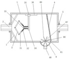
Fig. 1 is a schematic structural diagram of a filtering device for hydraulic engineering according to the present invention;
FIG. 2 is a schematic view of a buffer plate according to the present invention;
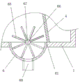
FIG. 3 is a schematic cross-sectional view of a semi-cylindrical housing portion of the present invention;
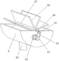
FIG. 4 is a schematic structural view of the whole of the semi-cylindrical housing, the plugging plate and the rotary stepping motor according to the present invention;
fig. 5 is a schematic cross-sectional structure view of the mounting post and the sliding sleeve of the present invention.
In the figure: the water filter comprises a filter shell 1, a water inlet pipe 2, a buffer plate 3, a rotating connecting rod 31, a movable sleeve rod 32, a mounting column 33, a mounting frame 34, a mounting seat 35, a mounting beam 36, a movable block 37, a first buffer spring 38, a sleeving groove 39, a first sliding block 310, a sliding sleeve 311, an extrusion plate 312, a second buffer spring 313, a second sliding block 314, a second sliding groove 315, a filter mesh sheet 4, a water outlet pipe 5, a semi-cylindrical shell 6, a garbage discharge hole 60, a mounting hole 61, a rotating stepping motor 62, a driving wheel 63, a chain belt 64, a driven wheel 65, a rotating shaft 66, a rotating cylinder 67, a blocking plate 68 and a water guide plate 7.
Detailed Description
The present invention will be further illustrated with reference to the following specific examples.
Examples
Referring to fig. 1-5, the embodiment provides a filtering apparatus for hydraulic engineering, including a filtering housing 1, a water inlet pipe 2 is fixedly disposed on the left side of the filtering housing 1, a water outlet pipe 5 is fixedly disposed on the right side of the filtering housing 1, a filter mesh sheet 4 is fixedly disposed on the right side inside the filtering housing 1, a vertically disposed mounting rack 34 is fixedly disposed on the inner wall of the top of the filtering housing 1, a horizontally disposed mounting column 33 is fixedly mounted at the bottom of the left side of the mounting rack 34, two obliquely disposed buffer plates 3 are disposed on the left side of the mounting column 33, the left ends of the two buffer plates 3 are rotatably hinged, the right ends of the two buffer plates 3 are respectively rotatably connected with a rotating connecting rod 31, a movable sleeve rod 32 is movably sleeved on the right end of the rotating connecting rod 31, a sliding sleeve 311 is slidably sleeved on the mounting column 33, and the right end of the movable sleeve rod 32 is rotatably hinged on the sliding sleeve 311, one end of the movable loop bar 32 close to the rotating connecting rod 31 is provided with a sleeving groove 39, one end of the rotating connecting rod 31 movably extends into the sleeving groove 39 and is fixedly connected with a movable block 37, and a first buffer spring 38 is fixedly sleeved between the movable block 37 and the inner wall of the right side of the sleeving groove 39;
the right end of the sliding sleeve 311 is fixedly connected with symmetrically arranged extrusion plates 312, and a second buffer spring 313 is fixedly connected between the right side of the extrusion plates 312 and the left side of the mounting frame 34;
the inner wall of the bottom of the adjacent filtering shell 1 positioned at the left side of the filtering net 4 is provided with a mounting opening 61, a semi-cylindrical shell 6 is fixedly sleeved in the mounting opening 61, and the bottom of the semi-cylindrical shell 6 is fixedly provided with a garbage discharge port 60, the semi-cylindrical shell 6 is rotatably provided with a rotating cylinder 67, the circumference of the rotating cylinder 67 is fixedly sleeved with a plurality of plugging plates 68, the blocking plates 68 are connected with the inner wall of the semi-cylindrical shell 6 in a sealing and sliding way, the garbage discharge port 60 is positioned between two adjacent blocking plates 68, the rotating cylinder 67 is fixedly sleeved with a rotating shaft 66, one end of the rotating shaft 66 rotatably penetrates to the outside of the rotating cylinder 67 and is fixedly sleeved with a driven wheel 65, one side of the semi-cylindrical shell 6 is fixedly provided with a rotary stepping motor 62, the output end of the rotary stepping motor 62 is fixedly sleeved with a driving wheel 63, and the driving wheel 63 is in transmission connection with a driven wheel 65 through a chain belt 64. The filtering device for the hydraulic engineering can greatly alleviate the impact force of water flow, further avoid the situation that the filter screen 4 is damaged due to overlarge impact force of the water flow, is beneficial to reducing the frequency of maintenance and replacement of the filter screen, can discharge the garbage filtered in the filtering shell 1 in time, avoids the defect that the garbage can be discharged only by stopping the machine and stopping water inlet in the prior art, realizes the function of discharging the filtered garbage without stopping the machine, greatly improves the filtering efficiency, and meets the use requirement of the existing filtering.
In this example, the number of the blocking plates 68 is specifically eight, and the eight blocking plates 68 are uniformly arranged on the circumference of the rotary cylinder 67 in a ring shape centering on the rotary shaft 66.
In this example, the edge of the blocking plate 68 is provided with a sliding sealing strip, and the edge of the blocking plate 68 is in sealing sliding connection with the inner wall of the semi-cylindrical shell 6 through the sliding sealing strip.
In this example, the top of the mounting bracket 34 is fixedly provided with a mounting seat 35, the top inner wall of the semi-cylindrical housing 6 is fixedly provided with a mounting beam 36, and the top of the mounting seat 35 is fixedly mounted at the bottom of the mounting beam 36.
In this example, the inner walls of the two sides of the sleeve groove 39 are provided with first sliding grooves, the two sides of the movable block 37 are provided with first sliding blocks 310, and the first sliding blocks 310 are slidably mounted in the first sliding grooves.
In this example, the inner wall of the sliding sleeve 311 is fixedly provided with symmetrically arranged second sliding blocks 314, the outer wall of the mounting post 33 is symmetrically provided with second sliding grooves 315, and the second sliding blocks 314 are slidably mounted in the second sliding grooves 315.
In this example, the left ends of the two buffer plates 3 are rotatably connected by the same hinge shaft.
In this example, the water guide plate 7 is symmetrically installed on the left inner wall of the filtering shell 1, and the water guide plate 7 is matched with the water inlet pipe 2.
In this example, the filter mesh sheet 4 is obliquely disposed inside the filter housing 1, and the bottom of the filter mesh sheet 4 is entirely obliquely disposed to the right.
According to the filtering device for the water conservancy project, when impurities and sundries in water are filtered in the water conservancy drainage process, running water flows into the filtering shell 1 from the water inlet pipe 2, and the buffer plate 3 is arranged, so that the buffer plate 3 can buffer overlarge impact force of the water flow, damage to the filter mesh 4 due to the overlarge impact force of the water flow is prevented, and the maintenance and replacement frequency of the filter mesh 4 is increased; specifically, when the buffer plates 3 are subjected to an excessive water flow impact force, the two buffer plates 3 can rotate to approach each other, and when the two buffer plates 3 rotate to approach each other, the two buffer plates also rotate with the rotating connecting rod 31 and enable the rotating connecting rod 31 and the movable block 37 to compress the first buffer spring 38 inside the movable loop bar 32, so that a part of the excessive impact force can be consumed through the compression deformation of the first buffer spring 38; meanwhile, the two buffer plates 3 are enabled to integrally buffer and move rightwards, and when moving rightwards, the two buffer plates 3 also drive the rotating connecting rod 31, the movable loop bar 32 and the extrusion plate 312 to integrally move rightwards and compress and buffer the second buffer spring 313, so that a part of overlarge impact force can be further consumed through the deformation of the second buffer spring 313; finally, the impact force of water flow can be greatly alleviated, the situation that the filter screen 4 is damaged due to overlarge impact force of the water flow can be avoided, and the frequency of filter screen maintenance and replacement can be reduced;
in this example, since the filter mesh 4 is obliquely arranged, after the filter mesh 4 is filtered, the filtered trash can fall between two adjacent plugging plates 68 in the semi-cylindrical shell 6, then the output end of the rotary stepping motor 62 is utilized to drive the driving wheel 63 to rotate counterclockwise, the driving wheel 63 drives the driven wheel 65 to rotate counterclockwise through the chain belt 64 when rotating, and the driven wheel 65 drives the rotating shaft 66, the rotating cylinder 67 and the plugging plates 68 to rotate counterclockwise when rotating, so that the trash can be brought into the semi-cylindrical shell 6 counterclockwise through the counterclockwise rotation of the plugging plates 68, and the trash can be discharged from the trash discharge port 60 at the bottom of the semi-cylindrical shell 6; can carry out timely discharge with the inside rubbish that filters of filter housing 1 like this, avoid still need shut down in the past, stop into water and just can be with rubbish exhaust drawback to make filtration efficiency improve greatly, satisfied the filterable user demand of current hydraulic engineering.
The above description is only for the preferred embodiment of the present invention, but the scope of the present invention is not limited thereto, and any person skilled in the art should be considered to be within the technical scope of the present invention, and the technical solutions and the inventive concepts thereof according to the present invention should be equivalent or changed within the scope of the present invention.
Claims (9)
1. A filter device for hydraulic engineering comprises a filter shell (1), wherein a water inlet pipe (2) is fixedly arranged on the left side of the filter shell (1), a water outlet pipe (5) is fixedly arranged on the right side of the filter shell (1), and a filter screen (4) is fixedly arranged on the right side inside the filter shell (1), and is characterized in that a vertically arranged mounting rack (34) is fixedly arranged on the inner wall of the top of the filter shell (1), a horizontally arranged mounting column (33) is fixedly arranged at the bottom of the left side of the mounting rack (34), two obliquely arranged buffer plates (3) are arranged on the left side of the mounting column (33), the left ends of the two buffer plates (3) are rotatably hinged, the right ends of the two buffer plates (3) are respectively rotatably connected with a rotating connecting rod (31), a movable sleeve rod (32) is movably sleeved at the right end of the rotating connecting rod (31), a sliding sleeve (311) is slidably sleeved on the mounting column (33), the right end of the movable loop bar (32) is rotatably hinged to the sliding sleeve (311), a sleeving groove (39) is formed in one end, close to the rotating connecting rod (31), of the movable loop bar (32), one end of the rotating connecting rod (31) movably extends into the sleeving groove (39) and is fixedly connected with a movable block (37), and a first buffer spring (38) is fixedly sleeved between the movable block (37) and the inner wall of the right side of the sleeving groove (39);
the right end of the sliding sleeve (311) is fixedly connected with symmetrically arranged extrusion plates (312), and a second buffer spring (313) is fixedly connected between the right side of the extrusion plate (312) and the left side of the mounting rack (34);
be located and be equipped with installing port (61) on the bottom inner wall of filter shell (1) that filter screen piece (4) left side is adjacent, fixed cover has connect semicylindrical shell (6) in installing port (61), and the fixed rubbish discharge gate (60) that is provided with in bottom of semicylindrical shell (6), a rotary drum (67) is installed to semicylindrical shell (6) internal rotation, and fixed cover has connect a plurality of closure plates (68) on the circumference of rotary drum (67), and the inner wall sealing sliding connection of closure plate (68) and semicylindrical shell (6), rubbish discharge gate (60) are located between two adjacent closure plates (68), fixed cover has been connected pivot (66) in rotary drum (67), and the one end of pivot (66) rotates and runs through to the outside of rotary drum (67) and fixed cover has been connected from driving wheel (65), one side fixed mounting of semicylindrical shell (6) has rotatory step motor (62), the output end of the rotating stepping motor (62) is fixedly sleeved with a driving wheel (63), and the driving wheel (63) is in transmission connection with a driven wheel (65) through a chain belt (64).
2. The filtering device for the water conservancy project according to claim 1, wherein the number of the blocking plates (68) is specifically eight, and the eight blocking plates (68) are uniformly arranged on the circumference of the rotating cylinder (67) in an annular shape based on the rotating shaft (66) as a center.
3. A filter equipment for hydraulic engineering according to claim 1, characterized in that the edge of the closure plate (68) is provided with a sliding seal strip, and the edge of the closure plate (68) is in sealing sliding connection with the inner wall of the semi-cylindrical housing (6) through the sliding seal strip.
4. The filtering device for the water conservancy project according to claim 1, wherein a mounting seat (35) is fixedly arranged at the top of the mounting frame (34), a mounting beam (36) is fixedly arranged on the inner wall of the top of the semi-cylindrical shell (6), and the top of the mounting seat (35) is fixedly arranged at the bottom of the mounting beam (36).
5. The filtering device for the water conservancy project according to claim 1, wherein the inner walls of the two sides of the sleeving groove (39) are respectively provided with a first sliding groove, the two sides of the movable block (37) are respectively provided with a first sliding block (310), and the first sliding blocks (310) are slidably arranged in the first sliding grooves.
6. The filtering device for the water conservancy project according to claim 1, wherein the inner wall of the sliding sleeve (311) is fixedly provided with symmetrically arranged second sliding blocks (314), the outer wall of the mounting column (33) is symmetrically provided with second sliding grooves (315), and the second sliding blocks (314) are slidably mounted in the second sliding grooves (315).
7. A filtering device for hydraulic engineering according to claim 1, characterized in that the left ends of the two damping plates (3) are pivotally connected by a common hinge.
8. The filtering device for the water conservancy project according to claim 1, wherein the water guide plates (7) which are obliquely arranged are symmetrically arranged on the inner wall of the left side of the filtering shell (1), and the water guide plates (7) are matched with the water inlet pipe (2).
9. A filter equipment for hydraulic engineering according to claim 1, characterized in that the filter screen (4) is arranged obliquely inside the filter housing (1), and the bottom of the filter screen (4) is arranged obliquely to the right.
Priority Applications (1)
| Application Number | Priority Date | Filing Date | Title |
|---|---|---|---|
| CN202110504492.8A CN113134257A (en) | 2021-05-10 | 2021-05-10 | Filter equipment that hydraulic engineering used |
Applications Claiming Priority (1)
| Application Number | Priority Date | Filing Date | Title |
|---|---|---|---|
| CN202110504492.8A CN113134257A (en) | 2021-05-10 | 2021-05-10 | Filter equipment that hydraulic engineering used |
Publications (1)
| Publication Number | Publication Date |
|---|---|
| CN113134257A true CN113134257A (en) | 2021-07-20 |
Family
ID=76817992
Family Applications (1)
| Application Number | Title | Priority Date | Filing Date |
|---|---|---|---|
| CN202110504492.8A Withdrawn CN113134257A (en) | 2021-05-10 | 2021-05-10 | Filter equipment that hydraulic engineering used |
Country Status (1)
| Country | Link |
|---|---|
| CN (1) | CN113134257A (en) |
Cited By (1)
| Publication number | Priority date | Publication date | Assignee | Title |
|---|---|---|---|---|
| CN114016572A (en) * | 2021-10-29 | 2022-02-08 | 国能龙源环保有限公司 | Low-pressure automatic compensation device for industrial water and process water of desulfurization system and modification method |
-
2021
- 2021-05-10 CN CN202110504492.8A patent/CN113134257A/en not_active Withdrawn
Cited By (1)
| Publication number | Priority date | Publication date | Assignee | Title |
|---|---|---|---|---|
| CN114016572A (en) * | 2021-10-29 | 2022-02-08 | 国能龙源环保有限公司 | Low-pressure automatic compensation device for industrial water and process water of desulfurization system and modification method |
Similar Documents
| Publication | Publication Date | Title |
|---|---|---|
| CN211328402U (en) | Filter belt cleaning device for sewage treatment | |
| CN113134257A (en) | Filter equipment that hydraulic engineering used | |
| CN213537684U (en) | Municipal sludge treatment device with solid-liquid separation function | |
| CN113389908A (en) | Device and method for cleaning garbage in valve | |
| CN212369679U (en) | Self-cleaning Y-shaped filter | |
| CN111957129A (en) | Automobile filter capable of preventing dust accumulation | |
| CN111851446A (en) | River pollution multilayer treatment system | |
| CN217015529U (en) | Blow-off pipe with sundry blocking function | |
| CN115045063B (en) | Intelligent textile raw material edulcoration cleaning device | |
| CN114482250B (en) | Integrated pump station for polymer concrete shaft | |
| CN218264255U (en) | Rain and sewage flow distribution pipe net structure | |
| CN218076792U (en) | Prevent filtering conduit of jam | |
| CN216738013U (en) | Dredged sludge rapid dewatering device | |
| CN213555724U (en) | Filter equipment is used in emollient production | |
| CN220566667U (en) | Novel waterproof dustproof high-performance valve transmission mechanism | |
| CN212236457U (en) | Automobile filter capable of preventing dust accumulation | |
| CN219157589U (en) | Hydraulic engineering gate device | |
| CN220302087U (en) | Bridge pile foundation construction drill slag mud-water separation processing apparatus | |
| CN213891388U (en) | Intelligent oil expression all-in-one machine | |
| CN214613303U (en) | A paper pulp filter equipment for inside pulp pond | |
| CN219975387U (en) | PPS airtight electric valve | |
| CN214944185U (en) | Novel shunting oil screen pipe | |
| CN219139984U (en) | Forged steel gate valve | |
| CN215214767U (en) | Prevent electric flange butterfly valve of jam | |
| CN218934257U (en) | Antiseep aluminium alloy door and window |
Legal Events
| Date | Code | Title | Description |
|---|---|---|---|
| PB01 | Publication | ||
| PB01 | Publication | ||
| SE01 | Entry into force of request for substantive examination | ||
| SE01 | Entry into force of request for substantive examination | ||
| WW01 | Invention patent application withdrawn after publication | ||
| WW01 | Invention patent application withdrawn after publication |
Application publication date: 20210720 |