CN113131662A - Integrated integrated permanent magnet synchronous traction motor - Google Patents
Integrated integrated permanent magnet synchronous traction motor Download PDFInfo
- Publication number
- CN113131662A CN113131662A CN202110287696.0A CN202110287696A CN113131662A CN 113131662 A CN113131662 A CN 113131662A CN 202110287696 A CN202110287696 A CN 202110287696A CN 113131662 A CN113131662 A CN 113131662A
- Authority
- CN
- China
- Prior art keywords
- permanent magnet
- heat dissipation
- shell
- traction motor
- magnet synchronous
- Prior art date
- Legal status (The legal status is an assumption and is not a legal conclusion. Google has not performed a legal analysis and makes no representation as to the accuracy of the status listed.)
- Pending
Links
- 230000001360 synchronised effect Effects 0.000 title claims abstract description 27
- 230000017525 heat dissipation Effects 0.000 claims abstract description 53
- 230000007246 mechanism Effects 0.000 claims abstract description 25
- 230000001681 protective effect Effects 0.000 claims abstract description 23
- 238000013016 damping Methods 0.000 claims abstract description 22
- 230000005389 magnetism Effects 0.000 claims abstract description 10
- 230000001105 regulatory effect Effects 0.000 claims description 34
- 238000000576 coating method Methods 0.000 claims description 22
- 239000011248 coating agent Substances 0.000 claims description 21
- 230000000694 effects Effects 0.000 claims description 12
- 238000003825 pressing Methods 0.000 claims description 12
- 238000009826 distribution Methods 0.000 claims description 10
- 230000035939 shock Effects 0.000 claims description 10
- 238000010521 absorption reaction Methods 0.000 claims description 6
- 238000004891 communication Methods 0.000 claims description 6
- 230000002209 hydrophobic effect Effects 0.000 claims description 4
- 239000000463 material Substances 0.000 claims description 4
- 238000001746 injection moulding Methods 0.000 claims description 3
- 238000003466 welding Methods 0.000 claims description 3
- 210000002268 wool Anatomy 0.000 claims description 3
- 238000005253 cladding Methods 0.000 description 4
- XLYOFNOQVPJJNP-UHFFFAOYSA-N water Substances O XLYOFNOQVPJJNP-UHFFFAOYSA-N 0.000 description 3
- 238000010586 diagram Methods 0.000 description 2
- 238000009434 installation Methods 0.000 description 2
- 230000009286 beneficial effect Effects 0.000 description 1
- 238000006243 chemical reaction Methods 0.000 description 1
- 230000006835 compression Effects 0.000 description 1
- 238000007906 compression Methods 0.000 description 1
- 230000007547 defect Effects 0.000 description 1
- 238000007599 discharging Methods 0.000 description 1
- 238000001035 drying Methods 0.000 description 1
- 239000000428 dust Substances 0.000 description 1
- 238000005516 engineering process Methods 0.000 description 1
- 238000010030 laminating Methods 0.000 description 1
- 238000004519 manufacturing process Methods 0.000 description 1
- 210000003205 muscle Anatomy 0.000 description 1
- 238000013021 overheating Methods 0.000 description 1
- 239000000243 solution Substances 0.000 description 1
Images


Classifications
-
- H—ELECTRICITY
- H02—GENERATION; CONVERSION OR DISTRIBUTION OF ELECTRIC POWER
- H02K—DYNAMO-ELECTRIC MACHINES
- H02K5/00—Casings; Enclosures; Supports
- H02K5/24—Casings; Enclosures; Supports specially adapted for suppression or reduction of noise or vibrations
-
- H—ELECTRICITY
- H02—GENERATION; CONVERSION OR DISTRIBUTION OF ELECTRIC POWER
- H02K—DYNAMO-ELECTRIC MACHINES
- H02K5/00—Casings; Enclosures; Supports
- H02K5/04—Casings or enclosures characterised by the shape, form or construction thereof
- H02K5/10—Casings or enclosures characterised by the shape, form or construction thereof with arrangements for protection from ingress, e.g. water or fingers
-
- H—ELECTRICITY
- H02—GENERATION; CONVERSION OR DISTRIBUTION OF ELECTRIC POWER
- H02K—DYNAMO-ELECTRIC MACHINES
- H02K5/00—Casings; Enclosures; Supports
- H02K5/04—Casings or enclosures characterised by the shape, form or construction thereof
- H02K5/20—Casings or enclosures characterised by the shape, form or construction thereof with channels or ducts for flow of cooling medium
-
- H—ELECTRICITY
- H02—GENERATION; CONVERSION OR DISTRIBUTION OF ELECTRIC POWER
- H02K—DYNAMO-ELECTRIC MACHINES
- H02K9/00—Arrangements for cooling or ventilating
- H02K9/02—Arrangements for cooling or ventilating by ambient air flowing through the machine
Abstract
The invention discloses an integrated permanent magnet synchronous traction motor, relates to the technical field of permanent magnet synchronous traction motors, and solves the problems that internal heat cannot be timely dissipated when equipment runs, the running of the equipment is influenced, internal components vibrate greatly, and the output power of the equipment is influenced due to the fact that a machine body of the permanent magnet synchronous traction motor is excessively sealed due to the technical requirements of the equipment. The utility model provides an integrated integral type permanent magnetism synchronous traction motor, includes outside protective housing, the one end terminal surface of outside protective housing is provided with the front end housing, two unable adjustment bases are evenly installed to the below of outside protective housing, the inboard bottom surface fixed mounting of outside protective housing has the mount pad, the inside of mount pad is provided with supplementary heat dissipation mechanism. The heat dissipation device can quickly dissipate heat generated when the equipment runs through the heat dissipation mechanism, the auxiliary heat dissipation mechanism and the damping mechanism, so that the equipment is prevented from being overheated, and the vibration of internal components of the equipment during running can be reduced.
Description
Technical Field
The invention relates to the technical field of permanent magnet synchronous traction motors, in particular to an integrated permanent magnet synchronous traction motor.
Background
With the rapid development of social economy, a traction system of a permanent magnet synchronous motor is a power system of a train and consists of a converter and a motor, wherein the converter is equivalent to the heart of the train, the motor is better than the muscle of the train, the motor is mainly responsible for transmitting power, the conversion from electric energy to mechanical energy is completed, the train is driven to run stably, and the power key in the permanent magnet synchronous traction motor is realized during the permanent magnet synchronous traction of the motor.
However, the existing permanent magnet synchronous traction motor has the defects that the machine body is too sealed due to the technical requirements of equipment, so that internal heat cannot be timely dissipated when the equipment runs, the running of the equipment is influenced, and the output power of the equipment is influenced due to large vibration of internal components; therefore, the existing requirements are not met, and an integrated permanent magnet synchronous traction motor is provided for the requirements.
Disclosure of Invention
The invention aims to provide an integrated permanent magnet synchronous traction motor, which aims to solve the problems that the permanent magnet synchronous traction motor provided in the background technology has an excessively sealed machine body due to the technical requirements of equipment, so that internal heat cannot be timely dissipated when the equipment runs, the running of the equipment is influenced, the vibration of internal components is large, the output power of the equipment is influenced, and the like.
In order to achieve the purpose, the invention provides the following technical scheme: an integrated permanent magnet synchronous traction motor comprises an external protective shell, wherein a front end cover is arranged on one end face of the external protective shell, two fixed bases are uniformly arranged below the external protective shell, a mounting seat is fixedly arranged on the inner bottom face of the external protective shell, an auxiliary heat dissipation mechanism is arranged inside the mounting seat, the auxiliary heat dissipation mechanism comprises a flow collection groove, a plurality of bottom air outlet holes are uniformly formed in two sides of the flow collection groove, a plurality of communication air holes are uniformly formed below the flow collection groove, and the communication air holes penetrate through the bottom face of the external protective shell and are communicated with the outside;
an internal component coating shell is mounted on the surface of the mounting seat, an output rotating shaft penetrates through one end of the internal component coating shell, the end part of the output rotating shaft penetrates through the middle wool of the front end cover and extends to the outside, a heat dissipation shell covers the outer side of the internal component coating shell, a plurality of damping mechanisms are arranged on the upper surface and two sides of the heat dissipation shell, and a heat dissipation mechanism is arranged above the heat dissipation shell;
the heat dissipation mechanism comprises a plurality of heat dissipation air grooves which are uniformly distributed inside the external protection shell, a distribution air channel is arranged above the heat dissipation air grooves, an air inlet is arranged above one end of the distribution air channel, an air inlet end cover is arranged above the air inlet, and the air inlet end cover is fixed on the surface of the external protection shell.
Preferably, damper includes the shock attenuation clamp plate, the even fixed a plurality of reference column that is provided with in surface, the outside cover of reference column has the pressure regulating spring, the one end activity of pressure regulating spring is provided with movable pressure regulating plate, a side surface of activity pressure regulating plate is evenly inlayed and is provided with two permanent magnets, the opposite side of permanent magnet is provided with the electro-magnet.
Preferably, a plurality of flow guide grooves are uniformly formed in the surface of the heat dissipation shell, and a hydrophobic coating is coated on the inner sides of the flow guide grooves.
Preferably, the surface of the air inlet end cover is movably provided with a breathable dustproof cover plate, and the bottom end of the breathable dustproof cover plate is positioned and inserted at the inner side of the top end of the air inlet end cover through a clamping groove.
Preferably, the calibers of the end parts of the two ends of the bottom air outlet hole are different, and the calibers of the end parts of the bottom air outlet hole, which are positioned in the mounting seat, are larger.
Preferably, the four end corners of the front end cover are uniformly provided with a plurality of positioning holes, and the front end cover passes through the positioning holes through screws to be fixed with the end part of the external protective shell.
Preferably, the surface of the fixed base is completely attached to the bottom end surface of the external protection shell, and the fixed base is fixed to the external protection shell through welding.
Preferably, one end of the positioning column penetrates through the inside of the movable pressure regulating plate, and the contact surfaces between the movable pressure regulating plate and the positioning column are completely smooth.
Preferably, the end face of one end of the positioning column is completely attached to the surface of the damping pressing plate, the positioning column and the damping pressing plate are integrally formed by injection molding, and the positioning column and the damping pressing plate are made of uniform plastic materials.
Preferably, the end face of one end of the positioning column is completely attached to the surface of the damping pressing plate, the positioning column and the damping pressing plate are integrally formed by injection molding, and the positioning column and the damping pressing plate are made of uniform plastic materials.
Compared with the prior art, the invention has the beneficial effects that:
1. when the equipment runs, external cold air enters the air inlet along the breathable dustproof cover plate on the surface of the air inlet end cover and fills the whole distribution air passage, then the cold air is blown to the surface of the radiating shell on the outer side of the inner component coating shell along the radiating air grooves communicated with the lower part of the distribution air passage, at the moment, the cold air can uniformly adhere to the surface of the radiating shell due to the guide grooves uniformly distributed on the outer side of the radiating shell, can effectively take away heat absorbed by the radiating shell and generated by the inner component coating shell inner component, then enters the collecting groove along the bottom air outlet holes uniformly distributed on the two sides of the mounting seat and is finally emitted to the outside along the communicating air holes, the inside of the equipment can be effectively radiated, the internal overheating of the equipment is avoided, the safe and stable running of the equipment is ensured, and the condensed water formed on the surface of the radiating shell while the cold air is radiated can be distributed along the communicating air holes by the guide grooves Discharging to the outside to ensure the drying of the inside of the equipment;
2. when the equipment is powered on and operates, the power supply of the electromagnet is powered on step by step, the electromagnet is powered on and then adds magnetism which is completely mutually exclusive with the surface magnetism of the permanent magnet, the permanent magnet generates different reasoning, so that the permanent magnet drives the movable pressure regulating plate to slide along the outer side of the positioning column, the damping pressure plate attached to the outer surface of the heat dissipation shell is close to the damping pressure plate, the movable pressure regulating plate compresses the pressure regulating spring, the pressure regulating spring is passively compressed and then transmits a force to the damping pressure plate to coat the center of the shell to an internal component, the damping pressure plate presses the heat dissipation shell and the internal component coating shell, the damping pressure plates on the upper surface and two sides of the heat dissipation shell outside the internal component coating shell synchronously press, and the straightening can be effectively weakened to avoid the internal component coating shell from generating vibration when the, the stable operation of the equipment is ensured by reducing the vibration of the internal components of the equipment, and the unnecessary loss generated by the vibration in the equipment is reduced.
Drawings
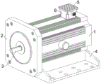
FIG. 1 is a schematic structural view of the present invention as a whole;
FIG. 2 is a partial structural view of the present invention as a whole;
FIG. 3 is a cross-sectional view of the outer protective shell of the present invention;
FIG. 4 is a schematic structural diagram of a heat dissipation mechanism according to the present invention;
FIG. 5 is a schematic structural view of the shock absorbing mechanism of the present invention;
fig. 6 is a schematic structural diagram of the heat dissipation housing of the present invention.
In the figure: 1. an outer protective housing; 2. a front end cover; 3. an output shaft; 4. a fixed base; 5. a breathable dustproof cover plate; 6. a heat dissipation mechanism; 601. an air inlet end cover; 602. an air inlet; 603. distributing the air passages; 604. a heat dissipation air tank; 7. the inner component covers the shell; 8. an auxiliary heat dissipation mechanism; 801. a bottom vent hole; 802. a collecting groove; 803. the air holes are communicated; 9. a damping mechanism; 901. a damping pressure plate; 902. a positioning column; 903. a pressure regulating spring; 904. a movable pressure regulating plate; 905. a permanent magnet; 906. an electromagnet; 10. a heat dissipating housing; 11. a diversion trench; 12. and (7) mounting a seat.
Detailed Description
The technical solutions in the embodiments of the present invention will be clearly and completely described below with reference to the drawings in the embodiments of the present invention, and it is obvious that the described embodiments are only a part of the embodiments of the present invention, and not all of the embodiments.
Referring to fig. 1 to 6, an embodiment of the present invention includes: an integrated permanent magnet synchronous traction motor comprises an external protection shell 1, wherein a front end cover 2 is arranged on one end face of the external protection shell 1, two fixing bases 4 are uniformly arranged below the external protection shell 1, a mounting seat 12 is fixedly arranged on the inner bottom face of the external protection shell 1, an auxiliary heat dissipation mechanism 8 is arranged inside the mounting seat 12, the auxiliary heat dissipation mechanism 8 comprises a flow collecting groove 802, a plurality of bottom air outlet holes 801 are uniformly formed in two sides of the flow collecting groove 802, a plurality of communication air holes 803 are uniformly formed below the flow collecting groove 802, and the communication air holes 803 communicate with the outside through the bottom face of the external protection shell 1;
an internal component coating shell 7 is mounted on the surface of the mounting seat 12, an output rotating shaft 3 penetrates through one end of the internal component coating shell 7, the end part of the output rotating shaft 3 penetrates through the middle wool of the front end cover 2 and extends to the outside, a heat dissipation shell 10 covers the outer side of the internal component coating shell 7, a plurality of damping mechanisms 9 are arranged on the upper surface and two sides of the heat dissipation shell 10, and a heat dissipation mechanism 6 is arranged above the heat dissipation shell 10;
the heat dissipation mechanism 6 includes a plurality of heat dissipation air grooves 604 uniformly distributed inside the external protective housing 1, a distribution air passage 603 is provided above the heat dissipation air grooves 604, an air inlet 602 is provided above one end of the distribution air passage 603, an air inlet end cover 601 is provided above the air inlet 602, and the air inlet end cover 601 is fixed on the surface of the external protective housing 1.
Further, damper 9 includes shock attenuation clamp plate 901, the surface is even fixed and is provided with a plurality of reference column 902, the outside cover of reference column 902 has pressure regulating spring 903, the one end activity of pressure regulating spring 903 is provided with movable pressure regulating plate 904, a side surface of movable pressure regulating plate 904 is evenly inlayed and is provided with two permanent magnets 905, the opposite side of permanent magnet 905 is provided with electro-magnet 906, can apply the power to internal component cladding casing 7 center department to internal component cladding casing 7, reduce 7 internal component of internal component cladding casing 7 holistic vibrations of internal component cladding casing 7 when moving, guarantee that equipment operation is stable.
Further, the surface of heat dissipation casing 10 evenly is provided with a plurality of guiding gutter 11, and the hydrophobic coating has been paintd to the inboard of guiding gutter 11, and guiding gutter 11 that the hydrophobic coating was paintd on the surface can be with the cold air that transmits to heat dissipation casing 10 surface carry out laminating heat dissipation casing 10 surface homodisperse, and avoid the cold air to meet the comdenstion water that the heat formed and adhere to.
Further, the surface activity of air inlet end cover 601 is provided with ventilative dustproof cover plate 5, and the bottom of ventilative dustproof cover plate 5 is passed through the draw-in groove location and is pegged graft at the top of air inlet end cover 601 inboardly, and ventilative dustproof cover plate 5 can guarantee that external cold air passes through the middle entering equipment radiating in air inlet end cover 601, intercepts the dust in the air, avoids equipment inside to receive the pollution.
Further, the end calibers of the two ends of the bottom air outlet hole 801 are not consistent, the end calibers of the bottom air outlet hole 801 located inside the mounting seat 12 are larger, the positioning holes facilitate the corresponding positioning of the front end cover 2 and the end face of the external protection shell 1 during the installation, the front end cover 2 and the external protection shell 1 are convenient to fix, and the external protection shell 1 is prevented from falling off.
Further, four end angle departments of front end housing 2 all evenly are provided with a plurality of locating hole, and front end housing 2 passes the end fixing of locating hole and outside protective housing 1 through the screw, and the locating hole makes things convenient for front end housing 2 to correspond the location with outside protective housing 1's terminal surface when the installation, makes things convenient for front end housing 2 to fix with outside protective housing 1, avoids outside protective housing 1 to drop.
Further, unable adjustment base 4's surface and the bottom surface of outside protective housing 1 laminate completely, unable adjustment base 4 and outside protective housing 1 pass through welded fastening, and the welding has strengthened unable adjustment base 4 and outside protective housing 1's connection performance and stability ability, has fine mechanical strength, guarantees the stability behind the equipment unit mount.
Further, the inside of activity pressure regulating board 904 is run through to the one end of reference column 902, and the mutual contact surface between activity pressure regulating board 904 and the reference column 902 is all smooth completely, and the resistance that completely smooth contact surface received when activity pressure regulating board 904 slides is less, guarantees that activity pressure regulating board 904 can the maximum compression to pressure regulating spring 903.
Further, the magnetism attached to the electromagnet 906 after the electromagnet is electrified is completely opposite to the magnetism of the surface of the permanent magnet 905 corresponding to the electromagnet, the electromagnet 906 is magnetically connected with the permanent magnet 905, and the opposite magnetism enables the electromagnet 906 to generate repulsive force to the permanent magnet 905 after the electromagnet is electrified, so that the movable pressure regulating plate 904 is pushed to slide along the positioning column 902 to compress the pressure regulating spring 903.
Further, the end face of one end of the positioning column 902 is completely attached to the surface of the shock absorption pressing plate 901, the positioning column 902 and the shock absorption pressing plate 901 are integrally injection-molded, the positioning column 902 and the shock absorption pressing plate 901 are made of uniform plastic materials, the integrally injection-molded parts are stably connected, the mechanical strength is high, and the manufacturing is convenient and the cost is low.
The working principle is as follows: when the device is used, when the device is powered on and operates, the power supply of the electromagnet 906 is powered on step by step, at the moment, the electromagnet 906 is powered on and then can be added with magnetism completely exclusive to the surface magnetism of the permanent magnet 905, the permanent magnet 905 is inferred in different ways, so that the permanent magnet 905 drives the movable pressure regulating plate 904 to slide along the outer side of the positioning column 902, the damping pressure plate 901 attached to the outer surface of the heat dissipation shell 10 is close to, the movable pressure regulating plate 904 compresses the pressure regulating spring 903, at the moment, the pressure regulating spring 903 is passively compressed and then can transmit force to the damping pressure regulating plate 901 to cover the center of the shell 7 for internal components, the damping pressure plate 901 presses the heat dissipation shell 10 and the internal component coating shell 7, at the moment, the upper surface of the heat dissipation shell 10 outside the internal component coating shell 7 and the damping pressure plates 901 on the two sides are synchronously pressed, and the straightening, the stable operation of the equipment is ensured by reducing the vibration of the internal components of the equipment, and the unnecessary loss generated by the vibration in the equipment is reduced, when the equipment is in operation, the external cold air enters the air inlet 602 along the air-permeable dustproof cover plate 5 on the surface of the air inlet end cover 601, fills the whole distribution air passage 603, then blows to the surface of the heat dissipation shell 10 on the outer side of the internal component coating shell 7 along the heat dissipation air groove 604 communicated below the distribution air passage 603, at the moment, the cold air flows by uniformly adhering to the surface of the heat dissipation shell 10 through the flow guide grooves 11 uniformly distributed on the outer side of the heat dissipation shell 10, can effectively take away the heat generated by the internal components of the internal component coating shell 7 absorbed by the heat dissipation shell 10, then enters the flow collecting groove 802 along the bottom air outlet holes 801 uniformly distributed on the two sides of the mounting seat 12, and finally is, can effectually dispel the heat to equipment inside, avoid equipment inside overheated, guarantee equipment safety, stable operation, and can discharge the comdenstion water that cold air formed on heat dissipation shell 10 surface in the radiating through guiding gutter 11, bottom venthole 801, mass flow groove 802 and intercommunication gas pocket 803, guarantee the inside dry of equipment.
Claims (10)
1. An integrated permanent magnet synchronous traction motor comprises an external protective shell (1), and is characterized in that: a front end cover (2) is arranged on one end face of the external protection shell (1), two fixing bases (4) are uniformly arranged below the external protection shell (1), a mounting seat (12) is fixedly arranged on the inner bottom face of the external protection shell (1), an auxiliary heat dissipation mechanism (8) is arranged inside the mounting seat (12), the auxiliary heat dissipation mechanism (8) comprises a flow collection groove (802), a plurality of bottom air outlets (801) are uniformly formed in two sides of the flow collection groove (802), a plurality of communication air holes (803) are uniformly formed below the flow collection groove (802), and the communication air holes (803) penetrate through the bottom face of the external protection shell (1) and are communicated with the outside;
an internal component coating shell (7) is mounted on the surface of the mounting seat (12), an output rotating shaft (3) penetrates through one end of the internal component coating shell (7), the end portion of the output rotating shaft (3) penetrates through the middle wool of the front end cover (2) and extends to the outside, a heat dissipation shell (10) covers the outer side of the internal component coating shell (7), a plurality of damping mechanisms (9) are arranged on the upper surface and two sides of the heat dissipation shell (10), and a heat dissipation mechanism (6) is arranged above the heat dissipation shell (10);
the heat dissipation mechanism (6) comprises a plurality of heat dissipation air grooves (604) which are uniformly distributed inside the external protection shell (1), air distribution channels (603) are arranged above the heat dissipation air grooves (604), air inlets (602) are arranged above one ends of the air distribution channels (603), air inlet end covers (601) are arranged above the air inlets (602), and the air inlet end covers (601) are fixed on the surface of the external protection shell (1).
2. The integrated permanent magnet synchronous traction motor according to claim 1, wherein: damping mechanism (9) are including shock attenuation clamp plate (901), the surface uniform fixation is provided with a plurality of reference column (902), the outside cover of reference column (902) has pressure regulating spring (903), the one end activity of pressure regulating spring (903) is provided with activity pressure regulating plate (904), a side surface of activity pressure regulating plate (904) is evenly inlayed and is provided with two permanent magnets (905), the opposite side of permanent magnet (905) is provided with electro-magnet (906).
3. The integrated permanent magnet synchronous traction motor according to claim 1, wherein: the surface of the heat dissipation shell (10) is uniformly provided with a plurality of guide grooves (11), and the inner sides of the guide grooves (11) are coated with hydrophobic coatings.
4. The integrated permanent magnet synchronous traction motor according to claim 1, wherein: the surface activity of air inlet end cover (601) is provided with ventilative dustproof apron (5), the bottom of ventilative dustproof apron (5) is passed through the draw-in groove location and is pegged graft at the top inboard of air inlet end cover (601).
5. The integrated permanent magnet synchronous traction motor according to claim 1, wherein: the calibers of the end parts of the two ends of the bottom air outlet hole (801) are different, and the calibers of the end parts of the bottom air outlet hole (801) positioned in the mounting base (12) are larger.
6. The integrated permanent magnet synchronous traction motor according to claim 1, wherein: the four end corners of the front end cover (2) are uniformly provided with a plurality of positioning holes, and the front end cover (2) penetrates through the positioning holes through screws to be fixed with the end part of the external protective shell (1).
7. The integrated permanent magnet synchronous traction motor according to claim 1, wherein: the surface of the fixed base (4) is completely attached to the bottom end surface of the external protection shell (1), and the fixed base (4) is fixed with the external protection shell (1) through welding.
8. The integrated permanent magnet synchronous traction motor according to claim 2, wherein: one end of the positioning column (902) penetrates through the inside of the movable pressure regulating plate (904), and the contact surfaces of the movable pressure regulating plate (904) and the positioning column (902) are completely smooth.
9. The integrated permanent magnet synchronous traction motor according to claim 2, wherein: the added magnetism of the electromagnet (906) after being electrified is completely opposite to the magnetism of the surface of the permanent magnet (905) corresponding to the electromagnet, and the electromagnet (906) is magnetically connected with the permanent magnet (905).
10. The integrated permanent magnet synchronous traction motor according to claim 2, wherein: the end face of one end of the positioning column (902) is completely attached to the surface of the shock absorption pressing plate (901), the positioning column (902) and the shock absorption pressing plate (901) are integrally formed by injection molding, and the positioning column (902) and the shock absorption pressing plate (901) are made of uniform plastic materials.
Priority Applications (1)
| Application Number | Priority Date | Filing Date | Title |
|---|---|---|---|
| CN202110287696.0A CN113131662A (en) | 2021-03-17 | 2021-03-17 | Integrated integrated permanent magnet synchronous traction motor |
Applications Claiming Priority (1)
| Application Number | Priority Date | Filing Date | Title |
|---|---|---|---|
| CN202110287696.0A CN113131662A (en) | 2021-03-17 | 2021-03-17 | Integrated integrated permanent magnet synchronous traction motor |
Publications (1)
| Publication Number | Publication Date |
|---|---|
| CN113131662A true CN113131662A (en) | 2021-07-16 |
Family
ID=76773490
Family Applications (1)
| Application Number | Title | Priority Date | Filing Date |
|---|---|---|---|
| CN202110287696.0A Pending CN113131662A (en) | 2021-03-17 | 2021-03-17 | Integrated integrated permanent magnet synchronous traction motor |
Country Status (1)
| Country | Link |
|---|---|
| CN (1) | CN113131662A (en) |
Cited By (1)
| Publication number | Priority date | Publication date | Assignee | Title |
|---|---|---|---|---|
| CN113964997A (en) * | 2021-11-04 | 2022-01-21 | 江苏锐生祥电气智能科技有限公司 | Eddy current starting three-phase rare earth permanent magnet synchronous motor |
Citations (9)
| Publication number | Priority date | Publication date | Assignee | Title |
|---|---|---|---|---|
| CN103236751A (en) * | 2013-04-17 | 2013-08-07 | 西安交通大学 | Cooling structure of high-speed permanent-magnet synchronous motor |
| CN204349386U (en) * | 2014-11-27 | 2015-05-20 | 湖南博信电气有限公司 | Bus duct |
| JP2017153263A (en) * | 2016-02-25 | 2017-08-31 | 株式会社豊田自動織機 | Rotary electric machine |
| CN107425690A (en) * | 2017-07-10 | 2017-12-01 | 江苏金丰机电有限公司 | A kind of high efficiency and heat radiation hollow-cup motor |
| CN108512339A (en) * | 2018-06-05 | 2018-09-07 | 江苏韵凯新能源科技有限公司 | A kind of permanent-magnet synchronous decelerating motor casing |
| CN207884412U (en) * | 2018-02-02 | 2018-09-18 | 湖南威远电机制造有限责任公司 | A kind of damping noise reduction is from the specific type of electric machine that radiates |
| CN109067064A (en) * | 2018-09-27 | 2018-12-21 | 滁州市润德电子科技有限公司 | A kind of double insulating permanent magnet brushless motors |
| CN110233535A (en) * | 2019-07-13 | 2019-09-13 | 南京科技职业学院 | A kind of Mechatronic motor protective device |
| CN111668985A (en) * | 2020-06-19 | 2020-09-15 | 刘亮亮 | Multistage motor damping device utilizing vibration for heat dissipation |
-
2021
- 2021-03-17 CN CN202110287696.0A patent/CN113131662A/en active Pending
Patent Citations (9)
| Publication number | Priority date | Publication date | Assignee | Title |
|---|---|---|---|---|
| CN103236751A (en) * | 2013-04-17 | 2013-08-07 | 西安交通大学 | Cooling structure of high-speed permanent-magnet synchronous motor |
| CN204349386U (en) * | 2014-11-27 | 2015-05-20 | 湖南博信电气有限公司 | Bus duct |
| JP2017153263A (en) * | 2016-02-25 | 2017-08-31 | 株式会社豊田自動織機 | Rotary electric machine |
| CN107425690A (en) * | 2017-07-10 | 2017-12-01 | 江苏金丰机电有限公司 | A kind of high efficiency and heat radiation hollow-cup motor |
| CN207884412U (en) * | 2018-02-02 | 2018-09-18 | 湖南威远电机制造有限责任公司 | A kind of damping noise reduction is from the specific type of electric machine that radiates |
| CN108512339A (en) * | 2018-06-05 | 2018-09-07 | 江苏韵凯新能源科技有限公司 | A kind of permanent-magnet synchronous decelerating motor casing |
| CN109067064A (en) * | 2018-09-27 | 2018-12-21 | 滁州市润德电子科技有限公司 | A kind of double insulating permanent magnet brushless motors |
| CN110233535A (en) * | 2019-07-13 | 2019-09-13 | 南京科技职业学院 | A kind of Mechatronic motor protective device |
| CN111668985A (en) * | 2020-06-19 | 2020-09-15 | 刘亮亮 | Multistage motor damping device utilizing vibration for heat dissipation |
Cited By (1)
| Publication number | Priority date | Publication date | Assignee | Title |
|---|---|---|---|---|
| CN113964997A (en) * | 2021-11-04 | 2022-01-21 | 江苏锐生祥电气智能科技有限公司 | Eddy current starting three-phase rare earth permanent magnet synchronous motor |
Similar Documents
| Publication | Publication Date | Title |
|---|---|---|
| CN108847464B (en) | Damping device convenient to install for new energy automobile | |
| CN113131662A (en) | Integrated integrated permanent magnet synchronous traction motor | |
| CN214101125U (en) | Motor with good cooling effect | |
| CN211174337U (en) | Portable silence generator unit shell | |
| CN212930398U (en) | Hydraulic device convenient to use | |
| CN113224897A (en) | Motor with dehumidification function and shock attenuation are effectual | |
| CN210156736U (en) | Elevator switch board with shock-absorbing function | |
| CN113178976B (en) | Low-vibration high-efficiency energy-saving motor | |
| CN213694494U (en) | Controller outer casing | |
| CN211351402U (en) | Transformer case with heat dissipation function | |
| CN208285709U (en) | A kind of efficient radiating apparatus that communication apparatus uses | |
| CN217558419U (en) | Air duct of small single-cylinder air-cooled diesel generator | |
| CN210806944U (en) | Low-noise motor | |
| CN218888285U (en) | Self-cooling structure based on linear motor | |
| CN205969730U (en) | Injection molding machine sliding seat | |
| CN217789461U (en) | External motor protection device for electric knife rest of numerical control lathe | |
| CN210297469U (en) | Cooling structure assembly for linear motor | |
| CN215073255U (en) | Novel 4 way audio controller that dispel heat is good | |
| CN214478866U (en) | Electric energy router for power network management | |
| CN217115168U (en) | Detachable power pack | |
| CN212042102U (en) | Back stop device of electro-hydraulic servo numerical control bending machine | |
| CN210001356U (en) | low-noise control cabinet for elevator without machine room | |
| CN215601147U (en) | Inside heat radiation structure of motor | |
| CN213693447U (en) | High-efficient radiating anticollision type converter | |
| CN218467847U (en) | Frequency conversion water pump for adjusting refrigerating capacity of industrial factory building |
Legal Events
| Date | Code | Title | Description |
|---|---|---|---|
| PB01 | Publication | ||
| PB01 | Publication | ||
| SE01 | Entry into force of request for substantive examination | ||
| SE01 | Entry into force of request for substantive examination |