CN113090663B - Bearing retainer - Google Patents
Bearing retainer Download PDFInfo
- Publication number
- CN113090663B CN113090663B CN202110355780.1A CN202110355780A CN113090663B CN 113090663 B CN113090663 B CN 113090663B CN 202110355780 A CN202110355780 A CN 202110355780A CN 113090663 B CN113090663 B CN 113090663B
- Authority
- CN
- China
- Prior art keywords
- bearing
- point
- bearing retainer
- strength
- holes
- Prior art date
- Legal status (The legal status is an assumption and is not a legal conclusion. Google has not performed a legal analysis and makes no representation as to the accuracy of the status listed.)
- Active
Links
Images


Classifications
-
- F—MECHANICAL ENGINEERING; LIGHTING; HEATING; WEAPONS; BLASTING
- F16—ENGINEERING ELEMENTS AND UNITS; GENERAL MEASURES FOR PRODUCING AND MAINTAINING EFFECTIVE FUNCTIONING OF MACHINES OR INSTALLATIONS; THERMAL INSULATION IN GENERAL
- F16C—SHAFTS; FLEXIBLE SHAFTS; ELEMENTS OR CRANKSHAFT MECHANISMS; ROTARY BODIES OTHER THAN GEARING ELEMENTS; BEARINGS
- F16C33/00—Parts of bearings; Special methods for making bearings or parts thereof
- F16C33/30—Parts of ball or roller bearings
- F16C33/38—Ball cages
-
- F—MECHANICAL ENGINEERING; LIGHTING; HEATING; WEAPONS; BLASTING
- F16—ENGINEERING ELEMENTS AND UNITS; GENERAL MEASURES FOR PRODUCING AND MAINTAINING EFFECTIVE FUNCTIONING OF MACHINES OR INSTALLATIONS; THERMAL INSULATION IN GENERAL
- F16C—SHAFTS; FLEXIBLE SHAFTS; ELEMENTS OR CRANKSHAFT MECHANISMS; ROTARY BODIES OTHER THAN GEARING ELEMENTS; BEARINGS
- F16C33/00—Parts of bearings; Special methods for making bearings or parts thereof
- F16C33/30—Parts of ball or roller bearings
- F16C33/66—Special parts or details in view of lubrication
- F16C33/6603—Special parts or details in view of lubrication with grease as lubricant
Abstract
The invention discloses a bearing retainer, which comprises an annular main body, pockets and process holes, wherein the process holes are arranged in the annular main body and positioned in the parts between the adjacent pockets. According to the invention, the process holes are processed on the annular plate to balance the overall strength, so that the centrifugal force and the inertia force borne by the bearing retainer are distributed in the overall structure in a balanced manner when the rolling bearing rotates, the poor working phenomena of deviation, vibration, noise, abrasion, fracture and the like caused by uneven stress due to unbalanced strength of the bearing retainer are avoided, the rolling bearing can stably and normally operate, the service life of the rolling bearing is prolonged, frequent replacement and maintenance are avoided, and the equipment can be normally used for a long time.
Description
Technical Field
The invention relates to the technical field of bearings, in particular to a bearing retainer.
Background
Cage (i.e., bearing cage, also known as a bearing retainer) refers to a bearing component that partially encases all or part of the rolling elements and moves with them to isolate the rolling elements and generally also guide and retain them within the bearing. When the rolling bearing works, particularly when the load is complex and the rolling bearing rotates at high speed, the retainer bears large centrifugal force, impact and vibration, large sliding friction exists between the retainer and the rolling bearing, and a large amount of heat is generated. The combined effect of force and heat can lead to cage failure, and in severe cases, can cause cage burn and fracture. Therefore, the material of the retainer is required to have good thermal conductivity, good wear resistance, small friction coefficient, smaller density, certain strength and toughness matching, better elasticity and rigidity, expansion coefficient similar to that of the rolling body and good processing property. In addition, the cage is subjected to chemical agents such as lubricants, lubricant additives, organic solvents, coolants, and the like.
The existing bearing retainer is bent into a ring shape by a whole structural plate, then pocket holes are processed on an annular plate material, after the pocket holes are processed on the annular plate material, the structural strength of the pocket hole positions is greatly reduced before being compared with the pocket holes, the strength of the plate material part between the adjacent pocket holes still keeps the strength of the original annular plate material, the strength of the plate material part near the pocket holes is smaller than that of the plate material part between the adjacent pocket holes, the strength of the whole retainer is enabled to be unbalanced, when the bearing acts in a rotating mode, when the retainer bears larger centrifugal force, after impact and vibration, the problem of unbalanced strength easily causes the retainer to break and other faults, is a main factor for limiting the service life of the retainer, and urgent need to be solved.
Disclosure of Invention
The invention provides a bearing retainer, which is characterized in that a process hole is processed on an annular plate to balance the overall strength, so that when a rolling bearing rotates, centrifugal force and inertia force borne by the bearing retainer are distributed in an overall structure in a balanced manner, the poor working phenomena of deviation, vibration, noise, abrasion, fracture and the like caused by uneven stress due to unbalanced strength of the bearing retainer are avoided, the weight of the retainer is reduced, the weight of the retainer is lightened, and the technical problems explained in the background technology are effectively solved.
In order to solve the technical problem, the invention adopts the following technical scheme:
a bearing retainer includes an annular main body and pockets, and further includes process holes provided in portions of the annular main body between adjacent pockets.
When the rolling bearing works, the inner rolling bodies are positioned in the bearing retainer, the rolling bodies are equidistantly separated in the pockets by the bearing retainer and are uniformly distributed on the periphery of the rolling bearing, so that the rolling bodies can be guided by the bearing retainer to rotate on a correct track and are retained in the rolling bearing, and the rolling bearing bears uniform load and operates quietly and at a constant speed. The rolling element and the bearing retainer all can receive the centrifugal force towards the antifriction bearing outside in the antifriction bearing course of operation, the effect of inertial force, if each position intensity of bearing retainer is uneven this moment, will bring the centrifugal force that different positions received on the bearing retainer, inertial force distributes unevenly, lead to bearing retainer skew in the bearing, rock, bump with the bearing inner and outer lane, frictional wear and generate heat, and then cause the rolling element to take place to vibrate, the load is uneven, cause the part in the bearing to take place destructive slip each other, friction and vibrations, can cause part burn and breakdown when serious, cause antifriction bearing normal use.
The strength imbalance of the bearing retainer is mainly caused by the fact that structural strength between the pocket positions and the pockets is uneven, and the process holes are additionally arranged in the parts between the adjacent pockets, so that the structural strength between the pocket positions and the pockets is balanced, and the structural strength distribution of the parts of the annular main body of the bearing retainer is uniform and balanced; in addition, the structural design of the fabrication hole can also play a role in storing grease, so that the retainer can contain and store more grease, the lubricating effect is improved, in the working and rotating process of the bearing, tiny impurities are easy to appear in the contact friction process of the outer surface of the annular main body, the unique design of the fabrication hole can play a role in temporarily storing the impurities, foreign matter impurities are reduced from being mixed in the lubricating oil, the lubricating effect is reduced, the lubricating performance of the lubricating oil can be improved, the abrasion among the retainer, the rolling body, the bearing inner ring and the bearing outer ring is reduced, and the service life of the retainer is prolonged; meanwhile, the added fabrication holes can also play a weight reduction effect, and the large-scale retainer conforms to the lightweight design concept, so that the cost is reduced, and the quality and the competitiveness of the product are improved.
By last, this scheme makes the annular main part of bearing holder have the pocket hole that holds the rolling element and the fabrication hole of balanced strength for bearing holder overall structure intensity distribution is balanced, and at antifriction bearing during operation, the centrifugal force that the bearing holder received, inertial force evenly distributed have avoided foretell adverse reaction at each position, can guarantee that antifriction bearing can normal operating steadily, has improved antifriction bearing's life, avoids frequent change and maintenance, makes equipment can be normal, long-term use.
Furthermore, a plurality of process holes are correspondingly formed in the same annular main body, and are uniformly arranged at intervals along the circumferential direction of the annular main body. The uniform arrangement of the fabrication holes effectively ensures the balance of the intensity distribution of the annular main body, so that when the rolling bearing rotates, the load of each part of the annular main body is balanced.
Furthermore, a central line parallel to the axial direction of the annular main body is arranged between the adjacent pockets, and the fabrication holes are arranged along the central line. Therefore, the positions of the fabrication holes are specified, and the overall structural strength of the annular main body can be balanced by the fabrication holes.
Further, the center line has an O point closest to the centers of two adjacent pockets, the center line has an a point and a B point intersecting with the edge of the annular body, the a point and the B point have the same first strength, the O point has a second strength, the first strength is greater than the second strength, a strength change curve can be formed from the a point to the O point to the B point, a half of the sum of the first strength and the second strength is set as a third strength, in the strength change curve, the third strength corresponds to a P1 point and a P2 point, the P1 point is located between the a point and the O point, the P2 point is located between the B point and the O point, and the process holes are located at the P1 point and/or the P2 point.
Thereby, the strength (third strength) of the positions (P1 point and/or P2 point) of the process holes is equalized with the strength of the portions of the annular body between the pockets, further making the strength distribution of the respective portions of the annular body evenly balanced.
Further, the fabrication hole is disposed at a single side of the pocket along an axial direction of the annular body. Therefore, the strength distribution of the whole annular main body in the axial direction is ensured to be even and balanced.
Furthermore, the fabrication holes are symmetrically arranged on two sides of the pocket along the axial direction of the annular main body. Therefore, the strength distribution of the whole annular main body in all directions is ensured to be uniform and balanced.
Furthermore, the inner side hole wall of the fabrication hole is provided with an inwards concave storage part. The storage part is used for storing grease and foreign matters, so that the flowing space of the grease in the rolling bearing can be increased, the grease flows smoothly, the lubricating performance is enhanced, the rolling performance of the rolling body is enhanced, the friction of each part in the rolling bearing is reduced, and the abrasion and the heating are reduced; the bearing retainer provides a gathering space for foreign matter particles entering the bearing from the outside or caused by wear and fracture of parts in the bearing, prevents the foreign matter from being clamped between the pocket and the inner rolling body of the bearing or between the annular main body and the inner ring and the outer ring of the bearing, prevents the rolling body from rolling, prevents the bearing retainer from running and blocking, generates additional load, and avoids deterioration circulation.
Furthermore, the storage part is provided with at least two inner holes which are uniformly arranged at intervals along the inner hole wall of the fabrication hole. Therefore, the storage part is provided, and the balance of the whole structure of the bearing retainer is further ensured.
Furthermore, the storage part is provided with grooves, and at least two grooves are uniformly arranged at intervals along the circumferential direction of the inner side hole wall of the fabrication hole. Therefore, the processing and the manufacturing are convenient, and the integral structural balance of the bearing retainer is further ensured.
Further, the storage part is provided as an annular groove. Therefore, the processing and the manufacturing are convenient, and the space of the storage part is increased.
Further, the storage portion is provided with a through hole provided along a radial direction of the annular body, and the through hole communicates between an outside of the bearing holder and an inside of the storage portion. Therefore, the storage space of the grease is increased, the fluidity of the grease is improved, the gathering, flowing and circulating of the grease are guided, and the lubricating effect is improved. The storage space of the foreign matters is also increased, so that the foreign matters can enter the storage part and be stored under the action of centrifugal force and inertia force.
Furthermore, the through hole is correspondingly arranged on the side wall of the storage part close to the bearing inner ring. Therefore, the grease storage space between the bearing retainer and the bearing inner ring is enlarged, the fluidity of grease between the bearing retainer and the bearing inner ring is improved, and grease and foreign matters between the bearing retainer and the bearing inner ring are guided to enter the storage part.
Furthermore, the through hole is correspondingly arranged on the side wall of the storage part far away from the bearing inner ring. Therefore, the grease storage space between the bearing retainer and the bearing outer ring is enlarged, the fluidity of grease between the bearing retainer and the bearing outer ring is improved, and grease and foreign matters between the bearing retainer and the bearing outer ring are guided to enter the storage part.
Furthermore, the through holes are correspondingly arranged on two side walls of the storage part facing the bearing inner ring and the bearing outer ring. Therefore, the grease storage space between the bearing retainer and the inner and outer rings of the bearing is enlarged, the fluidity of grease between the bearing retainer and the inner and outer rings of the bearing is improved, and grease and foreign matters between the bearing retainer and the inner and outer rings of the bearing are guided to enter the storage part.
Drawings
The accompanying drawings, which are included to provide a further understanding of the invention and are incorporated in and constitute a part of this specification, illustrate embodiments of the invention and together with the description serve to explain the invention and not to limit the invention. In the drawings:
FIG. 1 is a schematic structural diagram of an exemplary embodiment of the present invention;
FIG. 2 is a schematic diagram of a process orifice in an exemplary embodiment of the invention;
FIG. 3 is a graph of the strength of a bearing retainer on a centerline of a process hole in an exemplary embodiment of the invention;
FIG. 4 is a schematic diagram of a process orifice in an exemplary embodiment of the invention;
FIG. 5 is a schematic structural diagram of a storage portion according to an exemplary embodiment of the invention;
FIG. 6 is a schematic structural diagram of a storage portion according to an exemplary embodiment of the invention;
FIG. 7 is a schematic structural diagram of a storage portion according to an exemplary embodiment of the invention;
FIG. 8 is a schematic diagram of a through-hole structure in an exemplary embodiment of the invention;
FIG. 9 is a schematic view of a through-hole structure in an exemplary embodiment of the invention;
FIG. 10 is a schematic view of a through-hole structure in an exemplary embodiment of the invention;
FIG. 11 is a schematic view of a through-hole structure in an exemplary embodiment of the invention;
1. an annular body; 2. a pocket hole; 3. a fabrication hole; 4. a storage section; 5. a through hole.
Detailed Description
In order to more clearly understand the technical features, objects, and effects of the present invention, embodiments of the present invention will now be described with reference to the accompanying drawings, in which the same reference numerals indicate the same or structurally similar but functionally identical elements.
In the following description, numerous specific details are set forth in order to provide a thorough understanding of the present invention, however, the present invention may be practiced in other ways than those specifically described herein, and therefore the scope of the present invention is not limited by the specific embodiments disclosed below.
Referring to fig. 1, the present invention is a bearing retainer, which includes an annular main body 1 and pockets 2, and further includes process holes 3, wherein the process holes 3 are disposed in the annular main body 1 and located in portions between adjacent pockets 2.
When the rolling bearing works, the inner rolling bodies are positioned in the bearing retainer, the rolling bodies are equidistantly separated in the pockets 2 by the bearing retainer and are uniformly distributed on the periphery of the rolling bearing, so that the rolling bodies can be guided by the bearing retainer to rotate on a correct track and are retained in the rolling bearing, and the rolling bearing bears uniform load and operates quietly and at a constant speed. The rolling element and the bearing retainer all can receive the centrifugal force towards the antifriction bearing outside in the antifriction bearing course of operation, the effect of inertial force, if each position intensity of bearing retainer is uneven this moment, will bring the centrifugal force that different positions received on the bearing retainer, inertial force distributes unevenly, lead to bearing retainer skew in the bearing, rock, bump with the bearing inner and outer lane, frictional wear and generate heat, and then cause the rolling element to take place to vibrate, the load is uneven, cause the part in the bearing to take place destructive slip each other, friction and vibrations, can cause part burn and breakdown when serious, cause antifriction bearing normal use.
The unbalanced intensity of bearing holder mainly is because the structural strength inequality between 2 positions in the pocket and each pocket 2 causes, and the handicraft hole 3 is add to the part of this application between adjacent pocket 2 for structural strength between 2 positions in the pocket and each pocket 2 is balanced, further just can make the structural strength distribution of each part of the cyclic annular main part 1 of bearing holder evenly balanced.
By last, this scheme makes the annular main part 1 of bearing holder have pocket 2 and the fabrication hole 3 of balanced intensity that holds the rolling element for bearing holder overall structure intensity distribution is balanced, at antifriction bearing during operation, the centrifugal force that the bearing holder received, inertial force evenly distributed has avoided foretell adverse reaction at each position, can guarantee that antifriction bearing can normal operating steadily, has improved antifriction bearing's life, avoid frequent change and maintenance, make equipment can be normal, long-term use.
Referring to fig. 1, a plurality of process holes 3 are correspondingly formed in the same annular main body 1, and the plurality of process holes 3 are uniformly spaced in the circumferential direction of the annular main body 1. The uniform arrangement of the fabrication holes 3 effectively ensures the balance of the strength distribution of the annular main body 1, so that when the rolling bearing rotates, the load of each part of the annular main body 1 is balanced.
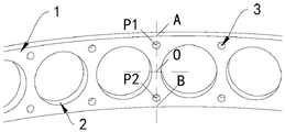
Referring to fig. 2, adjacent pockets 2 have a center line therebetween in a direction parallel to the axis of the ring body 1, and the process holes 3 are arranged along the center line. Therefore, the positions of the process holes 3 are regulated, and the process holes 3 can balance the overall structural strength of the annular main body 1.
Referring to fig. 2 and 3, the center line has an O point nearest to the centers of two adjacent pockets 2, the center line has an a point and a B point intersecting the edge of the ring body 1, the a point and the B point have the same first intensity, the O point has a second intensity, the first intensity is greater than the second intensity, the a point to the O point to the B point can form an intensity variation curve as shown in fig. 3, a half of the sum of the first intensity and the second intensity is set as a third intensity, in the intensity variation curve, the third intensity corresponds to a point P1 and a point P2, the point P1 is between the a point and the O point, the point P2 is between the B point and the O point, and the fabrication hole 3 is correspondingly set at the point P1 and/or the point P2.
Therefore, the strength (third strength) of the positions (point P1 and/or point P2) of the fabrication holes 3 is balanced with the strength of the parts of the annular main body 1 between the pockets 2, and further the strength distribution of each part of the bearing retainer with the pockets 2 can be uniformly balanced, thereby avoiding the above-mentioned bad phenomena and improving the working reliability of the bearing.
Referring to fig. 4, the pilot hole 3 is provided at one side of the pocket 2 in the axial direction of the ring body 1. From this, guaranteed the whole of annular main part 1 evenly balanced at axial direction intensity distribution, still made the bearing holder can be according to actual production and work needs, if for satisfying size or material requirement, select one side to set up wantonly. As can be appreciated by those skilled in the art to which the present application relates, the fabrication holes 3 may be discontinuously formed at one side of the pocket 2.
Referring to fig. 2, the process holes 3 are symmetrically disposed at both sides of the pocket 2 along the axial direction of the ring body 1. Therefore, the strength distribution of the whole annular main body 1 in all directions is ensured to be even and balanced. In addition, the arrangement also enables the bearing parts to be assembled without distinguishing the inner side direction and the outer side direction of the retainer, thereby being convenient for quick and convenient installation. As can be appreciated by those skilled in the art to which the present application relates, the fabrication holes 3 may be discontinuously spaced at both sides of the pocket 2.
Referring to fig. 5, the inner hole wall of the fabrication hole 3 is provided with an inward concave storage part 4. The storage part 4 is used for storing grease and foreign matters, can increase the flowing space of the grease in the rolling bearing, ensures that the grease flows smoothly, enhances the lubricating property, enhances the rolling property of the rolling body, reduces the friction of each part in the rolling bearing, and reduces the abrasion and the heating; the bearing retainer provides a gathering space for foreign matter particles entering the bearing from the outside or caused by wear and fracture of parts in the bearing, prevents the foreign matter from being clamped between the pocket 2 and the inner rolling body of the bearing or between the annular main body 1 and the inner ring and the outer ring of the bearing, prevents the rolling body from rolling, prevents the bearing retainer from running retardation and generating additional load, and avoids deterioration circulation.
When the rolling bearing rotates, under the action of centrifugal force and inertia force, the bearing retainer and the inner and outer rings of the bearing are extruded in different degrees, the grease has a movement trend towards the outer ring of the bearing, and can circularly flow between the bearing retainer and the inner and outer rings of the bearing due to extrusion, the flow space of the grease can be increased by the arrangement of the storage part 4, in addition, the grease can circularly flow with foreign matters, the foreign matters are prevented from being clamped between the pockets 2 and the inner rolling body of the bearing or between the annular main body 1 and the inner and outer rings of the bearing, structural abrasion is caused between the rolling body, the bearing retainer and the inner and outer rings of the bearing, more parts are damaged, and the phenomenon of vicious circle is formed.
Referring to fig. 5, the storage part 4 is an inner hole, and at least two inner holes are arranged at regular intervals along the inner hole wall of the fabrication hole 3. Thereby, not only the storage part 4 is provided, but also the whole structure balance of the bearing retainer is further ensured.
Referring to fig. 6, the storage portions 4 are formed as grooves, and at least two grooves are uniformly spaced along the circumferential direction of the inner hole wall of the fabrication hole 3. Therefore, the processing and the manufacturing are convenient, and the integral structural balance of the bearing retainer is further ensured.
Referring to fig. 7, the reservoir 4 is provided as an annular groove. Thereby, the processing and manufacturing are facilitated, and the space of the storage part 4 is increased.
As will be appreciated by those skilled in the art to which this application pertains, the reservoir 4 is a trench in a hole and may be formed by boring, typically on a boring machine, machining center, and combination machine using a single-blade boring tool.
Referring to fig. 8, the storage portion 4 is provided with a through-hole 5 provided along the radial direction of the ring-shaped body 1, and the through-hole 5 communicates the outside of the bearing holder with the inside of the storage portion 4. Therefore, the storage space of the grease is further increased, the fluidity of the grease is improved, the gathering, flowing and circulating of the grease are guided, and the lubricating effect is improved.
When the rolling bearing rotates, under the action of centrifugal force, inertia force and extrusion force of the bearing retainer and the inner ring and the outer ring of the bearing, the grease can drive foreign matters to circularly flow between the bearing retainer and the inner ring and the outer ring of the bearing, so that the through holes 5 further increase the flowing and storing space of the foreign matters, the foreign matters can enter the storing part 4 under the action of the centrifugal force and the inertia force to be clamped and stored or continuously flow under the drive of the grease, the foreign matters and impurities are effectively reduced or even avoided to exist between the pocket holes 2 and the inner rolling body of the bearing or between the annular main body 1 and the inner ring and the outer ring of the bearing, the working reliability of the bearing is improved, and even in heavy-load occasions, the retainer, the inner ring and the outer ring of the bearing and the rolling bodies can still be safe and careless.
Referring to fig. 9, the through-hole 5 is correspondingly provided in the side wall of the reservoir 4 near the bearing inner race. When the rolling bodies roll, under the action of centrifugal force, inertia force and extrusion force of the bearing retainer and the inner ring and the outer ring of the bearing, grease between the bearing retainer and the inner ring of the bearing can carry foreign matters to smoothly enter the storage part 4 through the through holes 5. This arrangement increases the grease reservoir space between the bearing holder and the bearing inner race, improves the fluidity of grease between the bearing holder and the bearing inner race, and guides grease and foreign matter between the bearing holder and the bearing inner race into the reservoir 4.
Referring to fig. 10, the through-hole 5 is provided in a side wall of the storage portion 4 away from the bearing inner race. When the rolling bodies roll, under the action of centrifugal force, inertia force and extrusion force of the bearing retainer and the inner and outer rings of the bearing, grease between the bearing retainer and the outer ring of the bearing can carry foreign matters to smoothly enter the storage part 4 through the through holes 5. Thereby, the grease storage space between the bearing holder and the bearing outer ring is increased, the fluidity of grease between the bearing holder and the bearing outer ring is improved, and grease and foreign matter between the bearing holder and the bearing outer ring are guided to enter the storage portion 4.
Referring to fig. 8, through-holes 5 are correspondingly formed in both side walls of the storage portion 4 facing the bearing inner ring and the bearing outer ring. When the rolling bodies roll, under the action of centrifugal force, inertia force and extrusion force of the bearing retainer and the inner and outer rings of the bearing, grease between the bearing retainer and the inner and outer rings of the bearing can carry foreign matters to smoothly enter the storage part 4 through the through holes 5. Thereby, the grease storage space between the bearing holder and the inner and outer races of the bearing is increased, the fluidity of grease between the bearing holder and the inner and outer races of the bearing is improved, and grease and foreign matter between the bearing holder and the inner and outer races of the bearing are guided to the reservoir 4.
In addition, as will be understood by those skilled in the art to which the present application relates, the through-hole 5 may be formed in various shapes such as a straight-through type or an arc type, for example, as shown in fig. 11, and grease and foreign materials may flow or be stored between the inner and outer rings of the bearing by being guided through the arc-shaped through-hole 5.
The embodiments in the present specification are described in a progressive manner, and the same and similar parts among the embodiments are referred to each other, and each embodiment focuses on the differences from the other embodiments. In particular, for the system embodiment, since it is substantially similar to the method embodiment, the description is simple, and for the relevant points, reference may be made to the partial description of the method embodiment.
The above are merely examples of the present invention, and are not intended to limit the present invention. Various modifications and alterations to this invention will become apparent to those skilled in the art. Any modification, equivalent replacement, improvement, etc. made within the spirit and principle of the present invention should be included in the scope of the claims of the present invention.
Claims (12)
1. A bearing retainer comprises an annular main body and pockets, and is characterized by further comprising process holes, wherein the process holes are arranged in the annular main body and are positioned in the parts between the adjacent pockets; a central line parallel to the axial direction of the annular main body is arranged between the adjacent pockets, and the fabrication holes are arranged along the central line; the central line is provided with an O point which is closest to the centers of two adjacent pockets, the central line is provided with an A point and a B point which are intersected with the edge of the annular main body, the A point and the B point have the same first strength, the O point has a second strength, the first strength is larger than the second strength, a strength change curve can be formed from the A point to the O point to the B point, a half of the sum of the first strength and the second strength is set as a third strength, in the strength change curve, the third strength corresponds to a P1 point and a P2 point, the P1 point is located between the A point and the O point, the P2 point is located between the B point and the O point, and the process holes are correspondingly arranged at the P1 point and/or the P2 point.
2. The bearing retainer of claim 1, wherein a plurality of said tooling holes are correspondingly formed in the same annular body, and are evenly spaced along a circumference of the annular body.
3. The bearing retainer of claim 1, wherein the tooling hole is disposed on a single side of the pocket in an axial direction of the annular body.
4. The bearing retainer of claim 1, wherein the tooling holes are symmetrically disposed on opposite sides of the pocket in an axial direction of the annular body.
5. The bearing retainer of claim 1, wherein the inner bore wall of the fabrication bore is provided with a recessed reservoir.
6. The bearing retainer of claim 5 wherein said reservoir is provided as an internal bore, said internal bore being provided in at least two spaced evenly spaced locations along an inner bore wall of said fabrication bore.
7. The bearing retainer of claim 5 wherein said reservoirs are provided as grooves, at least two of said grooves being evenly spaced circumferentially around the inner bore wall of said fabrication bore.
8. A bearing retainer according to claim 5 wherein said reservoir is provided as an annular groove.
9. A bearing retainer according to any one of claims 6 to 8, wherein the reservoir is provided with a through-hole arranged radially of the annular body, the through-hole communicating between the exterior of the bearing retainer and the interior of the reservoir.
10. The bearing retainer of claim 9, wherein the through-hole is correspondingly disposed adjacent to a sidewall of the reservoir of the bearing inner race.
11. The bearing retainer of claim 9, wherein the through-hole is correspondingly disposed in a sidewall of the reservoir portion remote from the bearing inner race.
12. The bearing retainer of claim 9, wherein the through-holes are formed in the two side walls of the storage portion facing the inner race and the outer race.
Priority Applications (1)
| Application Number | Priority Date | Filing Date | Title |
|---|---|---|---|
| CN202110355780.1A CN113090663B (en) | 2021-04-01 | 2021-04-01 | Bearing retainer |
Applications Claiming Priority (1)
| Application Number | Priority Date | Filing Date | Title |
|---|---|---|---|
| CN202110355780.1A CN113090663B (en) | 2021-04-01 | 2021-04-01 | Bearing retainer |
Publications (2)
| Publication Number | Publication Date |
|---|---|
| CN113090663A CN113090663A (en) | 2021-07-09 |
| CN113090663B true CN113090663B (en) | 2021-12-10 |
Family
ID=76672546
Family Applications (1)
| Application Number | Title | Priority Date | Filing Date |
|---|---|---|---|
| CN202110355780.1A Active CN113090663B (en) | 2021-04-01 | 2021-04-01 | Bearing retainer |
Country Status (1)
| Country | Link |
|---|---|
| CN (1) | CN113090663B (en) |
Citations (6)
| Publication number | Priority date | Publication date | Assignee | Title |
|---|---|---|---|---|
| CN102287448A (en) * | 2011-06-10 | 2011-12-21 | 洛阳美航汽车零部件有限公司 | Bearing cage |
| CN203308928U (en) * | 2013-05-06 | 2013-11-27 | 浙江五洲新春集团股份有限公司 | Cage for high-speed precision bearing |
| CN103727134A (en) * | 2013-12-11 | 2014-04-16 | 洛阳轴研科技股份有限公司 | Inner-guidance cylindrical roller bearing retainer and processing method thereof |
| JP2014234846A (en) * | 2013-05-31 | 2014-12-15 | Ntn株式会社 | Cage for rolling bearing, rolling bearing, and method of manufacturing cage for rolling bearing |
| CN204784203U (en) * | 2015-07-07 | 2015-11-18 | 杭州人本电机轴承有限公司 | Deep groove ball bearing ribbon cage monomer |
| CN108167337A (en) * | 2017-12-27 | 2018-06-15 | 中国航发哈尔滨轴承有限公司 | A kind of anti-light load slipping side's round hole cage |
-
2021
- 2021-04-01 CN CN202110355780.1A patent/CN113090663B/en active Active
Patent Citations (6)
| Publication number | Priority date | Publication date | Assignee | Title |
|---|---|---|---|---|
| CN102287448A (en) * | 2011-06-10 | 2011-12-21 | 洛阳美航汽车零部件有限公司 | Bearing cage |
| CN203308928U (en) * | 2013-05-06 | 2013-11-27 | 浙江五洲新春集团股份有限公司 | Cage for high-speed precision bearing |
| JP2014234846A (en) * | 2013-05-31 | 2014-12-15 | Ntn株式会社 | Cage for rolling bearing, rolling bearing, and method of manufacturing cage for rolling bearing |
| CN103727134A (en) * | 2013-12-11 | 2014-04-16 | 洛阳轴研科技股份有限公司 | Inner-guidance cylindrical roller bearing retainer and processing method thereof |
| CN204784203U (en) * | 2015-07-07 | 2015-11-18 | 杭州人本电机轴承有限公司 | Deep groove ball bearing ribbon cage monomer |
| CN108167337A (en) * | 2017-12-27 | 2018-06-15 | 中国航发哈尔滨轴承有限公司 | A kind of anti-light load slipping side's round hole cage |
Also Published As
| Publication number | Publication date |
|---|---|
| CN113090663A (en) | 2021-07-09 |
Similar Documents
| Publication | Publication Date | Title |
|---|---|---|
| WO2012023437A1 (en) | Rolling bearing and spindle device for machine tool | |
| US6315459B1 (en) | Synthetic resin cage for roller bearing | |
| JP2008240796A (en) | Angular contact ball bearing with seal, and spindle device | |
| CN109563879B (en) | Ball bearing, spindle device, and machine tool | |
| CN114810818A (en) | Rolling bearing with cage guide flange | |
| CN113090663B (en) | Bearing retainer | |
| CN201106625Y (en) | Locating bearing for high speed aluminium foil mill | |
| JP6556454B2 (en) | Ball bearing cage | |
| JP6493580B2 (en) | Angular contact ball bearings | |
| JP2014126195A (en) | Angular contact ball bearing | |
| CN215110094U (en) | Bearing retainer | |
| US2499640A (en) | Spindle bearing | |
| CN106050930B (en) | Rolling element bearing | |
| US20080075400A1 (en) | Rolling bearing apparatus | |
| JP5715001B2 (en) | Radial ball bearings | |
| WO2018034246A1 (en) | Ball bearing, and machine tool spindle device | |
| TWI708021B (en) | Cylindrical roller bearing | |
| KR20210138021A (en) | Angular ball bearings and retainers for angular ball bearings | |
| JP2002122149A (en) | Angular ball bearing, and machine tool using same | |
| CN113090664B (en) | Plastic-impregnated bearing retainer | |
| JP2008175329A (en) | Rolling bearing cage | |
| JP7186061B2 (en) | ball bearing | |
| JP4322641B2 (en) | Cylindrical roller bearing | |
| JP2006342820A (en) | Angular contact ball bearing | |
| JP2010002027A (en) | Cylindrical roller bearing and cylindrical roller bearing device |
Legal Events
| Date | Code | Title | Description |
|---|---|---|---|
| PB01 | Publication | ||
| PB01 | Publication | ||
| SE01 | Entry into force of request for substantive examination | ||
| SE01 | Entry into force of request for substantive examination | ||
| GR01 | Patent grant | ||
| GR01 | Patent grant |