CN113081596A - Medical electric suspension bridge equipment - Google Patents
Medical electric suspension bridge equipment Download PDFInfo
- Publication number
- CN113081596A CN113081596A CN202110331560.5A CN202110331560A CN113081596A CN 113081596 A CN113081596 A CN 113081596A CN 202110331560 A CN202110331560 A CN 202110331560A CN 113081596 A CN113081596 A CN 113081596A
- Authority
- CN
- China
- Prior art keywords
- fixedly connected
- suspension bridge
- convenient
- movable
- gear
- Prior art date
- Legal status (The legal status is an assumption and is not a legal conclusion. Google has not performed a legal analysis and makes no representation as to the accuracy of the status listed.)
- Pending
Links
Images


Classifications
-
- A—HUMAN NECESSITIES
- A61—MEDICAL OR VETERINARY SCIENCE; HYGIENE
- A61G—TRANSPORT, PERSONAL CONVEYANCES, OR ACCOMMODATION SPECIALLY ADAPTED FOR PATIENTS OR DISABLED PERSONS; OPERATING TABLES OR CHAIRS; CHAIRS FOR DENTISTRY; FUNERAL DEVICES
- A61G12/00—Accommodation for nursing, e.g. in hospitals, not covered by groups A61G1/00 - A61G11/00, e.g. trolleys for transport of medicaments or food; Prescription lists
- A61G12/002—Supply appliances, e.g. columns for gas, fluid, electricity supply
-
- A—HUMAN NECESSITIES
- A61—MEDICAL OR VETERINARY SCIENCE; HYGIENE
- A61B—DIAGNOSIS; SURGERY; IDENTIFICATION
- A61B50/00—Containers, covers, furniture or holders specially adapted for surgical or diagnostic appliances or instruments, e.g. sterile covers
- A61B50/20—Holders specially adapted for surgical or diagnostic appliances or instruments
-
- A—HUMAN NECESSITIES
- A61—MEDICAL OR VETERINARY SCIENCE; HYGIENE
- A61B—DIAGNOSIS; SURGERY; IDENTIFICATION
- A61B50/00—Containers, covers, furniture or holders specially adapted for surgical or diagnostic appliances or instruments, e.g. sterile covers
- A61B50/20—Holders specially adapted for surgical or diagnostic appliances or instruments
- A61B50/22—Racks
-
- A—HUMAN NECESSITIES
- A61—MEDICAL OR VETERINARY SCIENCE; HYGIENE
- A61B—DIAGNOSIS; SURGERY; IDENTIFICATION
- A61B50/00—Containers, covers, furniture or holders specially adapted for surgical or diagnostic appliances or instruments, e.g. sterile covers
- A61B50/20—Holders specially adapted for surgical or diagnostic appliances or instruments
- A61B50/24—Stands
-
- A—HUMAN NECESSITIES
- A61—MEDICAL OR VETERINARY SCIENCE; HYGIENE
- A61M—DEVICES FOR INTRODUCING MEDIA INTO, OR ONTO, THE BODY; DEVICES FOR TRANSDUCING BODY MEDIA OR FOR TAKING MEDIA FROM THE BODY; DEVICES FOR PRODUCING OR ENDING SLEEP OR STUPOR
- A61M5/00—Devices for bringing media into the body in a subcutaneous, intra-vascular or intramuscular way; Accessories therefor, e.g. filling or cleaning devices, arm-rests
- A61M5/14—Infusion devices, e.g. infusing by gravity; Blood infusion; Accessories therefor
- A61M5/1414—Hanging-up devices
- A61M5/1415—Stands, brackets or the like for supporting infusion accessories
-
- A—HUMAN NECESSITIES
- A61—MEDICAL OR VETERINARY SCIENCE; HYGIENE
- A61M—DEVICES FOR INTRODUCING MEDIA INTO, OR ONTO, THE BODY; DEVICES FOR TRANSDUCING BODY MEDIA OR FOR TAKING MEDIA FROM THE BODY; DEVICES FOR PRODUCING OR ENDING SLEEP OR STUPOR
- A61M5/00—Devices for bringing media into the body in a subcutaneous, intra-vascular or intramuscular way; Accessories therefor, e.g. filling or cleaning devices, arm-rests
- A61M5/14—Infusion devices, e.g. infusing by gravity; Blood infusion; Accessories therefor
- A61M5/1414—Hanging-up devices
- A61M5/1417—Holders or handles for hanging up infusion containers
-
- A—HUMAN NECESSITIES
- A61—MEDICAL OR VETERINARY SCIENCE; HYGIENE
- A61G—TRANSPORT, PERSONAL CONVEYANCES, OR ACCOMMODATION SPECIALLY ADAPTED FOR PATIENTS OR DISABLED PERSONS; OPERATING TABLES OR CHAIRS; CHAIRS FOR DENTISTRY; FUNERAL DEVICES
- A61G2203/00—General characteristics of devices
- A61G2203/70—General characteristics of devices with special adaptations, e.g. for safety or comfort
- A61G2203/72—General characteristics of devices with special adaptations, e.g. for safety or comfort for collision prevention
- A61G2203/723—Impact absorbing means, e.g. bumpers or airbags
Landscapes
- Health & Medical Sciences (AREA)
- Life Sciences & Earth Sciences (AREA)
- Surgery (AREA)
- Veterinary Medicine (AREA)
- Public Health (AREA)
- General Health & Medical Sciences (AREA)
- Animal Behavior & Ethology (AREA)
- Biomedical Technology (AREA)
- Heart & Thoracic Surgery (AREA)
- Engineering & Computer Science (AREA)
- Nuclear Medicine, Radiotherapy & Molecular Imaging (AREA)
- Medical Informatics (AREA)
- Molecular Biology (AREA)
- Hematology (AREA)
- Anesthesiology (AREA)
- Vascular Medicine (AREA)
- Nursing (AREA)
- Accommodation For Nursing Or Treatment Tables (AREA)
Abstract
The invention discloses medical electric suspension bridge equipment which comprises an installation mechanism, a suspension cross beam, a lifting mechanism, a limiting and damping mechanism and a movable plate. The invention has the beneficial effects that: installation mechanism is by the dead lever, fixed plate and fastening bolt constitute, be convenient for fix electronic suspension bridge equipment, it is more convenient that the dismouting gets up, elevating system is by motor drive, be convenient for adjust the height of device according to actual demand, use to make things convenient for medical personnel, spacing damper plays certain supporting role to the device, play certain cushioning effect simultaneously at the lift in-process, the surface of activity panel is provided with the spout, and the last surface slip of spout is provided with the movable table, be convenient for adjust the height of movable table as required, it is convenient to take, one side of carrier is connected with the pivot, the pivot is through the fixed infusion support that is provided with of fixed cover, and the lower extreme of infusion support is provided with the couple, be convenient for hang the infusion bottle, enrich the application scope of suspension bridge.
Description
Technical Field
The invention relates to suspension bridge equipment, in particular to medical electric suspension bridge equipment, and belongs to the technical field of medical instruments.
Background
Medical draw bridge is the medical equipment that is essential in the modern intensive care unit of hospital, and its mainly used places infusion support and various medical instrument, makes things convenient for medical personnel to the unified reasonable distribution cable of patient's diagnosis and treatment back to and be used for various medical gas piping's output terminal, the balanced type suspends the level that the instrument platform can be guaranteed to the crossbeam in midair, thereby guarantees medical instrument's safety, and convenient to use alright.
The medical suspension bridge of traditional form highly can't adjust when using, even if there is the regulation structure, also all adjusts through the people for, adjusts inefficiency, reduces doctor's work efficiency simultaneously, and current suspension bridge device structure is comparatively simple moreover, and the security performance is relatively poor.
Disclosure of Invention
The present invention has been made to solve the above problems, and an object of the present invention is to provide a medical electric suspension bridge apparatus.
The invention realizes the purpose through the following technical scheme: a medical electric suspension bridge device comprises an installation mechanism, a suspension cross beam, lifting mechanisms, limiting and damping mechanisms and movable plates, wherein an installation seat is fixedly installed on the upper side of the suspension cross beam, the lifting mechanisms are fixedly installed on two sides of the lower surface of the suspension cross beam, the limiting and damping mechanisms are fixedly arranged between the two lifting mechanisms, the upper end of each limiting and damping mechanism is fixedly connected with the lower surface of the suspension cross beam, the lifting mechanisms and the limiting and damping mechanisms are fixedly connected with the upper surface of the movable plates, two groups of rows of inserts are arranged on the surface of the movable plates, rotary seats are symmetrically installed on two sides of the lower surface of the movable plates, the lower side of each rotary seat is rotatably connected with a rotary shaft, a carrier is fixedly installed on the lower side of one rotary shaft, three carrier plates are fixedly arranged on the carrier, the carrier plates are fixed on the carrier through screws, and a, and a controller is fixedly installed between the two rotating seats and is fixedly connected with the lower surface of the movable plate.
As a still further scheme of the invention: the mounting mechanism is composed of a fixing rod, a fixing plate and a fastening bolt, one end of the fixing rod is fixedly connected with the upper surface of the suspension cross beam, the other end of the fixing rod is fixedly connected with the fixing plate, threaded holes are fixedly formed in the two sides of the fixing plate, and the fastening bolt is arranged in the threaded holes.
As a still further scheme of the invention: elevating system comprises motor, fixed frame, gear one, gear two, threaded rod, swivel nut, connecting rod, stopper one and spacing groove one, motor fixed mounting is in the outside of fixed frame, and the output of motor extends to the inside of fixed frame to with a gear rigid coupling, one side upper end gear engagement of gear one is connected with gear two, and gear two's lower extreme and threaded rod rigid coupling, the outside threaded connection of threaded rod has the swivel nut, the swivel nut is located the lower surface both sides rigid coupling of threaded rod has the connecting rod, two one side fixedly connected with stopper one of connecting rod, fixed being provided with on the inner wall of fixed frame with a stopper matched with spacing groove one.
As a still further scheme of the invention: spacing damper comprises spacing frame, spacing groove two, stopper two, movable block and spliced pole, the lower surface of spacing frame and the upper surface rigid coupling of fly leaf, the fixed spacing groove two that is provided with on the both sides inner wall of spacing frame, and slide in the spacing groove two in both sides and be provided with stopper two, two fixedly connected with movable block between the stopper two, the upper surface and the spliced pole rigid coupling of movable block, the upper end of spliced pole and the lower surface rigid coupling of hanging in midair the crossbeam.
As a still further scheme of the invention: the surface of the movable panel is provided with a sliding chute, and the upper surface of the sliding chute is provided with a movable table in a sliding manner.
As a still further scheme of the invention: one side of the carrier is connected with a rotating shaft, one end of the rotating shaft, which is far away from the carrier, is connected with a fixed sleeve, an infusion support is fixedly arranged inside the fixed sleeve, and a hook is arranged at the lower end of the infusion support.
The invention has the beneficial effects that: the medical electric suspension bridge equipment has reasonable design, the installation mechanism is composed of the fixed rod, the fixed plate and the fastening bolt, the electric suspension bridge equipment is convenient to fix and is convenient to disassemble and assemble, the lifting mechanism is driven by the motor, the height of the device is convenient to adjust according to actual requirements, so as to be convenient for medical staff to use, the limiting and damping mechanism plays a certain supporting role for the device, simultaneously plays a certain role in buffering in the lifting process, the surface of the movable panel is provided with a sliding chute, the upper surface of the sliding groove is provided with a movable table in a sliding way, the height of the movable table can be conveniently adjusted according to the requirement, the taking is convenient, one side of the object carrier is connected with a rotating shaft, one end of the rotating shaft, which is far away from the object carrier, is connected with a fixed sleeve, an infusion support is fixedly arranged inside the fixed sleeve, and the lower extreme of infusion support is provided with the couple, is convenient for hang the infusion bottle, enriches the application scope of draw bridge.
Drawings
FIG. 1 is a schematic view of the suspension bridge of the present invention;
FIG. 2 is a schematic view of the suspension bridge of the present invention;
FIG. 3 is an enlarged view of the structure at A in FIG. 2;
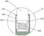
fig. 4 is an enlarged schematic view of B in fig. 2.
In the figure: 1. the device comprises a mounting mechanism, 2, a suspension beam, 3, a lifting mechanism, 4, a limiting and damping mechanism, 5, a movable plate, 6, a socket, 7, a rotating seat, 8, a rotating shaft, 9, a carrier, 10, a carrier plate, 11, an infusion support, 12, a fixed sleeve, 13, a rotating shaft, 14, a controller, 15, a movable panel, 101, a fixed rod, 102, a fixed plate, 103, a fastening bolt, 301, a motor, 302, a fixed frame, 303, a first gear, 304, a second gear, 305, a threaded rod, 306, a threaded sleeve, 307, a connecting rod, 308, a first limiting block, 309, a first limiting groove, 401, a limiting frame, 402, a second limiting groove, a second limiting block, 404, a movable block, 405 and a connecting column.
Detailed Description
The technical solutions in the embodiments of the present invention will be clearly and completely described below with reference to the drawings in the embodiments of the present invention, and it is obvious that the described embodiments are only a part of the embodiments of the present invention, and not all of the embodiments. All other embodiments, which can be derived by a person skilled in the art from the embodiments given herein without making any creative effort, shall fall within the protection scope of the present invention.
Example one
Referring to fig. 1-2, a medical electric suspension bridge device includes an installation mechanism 1, a suspension cross beam 2, lifting mechanisms 3, limiting and damping mechanisms 4 and a movable plate 5, wherein the installation base 1 is fixedly installed on the upper side of the suspension cross beam 2, the lifting mechanisms 3 are fixedly installed on two sides of the lower surface of the suspension cross beam 2, the limiting and damping mechanisms 4 are fixedly installed between the two lifting mechanisms 3, the upper ends of the limiting and damping mechanisms 4 are fixedly connected with the lower surface of the suspension cross beam 2, the lifting mechanisms 3 and the limiting and damping mechanisms 4 are fixedly connected with the upper surface of the movable plate 5, two sets of socket strips 6 are arranged on the surface of the movable plate 5, rotating bases 7 are symmetrically installed on two sides of the lower surface of the movable plate 5, a rotating shaft 8 is rotatably connected to the lower side of each rotating base 7, a carrier frame 9 is fixedly installed on the lower side of one rotating shaft 8, three carrier, the object carrying plate 10 is fixed on the object carrier 9 by screws, wherein a movable panel 15 is fixedly installed at the lower side of the other rotating shaft 8, a controller 14 is fixedly installed between the two rotating seats 7, and the controller 14 is fixedly connected with the lower surface of the movable plate 5.
In the embodiment of the invention, the surface of the movable panel 15 is provided with the sliding groove 16, and the upper surface of the sliding groove 16 is provided with the movable table 17 in a sliding manner, so that the height of the movable table 17 can be conveniently adjusted as required, and the movable table is convenient to take.
In the embodiment of the invention, one side of the carrier 9 is connected with a rotating shaft 13, one end of the rotating shaft 13, which is far away from the carrier 9, is connected with a fixed sleeve 12, an infusion support 11 is fixedly arranged inside the fixed sleeve 12, and the lower end of the infusion support 11 is provided with a hook, so that an infusion bottle can be conveniently hung, and the application range of the suspension bridge is widened.
Example two
Referring to fig. 1 to 3, a medical electric suspension bridge device includes an installation mechanism 1, a suspension cross beam 2, lifting mechanisms 3, a limiting and damping mechanism 4 and a movable plate 5, wherein the installation base 1 is fixedly installed on the upper side of the suspension cross beam 2, the lifting mechanisms 3 are fixedly installed on two sides of the lower surface of the suspension cross beam 2, and the limiting and damping mechanism 4 is fixedly installed between the two lifting mechanisms 3.
In the embodiment of the present invention, the mounting mechanism 1 is composed of a fixing rod 101, a fixing plate 102 and a fastening bolt 103, one end of the fixing rod 101 is fixedly connected to the upper surface of the suspension cross beam 2, the other end of the fixing rod 101 is fixedly connected to the fixing plate 102, threaded holes are fixedly arranged inside two sides of the fixing plate 102, and the fastening bolt 103 is arranged in the threaded holes, so that the electric suspension bridge equipment can be conveniently fixed, and the mounting and dismounting are convenient.
In the embodiment of the present invention, the lifting mechanism 3 is composed of a motor 301, a fixed frame 302, a first gear 303, a second gear 304, a threaded rod 305, a threaded sleeve 306, a connecting rod 307, a first limit block 308, and a first limit groove 309, the motor 301 is fixedly installed at the outer side of the fixed frame 302, the output end of the motor 301 extends to the inside of the fixed frame 302 and is fixedly connected with the first gear 303, the upper end of one side of the first gear 303 is connected with the second gear 304 in a gear meshing manner, the lower end of the second gear 304 is fixedly connected with the threaded rod 305, the outer side of the threaded rod 304 is connected with the threaded sleeve 306 in a threaded manner, the connecting rod 307 is fixedly connected to two sides of the lower surface of the threaded rod 304 of the threaded sleeve 306, the first limit block 308 is fixedly connected to one side of the two connecting rods 307, the first limit groove 309 matched with the first, so as to be convenient for medical staff to use.
EXAMPLE III
Referring to fig. 1 to 4, a medical electric suspension bridge device includes an installation mechanism 1, a suspension cross beam 2, lifting mechanisms 3, a limiting and damping mechanism 4 and a movable plate 5, wherein the installation base 1 is fixedly installed on the upper side of the suspension cross beam 2, the lifting mechanisms 3 are fixedly installed on two sides of the lower surface of the suspension cross beam 2, and the limiting and damping mechanism 4 is fixedly installed between the two lifting mechanisms 3.
In the embodiment of the invention, the limiting and shock-absorbing mechanism 4 is composed of a limiting frame 401, a limiting groove II 402, a limiting block II 403, a movable block 404 and a connecting column 405, the lower surface of the limiting frame 401 is fixedly connected with the upper surface of the movable plate 5, the limiting groove II 402 is fixedly arranged on the inner walls of two sides of the limiting frame 401, the limiting block II 403 is arranged in the limiting groove II 402 in a sliding mode, the movable block 404 is fixedly connected between the two limiting block II 403, the upper surface of the movable block 404 is fixedly connected with the connecting column 405, and the upper end of the connecting column 405 is fixedly connected with the lower surface of the suspension cross beam 2, so that a certain supporting effect on the device is achieved, and a certain buffering effect is achieved in the lifting.
The working principle is as follows: when the medical electric suspension bridge equipment is used, the suspension bridge equipment is fixedly installed through the matching action of the fixed rod 101, the fixed plate 102 and the fastening bolt 103 in the installation mechanism 1 and can be used, in the using process, the suspension bridge equipment can be subjected to height adjustment according to the most suitable operation height of a doctor, the threaded rod 305 is driven to rotate through the motor 301, and then the threaded sleeve 306 is driven to move up and down, so that the height adjustment of the movable plate 5 is realized, in the using process, required surgical instruments can be placed in the object carrying plate 10 arranged on the object carrying frame 9, the situation that the surgical instruments are placed in a mess and poor pollution is caused is avoided, the operation efficiency of the doctor is improved, when the patient needs to be transfused, the doctor adjusts the angle of the infusion support 11 through the rotating shaft 13, and then the infusion support can be suspended on the patient through the hook 11, the device can adjust the suspension bridge height through electronic mode, and it is efficient to adjust, and it is also relatively more stable to use.
It will be evident to those skilled in the art that the invention is not limited to the details of the foregoing illustrative embodiments, and that the present invention may be embodied in other specific forms without departing from the spirit or essential attributes thereof. The present embodiments are therefore to be considered in all respects as illustrative and not restrictive, the scope of the invention being indicated by the appended claims rather than by the foregoing description, and all changes which come within the meaning and range of equivalency of the claims are therefore intended to be embraced therein. Any reference sign in a claim should not be construed as limiting the claim concerned.
Furthermore, it should be understood that although the present description refers to embodiments, not every embodiment may contain only a single embodiment, and such description is for clarity only, and those skilled in the art should integrate the description, and the embodiments may be combined as appropriate to form other embodiments understood by those skilled in the art.
Claims (6)
1. The utility model provides a medical electronic draw bridge equipment which characterized in that: comprises an installation mechanism (1), a suspended cross beam (2), an elevating mechanism (3), a limiting damping mechanism (4) and a movable plate (5), wherein the installation mechanism (1) is fixedly installed at the upper side of the suspended cross beam (2), the elevating mechanism (3) is fixedly installed at two sides of the lower surface of the suspended cross beam (2), the limiting damping mechanism (4) is fixedly arranged between the elevating mechanism (3), the upper end of the limiting damping mechanism (4) is fixedly connected with the lower surface of the suspended cross beam (2), the elevating mechanism (3) and the limiting damping mechanism (4) are fixedly connected with the upper surface of the movable plate (5), two groups of insert rows (6) are arranged on the surface of the movable plate (5), rotary seats (7) are symmetrically installed at two sides of the lower surface of the movable plate (5), and the lower side of each rotary seat (7) is rotatably connected with a rotating shaft (, a carrier (9) is fixedly mounted on the lower side of one of the rotating shafts (8), three object carrying plates (10) are fixedly arranged on the carrier (9), the object carrying plates (10) are fixed on the carrier (9) through screws, a movable panel (15) is fixedly mounted on the lower side of the other rotating shaft (8), a controller (14) is fixedly mounted between the two rotating seats (7), and the controller (14) is fixedly connected with the lower surface of the movable plate (5).
2. The medical electric suspension bridge equipment according to claim 1, wherein: the mounting mechanism (1) is composed of a fixing rod (101), a fixing plate (102) and a fastening bolt (103), one end of the fixing rod (101) is fixedly connected with the upper surface of the suspension cross beam (2), the other end of the fixing rod (101) is fixedly connected with the fixing plate (102), threaded holes are fixedly formed in the inner portions of two sides of the fixing plate (102), and the fastening bolt (103) is arranged in the threaded holes.
3. The medical electric suspension bridge equipment according to claim 2, wherein: the lifting mechanism (3) comprises a motor (301), a fixed frame (302), a first gear (303), a second gear (304), a threaded rod (305), a threaded sleeve (306), a connecting rod (307), a first limit block (308) and a first limit groove (309), the motor (301) is fixedly installed on the outer side of the fixed frame (302), the output end of the motor (301) extends to the inside of the fixed frame (302) and is fixedly connected with the first gear (303), the upper end of one side of the first gear (303) is in gear engagement connection with the second gear (304), the lower end of the second gear (304) is fixedly connected with the threaded rod (305), the outer side of the threaded rod (304) is in threaded connection with the threaded sleeve (306), the lower surface of the threaded sleeve (306) located on the two sides of the threaded rod (304) is fixedly connected with the connecting rod (307), and the first limit block (308) is fixedly connected with one, and a first limiting groove (309) matched with the first limiting block (308) is fixedly arranged on the inner wall of the fixing frame (302).
4. The medical electric suspension bridge equipment according to claim 3, wherein: spacing damper (4) comprise spacing frame (401), spacing groove two (402), stopper two (403), movable block (404) and spliced pole (405), the lower surface of spacing frame (401) and the upper surface rigid coupling of fly leaf (5), the fixed spacing groove two (402) that is provided with on the both sides inner wall of spacing frame (401), and slide in spacing groove two (402) in both sides and be provided with stopper two (403), two fixedly connected with movable block (404) between stopper two (403), the upper surface and spliced pole (405) rigid coupling of movable block (404), the upper end of spliced pole (405) and the lower surface rigid coupling that suspends crossbeam (2) in midair.
5. The medical electric suspension bridge equipment according to claim 1, wherein: the surface of the movable panel (15) is provided with a sliding chute (16), and the upper surface of the sliding chute (16) is provided with a movable table (17) in a sliding manner.
6. The medical electric suspension bridge equipment according to claim 1, wherein: one side of the carrier (9) is connected with a rotating shaft (13), one end of the rotating shaft (13) far away from the carrier (9) is connected with a fixed sleeve (12), an infusion support (11) is fixedly arranged inside the fixed sleeve (12), and a hook is arranged at the lower end of the infusion support (11).
Priority Applications (1)
| Application Number | Priority Date | Filing Date | Title |
|---|---|---|---|
| CN202110331560.5A CN113081596A (en) | 2021-03-29 | 2021-03-29 | Medical electric suspension bridge equipment |
Applications Claiming Priority (1)
| Application Number | Priority Date | Filing Date | Title |
|---|---|---|---|
| CN202110331560.5A CN113081596A (en) | 2021-03-29 | 2021-03-29 | Medical electric suspension bridge equipment |
Publications (1)
| Publication Number | Publication Date |
|---|---|
| CN113081596A true CN113081596A (en) | 2021-07-09 |
Family
ID=76670697
Family Applications (1)
| Application Number | Title | Priority Date | Filing Date |
|---|---|---|---|
| CN202110331560.5A Pending CN113081596A (en) | 2021-03-29 | 2021-03-29 | Medical electric suspension bridge equipment |
Country Status (1)
| Country | Link |
|---|---|
| CN (1) | CN113081596A (en) |
Cited By (1)
| Publication number | Priority date | Publication date | Assignee | Title |
|---|---|---|---|---|
| CN116077280A (en) * | 2023-02-09 | 2023-05-09 | 李全祥 | Vehicle-mounted movable intelligent spiral CT medical emergency shelter |
Citations (7)
| Publication number | Priority date | Publication date | Assignee | Title |
|---|---|---|---|---|
| JP2013206471A (en) * | 2012-03-29 | 2013-10-07 | Codman Neuro Sciences Sarl | Reading device in wired communication with probe having embedded memory device |
| CN107582176A (en) * | 2017-08-29 | 2018-01-16 | 苏州科技城医院 | Operating room practicality single armed tower crane |
| CN208611215U (en) * | 2018-02-12 | 2019-03-19 | 江苏伟康洁婧医疗器械股份有限公司 | A kind of medical nursing suspension bridge |
| CN208989147U (en) * | 2018-06-26 | 2019-06-18 | 美东立(天津)医疗科技有限公司 | A kind of electronic Dual-arm crane tower of operating room gas supply |
| CN209595898U (en) * | 2018-06-26 | 2019-11-08 | 美东立(天津)医疗科技有限公司 | A kind of medical both arms tower crane carrying out multifunctional use |
| CN209966886U (en) * | 2019-01-21 | 2020-01-21 | 上海菲歌特医疗科技有限公司 | Medical suspension bridge device |
| CN212730269U (en) * | 2020-03-30 | 2021-03-19 | 南京迈瑞生物医疗电子有限公司 | Tower crane |
-
2021
- 2021-03-29 CN CN202110331560.5A patent/CN113081596A/en active Pending
Patent Citations (7)
| Publication number | Priority date | Publication date | Assignee | Title |
|---|---|---|---|---|
| JP2013206471A (en) * | 2012-03-29 | 2013-10-07 | Codman Neuro Sciences Sarl | Reading device in wired communication with probe having embedded memory device |
| CN107582176A (en) * | 2017-08-29 | 2018-01-16 | 苏州科技城医院 | Operating room practicality single armed tower crane |
| CN208611215U (en) * | 2018-02-12 | 2019-03-19 | 江苏伟康洁婧医疗器械股份有限公司 | A kind of medical nursing suspension bridge |
| CN208989147U (en) * | 2018-06-26 | 2019-06-18 | 美东立(天津)医疗科技有限公司 | A kind of electronic Dual-arm crane tower of operating room gas supply |
| CN209595898U (en) * | 2018-06-26 | 2019-11-08 | 美东立(天津)医疗科技有限公司 | A kind of medical both arms tower crane carrying out multifunctional use |
| CN209966886U (en) * | 2019-01-21 | 2020-01-21 | 上海菲歌特医疗科技有限公司 | Medical suspension bridge device |
| CN212730269U (en) * | 2020-03-30 | 2021-03-19 | 南京迈瑞生物医疗电子有限公司 | Tower crane |
Cited By (1)
| Publication number | Priority date | Publication date | Assignee | Title |
|---|---|---|---|---|
| CN116077280A (en) * | 2023-02-09 | 2023-05-09 | 李全祥 | Vehicle-mounted movable intelligent spiral CT medical emergency shelter |
Similar Documents
| Publication | Publication Date | Title |
|---|---|---|
| CN205031486U (en) | Medical nursing suspension bridge | |
| CN113081596A (en) | Medical electric suspension bridge equipment | |
| CN207990113U (en) | A kind of multi-angle suitable for the Web-based instruction is adjustable computer display frame | |
| CN213609581U (en) | Physical training device that sports teaching used | |
| CN214318459U (en) | Multifunctional breathing machine trolley | |
| CN112641579A (en) | Combined carbon fiber medical bed armrest | |
| CN210095923U (en) | Medical bridge type electric suspension bridge | |
| CN210873220U (en) | Drainage frame for large internal medicine department | |
| CN206120457U (en) | Medical suspension bridge | |
| CN208405128U (en) | wheelchair pedal lifting device and wheelchair | |
| CN219071059U (en) | ICU nursing unit combination crane tower | |
| CN220632479U (en) | Clinical operation mounted frame | |
| CN218899868U (en) | Suspension device | |
| CN214636597U (en) | Medical science inspection teaching intelligent operation platform | |
| CN218943338U (en) | Noninvasive dynamic respiration monitor mounting device | |
| CN212816640U (en) | Animal experiment operating table supporting synchronous display of multiple display screens | |
| CN221888509U (en) | Orthopedics joint gallows convenient to dismouting | |
| CN218720384U (en) | Television display support convenient to install | |
| CN213076908U (en) | Emergency department nurses with portable infusion support | |
| CN217697182U (en) | Medical electric suspension bridge | |
| CN221155121U (en) | Hanging physiotherapy equipment | |
| CN220193441U (en) | Suspension bridge | |
| CN211067703U (en) | Novel internal medicine nursing bracket | |
| CN212655442U (en) | Maintenance auxiliary device for electric power system | |
| CN215779393U (en) | Orthopedics wound postoperative gallows |
Legal Events
| Date | Code | Title | Description |
|---|---|---|---|
| PB01 | Publication | ||
| PB01 | Publication | ||
| SE01 | Entry into force of request for substantive examination | ||
| SE01 | Entry into force of request for substantive examination | ||
| RJ01 | Rejection of invention patent application after publication |
Application publication date: 20210709 |
|
| RJ01 | Rejection of invention patent application after publication |