CN113079552B - A kind of locomotive platform GSM-R network switching device and method - Google Patents

A kind of locomotive platform GSM-R network switching device and method Download PDF

Info

Publication number
CN113079552B
CN113079552B CN202110634082.5A CN202110634082A CN113079552B CN 113079552 B CN113079552 B CN 113079552B CN 202110634082 A CN202110634082 A CN 202110634082A CN 113079552 B CN113079552 B CN 113079552B
Authority
CN
China
Prior art keywords
gsm
switching
unit
voice
pin
Prior art date
Legal status (The legal status is an assumption and is not a legal conclusion. Google has not performed a legal analysis and makes no representation as to the accuracy of the status listed.)
Expired - Fee Related
Application number
CN202110634082.5A
Other languages
Chinese (zh)
Other versions
CN113079552A (en
Inventor
吕振文
黄志刚
郑彩顺
李世凯
刘征
殷保全
杨会心
赵堃
Current Assignee (The listed assignees may be inaccurate. Google has not performed a legal analysis and makes no representation or warranty as to the accuracy of the list.)
Tianjin 712 Mobile Communication Co Ltd
Original Assignee
Tianjin 712 Mobile Communication Co Ltd
Priority date (The priority date is an assumption and is not a legal conclusion. Google has not performed a legal analysis and makes no representation as to the accuracy of the date listed.)
Filing date
Publication date
Application filed by Tianjin 712 Mobile Communication Co Ltd filed Critical Tianjin 712 Mobile Communication Co Ltd
Priority to CN202110634082.5A priority Critical patent/CN113079552B/en
Publication of CN113079552A publication Critical patent/CN113079552A/en
Application granted granted Critical
Publication of CN113079552B publication Critical patent/CN113079552B/en
Expired - Fee Related legal-status Critical Current
Anticipated expiration legal-status Critical

Links

Images

Classifications

    • HELECTRICITY
    • H04ELECTRIC COMMUNICATION TECHNIQUE
    • H04WWIRELESS COMMUNICATION NETWORKS
    • H04W36/00Hand-off or reselection arrangements
    • H04W36/14Reselecting a network or an air interface
    • BPERFORMING OPERATIONS; TRANSPORTING
    • B61RAILWAYS
    • B61LGUIDING RAILWAY TRAFFIC; ENSURING THE SAFETY OF RAILWAY TRAFFIC
    • B61L15/00Indicators provided on the vehicle or train for signalling purposes
    • B61L15/0018Communication with or on the vehicle or train
    • B61L15/0027Radio-based, e.g. using GSM-R
    • HELECTRICITY
    • H04ELECTRIC COMMUNICATION TECHNIQUE
    • H04WWIRELESS COMMUNICATION NETWORKS
    • H04W4/00Services specially adapted for wireless communication networks; Facilities therefor
    • H04W4/30Services specially adapted for particular environments, situations or purposes
    • H04W4/40Services specially adapted for particular environments, situations or purposes for vehicles, e.g. vehicle-to-pedestrians [V2P]
    • H04W4/42Services specially adapted for particular environments, situations or purposes for vehicles, e.g. vehicle-to-pedestrians [V2P] for mass transport vehicles, e.g. buses, trains or aircraft
    • BPERFORMING OPERATIONS; TRANSPORTING
    • B61RAILWAYS
    • B61LGUIDING RAILWAY TRAFFIC; ENSURING THE SAFETY OF RAILWAY TRAFFIC
    • B61L2205/00Communication or navigation systems for railway traffic
    • B61L2205/02Global system for mobile communication - railways [GSM-R]

Landscapes

  • Engineering & Computer Science (AREA)
  • Computer Networks & Wireless Communication (AREA)
  • Signal Processing (AREA)
  • Aviation & Aerospace Engineering (AREA)
  • Mechanical Engineering (AREA)
  • Data Exchanges In Wide-Area Networks (AREA)

Abstract

本发明涉及一种机车台GSM‑R网络切换装置及方法,通过在标准型CIR的基础上,增加机车台装置单元,实现双G网接入的功能。机车台装置具备两组GSM‑R话音单元和GSM‑R数据单元,能够分别接入国内GSM‑R网络和国外GSM‑R网络,从而实现了一台机车台具备接入两个GSM‑R网络的能力。本发明在国内和国际上都是首次应用于跨境铁路机车上,为今后跨境铁路机车台的应用开发了一种新的模式,减少了机车安装空间的需求,并能够方便司机以及操作人员进行适应。既满足了用户的需求,也帮用户控制了设备的投入成本。

Figure 202110634082

The invention relates to a locomotive platform GSM-R network switching device and method, which realizes the function of double G network access by adding locomotive platform device units on the basis of standard CIR. The locomotive platform device has two sets of GSM‑R voice units and GSM‑R data units, which can be connected to the domestic GSM‑R network and the foreign GSM‑R network respectively, so that one locomotive platform can be connected to two GSM‑R networks. Ability. The invention is applied to cross-border railway locomotives for the first time both domestically and internationally, and develops a new mode for the application of cross-border railway locomotives in the future, which reduces the demand for installation space of the locomotive, and can facilitate drivers and operators. Adapt. It not only meets the needs of users, but also helps users control the investment cost of equipment.

Figure 202110634082

Description

Locomotive platform GSM-R network switching device and method
Technical Field
The invention relates to a railway communication locomotive platform device, in particular to a locomotive platform GSM-R network switching device and method used for a cross-border train.
Background
The traditional locomotive integrated radio communication equipment CIR (China railway general company enterprise standard: Q/CR 651.1-2018 locomotive integrated radio communication equipment part 1: technical conditions) is shown in figure 11, a main machine comprises an A sub-frame and a B sub-frame, the A sub-frame comprises a GSM-R voice unit and a GSM-R data unit, and the main machine only has the function of accessing a group of GSM-R networks.
(patent number of invention: CN 106059875) (CIR for short in the following), the host only has one group of GSM-R network communication modules, which are GSM-R voice unit and GSM-R data unit, respectively, and also only has the function of accessing one group of GSM-R network.
According to the operation requirements of the existing cross-border railway high-speed motor train unit train and freight train, the motor train unit needs to be directly operated from China to abroad, but the foreign GSM-R network and the domestic GSM-R network cannot be interconnected, and no more space is provided between the locomotive equipment for installing two sets of locomotive platforms, one is used for domestic use, and the other is used for foreign use.
In this case, the existing CIR cannot meet the operation requirement of the cross-border railway train.
Disclosure of Invention
In order to solve the problem of cross-border railway train communication urgently and meet cross-border requirements of motor train units, freight trains and the like, and to solve the problems that the cross-border railway train needs to be accessed into a domestic GSM-R network during domestic operation and needs to be accessed into a foreign GSM-R network during foreign operation, and a locomotive does not have redundant space to install two sets of locomotive platforms, a locomotive platform G network switching device is additionally arranged on the basis of an existing CIR, the access of the two GSM-R networks can be conveniently realized, the railway transportation requirements are met, and therefore the dual-G network function is achieved, and the operation requirements of cross-border railways can be met.
The technical scheme adopted by the invention is as follows: a locomotive platform GSM-R network switching device comprises a power supply switching circuit I, a power supply switching circuit II, a power supply switching circuit III, a switching control unit, a GSM-R voice switching unit, a GSM-R data switching unit, a domestic GSM-R voice unit, a domestic GSM-R data unit, a foreign GSM-R voice unit and a foreign GSM-R data unit;
the power supply input from the power supply input socket P2 is used for providing power supply for the switching control unit, the GSM-R voice switching unit, the GSM-R data switching unit, the domestic GSM-R voice unit, the domestic GSM-R data unit, the foreign GSM-R voice unit and the foreign GSM-R data unit through the power supply switching circuit I, the power supply switching circuit II and the power supply switching circuit III;
the switching control unit is respectively connected with the GSM-R voice switching unit and the GSM-R data switching unit,
the GSM-R voice switching unit is respectively connected with the domestic GSM-R voice unit and the foreign GSM-R voice unit,
the GSM-R data switching unit is respectively connected with a domestic GSM-R data unit and a foreign GSM-R data unit;
the power input socket P2, the communication interface D3 of the switching control unit, the voice transfer socket D4 of the GSM-R voice switching unit, the data transfer socket D5 of the GSM-R data switching unit, the antenna interface T1 of the domestic GSM-R voice unit, the antenna interface T2 of the domestic GSM-R data unit, the antenna interface T3 of the foreign GSM-R voice unit and the antenna interface T4 of the foreign GSM-R data unit are respectively arranged on the panel of the chassis of the locomotive platform device.
A method for switching a device of a GSM-R network of a locomotive platform comprises the following steps:
the a1 socket of the B sub-rack of the CIR equipment is connected to the MMI,
the power input socket P2 of the locomotive G network switching device is connected with the power output socket P1 of the CIR equipment A sub-frame,
the communication interface D3 of the switching control unit of the locomotive G network switching device is connected with the port B2 of the B sub-frame of the CIR equipment,
the transfer socket D4 of the GSM-R voice switching unit of the switching device of the locomotive G network is connected with the transfer socket D1 of the GSM-R voice unit of the CIR equipment A sub-frame,
the transfer socket D5 of the GSM-R data switching unit of the locomotive G network switching device is connected with the GSM-R data unit transfer socket D2 of the CIR equipment A sub-frame,
respectively connecting an antenna interface T1 of a domestic GSM-R voice unit, an antenna interface T2 of a domestic GSM-R data unit, an antenna interface T3 of a foreign GSM-R voice unit and an antenna interface T4 of a foreign GSM-R data unit with an antenna;
1) starting up the self-detection process:
after the power is turned on, the main control unit of the A sub-rack inquires the state of the last power-off, and whether the GSM-R network is at home or abroad:
if the last GSM-R network state after inquiry is domestic, the switching operation steps are as follows:
the main control unit of the A sub-frame informs a switching control unit of a G network switching device of a locomotive platform to control 16 switching doors in a GSM-R voice switching unit and a GSM-R data switching unit, the path is switched to the domestic, and after the switching is finished, domestic network registration, locomotive function number registration and train number function number registration are finished;
if the last GSM-R network state after inquiry is foreign, the switching operation steps are as follows:
the main control unit of the A sub-frame informs a switching control unit of a G network switching device of a locomotive platform to control 16-way switching doors in a GSM-R voice switching unit and a GSM-R data switching unit, the access is switched to abroad, and after the switching is finished, foreign network registration, locomotive function number registration and train number function number registration are finished;
2) and (3) manual switching flow:
A. switching to a foreign GSM-R network:
when the used network is a domestic GSM-R network and needs to be switched to a foreign GSM-R network, the operation flow steps are as follows:
operating on MMI of CIR equipment by an operator, pressing a 'CN/LA' key, selecting 'switching to foreign GSM-R network' on an interface, and pressing a 'confirm' key;
after the operation is finished, the MMI is sent to the main control unit of the A subframe of the CIR through a message, and after the CIR main control unit receives the message, the CIR main control unit performs domestic function number logout and network logout work;
after the logout is finished, the A sub-frame main control unit of the CIR informs a switching control unit of the locomotive platform device to control 16 paths of switching doors in the GSM-R voice switching unit and the GSM-R data switching unit and switch the path to the foreign country;
after the switching is completed, the GSM-R voice unit of the CIR equipment A sub-frame connected with the voice transfer socket D4 is connected to the foreign GSM-R voice unit through a line, and the GSM-R data unit of the CIR equipment A sub-frame connected with the data transfer socket D5 is connected to the foreign GSM-R data unit through a line;
after the switching is completed, the main control unit of CIR equipment makes foreign GSM-R network registration and function number registration,
after the registration is finished, the whole switching operation is finished;
B. switching to a domestic GSM-R network:
when the used network is a foreign GSM-R network and needs to be switched to a domestic GSM-R network, the operation flow is as follows:
operating on MMI of CIR equipment by an operator, pressing a 'CN/LA' key, selecting 'switching to a domestic GSM-R network' on an interface, and pressing a 'confirm' key;
after the operation is finished, the MMI is sent to a main control unit of the A subframe of the CIR through a message, and after the CIR main control unit receives the message, the CIR main control unit performs foreign function number logout and network logout work;
after the logout is finished, the A subframe main control unit of the CIR informs the switching control unit to control 16 paths of switching doors in the voice switching unit and the GSM-R data switching unit and switch the paths to the 'domestic';
after the switching is completed, the GSM-R voice unit of the CIR equipment connected with the voice transfer socket D4 is connected to the domestic GSM-R voice unit through a line, and the GSM-R data unit of the CIR equipment A sub-frame connected with the data transfer socket D5 is connected to the domestic GSM-R data unit through a line;
after the switching is completed, the CIR equipment main control unit performs domestic GSM-R network registration and function number registration, and after the registration is completed, the whole switching operation is completed.
The invention has the following beneficial effects:
1. the problem that two CIRs cannot be installed due to limited space of the locomotive is solved, the GSM-R network access device has access to a domestic or foreign GSM-R network, and switching can be performed by operating an MMI.
2. The method solves the urgent need for an implementation mode in a short period and meets the problem of locomotive communication after the cross-border railway is opened.
3. The investment cost is reduced, the requirement of two GSM-R network accesses is realized by only increasing the locomotive platform device on the basis of the existing CIR, and the investment is low.
4. The function is realized fast, and partial software is modified in a controllable range by increasing the locomotive platform device, so that the function can be realized, and the reliability of the equipment is improved.
5. The demonstration effect is that the requirement of cross-border railway transportation is met through an additional mode, and a new mode is developed for multi-mode development and application of equipment under the conditions that China railways are out of China and network systems, modes, working modes and the like are inconsistent.
In a word, the locomotive platform device comprises two groups of G network units, namely a domestic GSM-R voice unit and a GSM-R data unit, and a foreign GSM-R voice unit and a GSM-R data unit; the locomotive platform device comprises two groups of switching units which are respectively used for switching the GSM-R voice communication interface and the GSM-R data communication interface.
Can be respectively accessed to the domestic GSM-R network and the foreign GSM-R network, thereby realizing that one locomotive platform has the capability of being accessed to the two GSM-R networks.
The invention is applied to the cross-border railway locomotive for the first time domestically and internationally, develops a new mode for the application of the cross-border railway locomotive platform in the future, reduces the requirement of the locomotive installation space, can facilitate the adaptation of drivers and operators, not only meets the requirement of users, but also helps the users to control the input cost of equipment.
The locomotive platform device comprises two groups of G network units, can meet requirements in a short time, and has the characteristics of small investment, quick application and high reliability.
Drawings
FIG. 1 is a schematic block diagram of a locomotive G-network switching device of the present invention;
FIG. 2 is a schematic connection diagram of the G-net switching device, the A sub-frame, the B sub-frame and the MMI of the locomotive platform of the invention;
FIG. 3 is a block diagram of the circuit for switching to the domestic GSM-R network according to the present invention;
FIG. 4 is a block diagram of the circuit for switching to a foreign GSM-R network according to the present invention;
FIG. 5 is a circuit diagram of the power conversion of-5V of the present invention
FIG. 6 is a circuit diagram of the GSM-R voice unit power supply in the country of the present invention;
FIG. 7 is a circuit diagram of the foreign GSM-R voice unit power supply of the present invention;
FIG. 8 is a circuit diagram of a switching control unit according to the present invention;
FIG. 9 is a GSM-R voice switching unit of the present invention;
FIG. 10 is a GSM-R data switch unit according to the present invention;
fig. 11 is a schematic diagram of the CIR of the prior art.
Detailed Description
The device connection and operation flow are further described in the following with reference to the drawings and the embodiments.
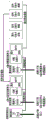
As shown in fig. 1 to 4, a locomotive platform GSM-R network switching device comprises a network switching device arranged on a rack, wherein a power conversion circuit i, a power conversion circuit ii, a power conversion circuit iii, a switching control unit, a GSM-R voice switching unit, a GSM-R data switching unit, a domestic GSM-R voice unit, a domestic GSM-R data unit, a foreign GSM-R voice unit and a foreign GSM-R data unit are arranged in the network switching device.
The power supply input from the power supply input socket D provides power supply for the switching control unit, the GSM-R voice switching unit, the GSM-R data switching unit, the domestic GSM-R voice unit, the domestic GSM-R data unit, the foreign GSM-R voice unit and the foreign GSM-R data unit through the power supply switching circuit I, the power supply switching circuit II and the power supply switching circuit III respectively;
the switching control unit is respectively connected with the GSM-R voice switching unit and the GSM-R data switching unit,
the GSM-R voice switching unit is respectively connected with the domestic GSM-R voice unit and the foreign GSM-R voice unit, and the GSM-R data switching unit is respectively connected with the domestic GSM-R data unit and the foreign GSM-R data unit;
the power input socket P2, the communication interface D3 of the switching control unit, the voice transfer socket D4 of the GSM-R voice switching unit, the data transfer socket D5 of the GSM-R data switching unit, the antenna interface T1 of the domestic GSM-R voice unit, the antenna interface T2 of the domestic GSM-R data unit, the antenna interface T3 of the foreign GSM-R voice unit and the antenna interface T4 of the foreign GSM-R data unit are respectively arranged on the panel of the chassis of the locomotive platform device.
A method for switching a device of a GSM-R network of a locomotive platform comprises the following steps:
the a1 socket of the B sub-rack of the CIR equipment is connected to the MMI,
the power input socket P2 of the locomotive G network switching device is connected with the power output socket P1 of the CIR equipment A sub-frame,
the communication interface D3 of the switching control unit of the locomotive G network switching device is connected with the port B2 of the B sub-frame of the CIR equipment,
the voice transfer socket D4 of the GSM-R voice switching unit of the switching device of the locomotive G network is connected with the GSM-R voice unit transfer socket D1 of the CIR equipment A sub-frame,
the data adapter socket D5 of the GSM-R data switching unit of the locomotive G network switching device is connected with the GSM-R data unit adapter socket D2 of the CIR equipment A sub-frame,
respectively connecting an antenna interface T1 of a domestic GSM-R voice unit, an antenna interface T2 of a domestic GSM-R data unit, an antenna interface T3 of a foreign GSM-R voice unit and an antenna interface T4 of a foreign GSM-R data unit with an antenna;
1) starting up the self-detection process;
after the power-on and power-on of the mobile terminal, the switching control unit inquires the state of the last power-off, whether the GSM-R network is at home or abroad, and if the state of the last GSM-R network after inquiry is at home, the switching operation steps are as follows:
the switching control unit controls 11 pin K1 of the processor N8B to be low level, after 29 pin K1 of 16-channel switching gate circuit chip N12 in the GSM-R voice switching unit receives the low level, the channel is switched to the country, after the switching is finished, the GSM-R voice unit switching socket D1 of CIR equipment A sub-frame is connected to the switching socket D4 of the voice switching unit, thus being connected to the domestic GSM-R voice unit;
the switching control unit controls a pin 11K 1 of the processor N8B to be at a low level, a pin 29K 1 of a 16-way switching gate circuit chip N17 in the GSM-R data switching unit switches the access to the country after receiving the low level, and after the switching is finished, a GSM-R data unit switching socket D2 of a sub-frame of the CIR equipment A is connected to a switching socket D5 of the data switching unit so as to be connected to the domestic GSM-R data unit;
if the last GSM-R network state after inquiry is foreign, the switching operation steps are as follows:
the switching control unit controls 11 pin K1 of the processor N8B to be high level, after 29 pin K1 of 16-channel switching gate circuit chip N12 in the GSM-R voice switching unit receives the high level, the channel is switched to abroad, after the switching is finished, the GSM-R voice unit switching socket D1 of the CIR equipment A sub-frame is connected to the switching socket D4 of the voice switching unit, thereby being connected to the foreign GSM-R voice unit;
the switching control unit controls a pin K1 of a processor N8B to be in a high level, a pin K1 of a pin 29K 17 of a 16-way switching gate circuit chip N17 in the GSM-R data switching unit receives the high level and switches a channel to abroad, and after the switching is finished, a GSM-R data unit switching socket D2 of a sub-frame of the CIR equipment A is connected to a switching socket D5 of the data switching unit so as to be connected to the foreign GSM-R data unit;
2) and (3) manual switching flow:
A. switching to a foreign GSM-R network:
when the used network is a domestic GSM-R network and needs to be switched to a foreign GSM-R network, the operation flow steps are as follows:
operating on MMI of CIR equipment by an operator, pressing a 'CN/LA' key, selecting 'switching to foreign GSM-R network' on an interface, and pressing a 'confirm' key;
after the operation is finished, the MMI (operation display terminal) is sent to a main control unit of the CIR equipment through a message, and after the CIR main control unit receives the message, the CIR main control unit performs domestic function number logout and network logout work; after the log-off is completed, the CIR main control unit forwards a switching command to a switching control unit of the locomotive platform G network switching device through a port B2 and a communication interface D3 in sequence, and the switching process is as follows:
the switching control unit controls 11 pin K1 of the processor N8B to be high level, after 29 pin K1 of 16-channel switching gate circuit chip N12 in the GSM-R voice switching unit receives the high level, the channel is switched to abroad, after the switching is finished, the GSM-R voice unit switching socket D1 of the CIR equipment A sub-frame is connected to the switching socket D4 of the voice switching unit, thereby being connected to the foreign GSM-R voice unit;
the switching control unit controls a pin K1 of a processor N8B to be in a high level, a pin K1 of a pin 29K 17 of a 16-way switching gate circuit chip N17 in the GSM-R data switching unit receives the high level and switches a channel to abroad, and after the switching is finished, a GSM-R data unit switching socket D2 of a sub-frame of the CIR equipment A is connected to a switching socket D5 of the data switching unit so as to be connected to the foreign GSM-R data unit;
after the switching is completed, the main control unit of CIR equipment makes foreign GSM-R network registration and function number registration,
after the registration is finished, the whole switching operation is finished;
B. switching to a domestic GSM-R network:
when the used network is a foreign GSM-R network and needs to be switched to a domestic GSM-R network, the operation flow is as follows:
operating on MMI of CIR equipment by an operator, pressing a 'CN/LA' key, selecting 'switching to a domestic GSM-R network' on an interface, and pressing a 'confirm' key;
after the operation is finished, the MMI is sent to the CIR main control unit through a message, and after the CIR main control unit receives the message, the CIR main control unit performs foreign function number logout and network logout work;
after the log-off is completed, the CIR main control unit forwards a switching command to a switching control unit of the locomotive platform G network switching device through a port B2 and a communication interface D3 in sequence, and the switching process is as follows:
the switching control unit controls 11 pin K1 of the processor N8B to be low level, after 29 pin K1 of 16-channel switching gate circuit chip N12 in the GSM-R voice switching unit receives the low level, the channel is switched to the country, after the switching is finished, the GSM-R voice unit switching socket D1 of CIR equipment A sub-frame is connected to the switching socket D4 of the voice switching unit, thus being connected to the domestic GSM-R voice unit;
the switching control unit controls a pin 11K 1 of the processor N8B to be at a low level, a pin 29K 1 of a 16-way switching gate circuit chip N17 in the GSM-R data switching unit switches the access to the country after receiving the low level, and after the switching is finished, a GSM-R data unit switching socket D2 of a sub-frame of the CIR equipment A is connected to a switching socket D5 of the data switching unit so as to be connected to the domestic GSM-R data unit;
after the switching is completed, the CIR equipment main control unit performs domestic GSM-R network registration and function number registration, and after the registration is completed, the whole switching operation is completed.
1. A power supply path switching circuit of the locomotive platform device;
as shown in fig. 5, the power conversion circuit i converts 13.8V power input from the power input socket P2 into 6V voltage through the power chip N2, and then converts 6V into 5V voltage through the power chip N3, and respectively transmits the voltage to the switching control unit, the GSM-R voice switching unit, the GSM-R data switching unit, the domestic GSM-R voice unit, the domestic GSM-R data unit, the foreign GSM-R voice unit, and the foreign GSM-R data unit, and the circuit reliability is increased through two-stage voltage conversion; the model of the power supply chip N2 is LM2596, and the model of the power supply chip N3 is MIC 29301-5.0.
As shown in fig. 6, the power conversion circuit ii inputs 13.8V power from the power input socket P2, and converts the voltage of 13.8V into 12V through the power chip N1, so as to provide power for the GSM-R voice units abroad;
as shown in fig. 7, the power conversion circuit iii inputs 13.8V power to the power input socket P2, and converts the voltage of 13.8V to 12V through the power chip N4 to supply power to the domestic GSM-R voice unit;
the domestic GSM-R voice unit and the foreign GSM-R voice unit are respectively and independently powered, so that the stability of the power supply of each voice unit is ensured;
the models of the power supply chip N1 and the power supply chip N4 are MIC29301-ADJ, respectively.
2. Switching the internal circuit of the control unit;
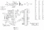
as shown in fig. 8, the communication chip N7 of the switching control unit circuit is used for TTL and 422 data conversion, wherein pins 5, 6, 7 and 8 are used for connecting the communication interface D3 of the switching control unit, and pins 2 and 3 are used for connecting pins 75 and 81 of the processor N8B for communication;
the processor N8 is a controller of the switching control unit, and is configured to process a communication packet of an existing CIR device, and control a switching operation of the switching unit, where pins 75 and 81 are used for communicating with the communication chip N7, and pins 3, 7, 8, 9, 10, and 11 are control pins for controlling the switching unit, and the switching unit is controlled by controlling the pins to be at a low level and a high level;
the voltage stabilizer chip N6 is used for converting 5V voltage into 3.3V voltage and supplying power to the CPU;
the USB interface chip N10 is connected with the processor through pins 1, 2 and 3, and completes a hardware path of data transmission through the interface chip;
the switching control unit controls the switching unit to perform switching operation through the high and low levels of the 11 pin K1 of the processor N8B;
the model of the communication chip N7 is MAX490, the model of the processor N8 is LPC4337JBD144, the model of the voltage stabilizer chip N6 is SPX1117-3.3, and the model of the USB interface chip N10 is PRTR5V0U 4D.
3. Internal circuits of the GSM-R voice switching unit and the GSM-R data switching unit;
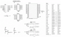
as shown in fig. 9, the GSM-R voice switching unit, gate chip N12 is a 16-way switching gate for switching the communication interface of the GSM-R voice unit;
the relays N15 and N16 are double-pole double-throw relays and are used for switching MIC voice and SP voice of the GSM-R voice unit;
drivers N13 and N14 are chips for enhancing pin driving capability;
a pin K1 of the switching unit socket XS1, for controlling the switching circuit;
the model of the gate circuit chip N12 is 74CBT16233DGGRE4, the models of the relays N15 and N16 are G6K-2F, and the models of the drivers N13 and N14 are SN74HCT245 DBR.
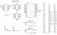
As shown in fig. 10, the GSM-R data switching unit, gate chip N17 is a 16-way switching gate for switching the communication interface of the GSM-R voice unit;
the relays N20 and N21 are double-pole double-throw relays and are used for switching MIC voice and SP voice of the GSM-R voice unit;
drivers N18 and N19 are chips for enhancing pin driving capability;
a pin K1 of the switching unit socket XS2, for controlling the switching circuit;
the model of the gate circuit chip N17 is 74CBT16233DGGRE4, the models of the relays N20 and N21 are G6K-2F, and the models of the drivers N18 and N19 are SN74HCT245 DBR.
4. The principle of switching control flows;
1) switching to the domestic GSM-R network:
in the switching process of the GSM-R voice unit, when a pin K1 of a socket XS1 is at a low level, a pin K1 of a pin 29 of a gate chip N12 is also at a low level, a pin A1-A12 of a socket D4 is converted into a pin 1A-12A after passing through enhanced pin driving capability of drivers N13 and N14, then the pin 1A-12A is connected to a corresponding pin of a 16-way switching gate, and at the moment, because the pin K1 of the gate chip N12 is at a low level, the pin 1A-12A is correspondingly connected with the corresponding pin 1B1-12B 1; when the pin K1 of the socket XS1 is low, the 13A-16A of the socket D4 is connected to the 13B1-16B1 through the relays N15 and N16 controlled by the K1, and then the GSM-R voice channel is switched to the home.
In the switching process of the GSM-R data unit, when a pin K1 of a socket XS2 is at a low level, a pin K1 of a pin 29 of a gate chip N17 is also at a low level, a pin A1-A12 of a socket D5 is converted into a pin 1A-12A after passing through enhanced pin driving capability of drivers N13 and N14, then the pin 1A-12A is connected to a corresponding pin of a 16-way switching gate, and at the moment, because the pin K1 of the gate chip N17 is at a low level, the pin 1A-12A is correspondingly connected with the corresponding pin 1B1-12B 1; when the pin K1 of the socket XS2 is low, the 13A-16A of the socket D5 is connected to the 13B1-16B1 through the relays N20 and N21 controlled by the K1, and the GSM-R data path is switched to the home.
2) Switching to foreign GSM-R network:
in the switching process of the GSM-R voice unit, when a pin K1 of a socket XS1 is at a high level, a pin K1 of a pin 29 of a gate chip N12 is also at a high level, a pin A1-A12 of a socket D4 is converted into a pin 1A-12A after passing through enhanced pin driving capability of drivers N13 and N14, then the pin 1A-12A is connected to a corresponding pin of a 16-way switching gate, and at the moment, because the pin K1 of the gate chip N12 is at a high level, the pin 1A-12A is correspondingly connected with the corresponding pin 1B2-12B 2; when the pin K1 of the socket XS1 is high, the 13A-16A of the socket D4 is connected to the 13B2-16B2 through the relays N15 and N16 controlled by the K1, and the GSM-R voice channel is switched to abroad.
In the switching process of the GSM-R data unit, when a pin K1 of a socket XS2 is at a high level, a pin K1 of a pin 29 of a gate chip N17 is also at a high level, a pin A1-A12 of a socket D5 is converted into a pin 1A-12A after passing through enhanced pin driving capability of drivers N13 and N14, then the pin 1A-12A is connected to a corresponding pin of a 16-way switching gate, and at the moment, because the pin K1 of the gate chip N17 is at a high level, the pin 1A-12A is correspondingly connected with the corresponding pin 1B2-12B 2; when the pin K1 of the socket XS2 is high, the 13A-16A of the socket D5 is connected to the 13B2-16B2 through the relays N20 and N21 controlled by the K1, and the GSM-R data path is switched to abroad.

Claims (8)

1.一种机车台GSM-R网络切换装置,其特征在于:包括电源转换电路Ⅰ、电源转换电路Ⅱ、电源转换电路Ⅲ、切换控制单元、GSM-R话音切换单元、GSM-R数据切换单元、国内GSM-R话音单元、国内GSM-R数据单元、国外GSM-R话音单元和国外GSM-R数据单元;1. A GSM-R network switching device for locomotive platform is characterized in that: comprising power conversion circuit I, power conversion circuit II, power conversion circuit III, switching control unit, GSM-R voice switching unit, GSM-R data switching unit , domestic GSM-R voice unit, domestic GSM-R data unit, foreign GSM-R voice unit and foreign GSM-R data unit; 从电源输入插座P2输入的电源,分别通过电源转换电路Ⅰ、电源转换电路Ⅱ、电源转换电路Ⅲ为切换控制单元、GSM-R话音切换单元、GSM-R数据切换单元、国内GSM-R话音单元、国内GSM-R数据单元、国外GSM-R话音单元和国外GSM-R数据单元提供电源;The power input from the power input socket P2 passes through the power conversion circuit I, power conversion circuit II, and power conversion circuit III respectively as the switching control unit, the GSM-R voice switching unit, the GSM-R data switching unit, and the domestic GSM-R voice unit. , Provide power for domestic GSM-R data unit, foreign GSM-R voice unit and foreign GSM-R data unit; 所述切换控制单元分别与GSM-R话音切换单元和GSM-R数据切换单元连接,The switching control unit is respectively connected with the GSM-R voice switching unit and the GSM-R data switching unit, GSM-R话音切换单元分别与国内GSM-R话音单元和国外GSM-R话音单元连接,The GSM-R voice switching unit is respectively connected with the domestic GSM-R voice unit and the foreign GSM-R voice unit, 所述GSM-R数据切换单元分别与国内GSM-R数据单元和国外GSM-R数据单元连接;The GSM-R data switching unit is respectively connected with the domestic GSM-R data unit and the foreign GSM-R data unit; 电源输入插座P2、切换控制单元的通信接口D3、GSM-R话音切换单元的话音转接插座D4、GSM-R数据切换单元的数据转接插座D5、国内GSM-R话音单元的天线接口T1、国内GSM-R数据单元的天线接口T2、国外GSM-R话音单元的天线接口T3和国外GSM-R数据单元的天线接口T4分别设置在机车台装置机箱面板上。Power input socket P2, communication interface D3 of switching control unit, voice switching socket D4 of GSM-R voice switching unit, data switching socket D5 of GSM-R data switching unit, antenna interface T1 of domestic GSM-R voice unit, The antenna interface T2 of the domestic GSM-R data unit, the antenna interface T3 of the foreign GSM-R voice unit and the antenna interface T4 of the foreign GSM-R data unit are respectively arranged on the chassis panel of the locomotive platform device. 2.根据权利要求1所述的一种机车台GSM-R网络切换装置,其特征在于:2. a kind of locomotive platform GSM-R network switching device according to claim 1, is characterized in that: 所述电源转换电路Ⅰ将电源输入插座P2输入的13.8V电源,经过电源芯片N2将13.8V转换为6V电压,然后经过电源芯片N3将6V转换为5V电压,分别输送到切换控制单元、GSM-R话音切换单元、GSM-R数据切换单元、国内GSM-R话音单元、国内GSM-R数据单元、国外GSM-R话音单元和国外GSM-R数据单元,通过两级电压转换,增加了电路可靠性;电源芯片N2 的型号为LM2596,电源芯片N3的型号为MIC29301-5.0。The power conversion circuit I converts the 13.8V power input from the power input socket P2 into a 6V voltage through the power chip N2, and then converts the 6V into a 5V voltage through the power chip N3, and sends them to the switching control unit, GSM- R voice switching unit, GSM-R data switching unit, domestic GSM-R voice unit, domestic GSM-R data unit, foreign GSM-R voice unit and foreign GSM-R data unit, through two-stage voltage conversion, increase the reliability of the circuit The model of power chip N2 is LM2596, and the model of power chip N3 is MIC29301-5.0. 3.根据权利要求1所述的一种机车台GSM-R网络切换装置,其特征在于:所述电源转换电路Ⅱ将电源输入插座P2输入13.8V电源,经过电源芯片N1将13.8V电压转换为12V,为国外GSM-R话音单元提供电源;3. A locomotive platform GSM-R network switching device according to claim 1, wherein the power conversion circuit II inputs a 13.8V power supply through the power input socket P2, and converts the 13.8V voltage into a 13.8V power supply through the power supply chip N1. 12V, providing power for foreign GSM-R voice units; 所述电源转换电路Ⅲ将电源输入插座P2输入13.8V电源,经过电源芯片N4将13.8V电压转换为12V,为国内GSM-R话音单元提供电源;The power conversion circuit III inputs a 13.8V power supply into the power input socket P2, and converts the 13.8V voltage to 12V through the power supply chip N4 to provide power for the domestic GSM-R voice unit; 国内GSM-R话音单元和国外GSM-R话音单元分别单独供电,保证了每个话音单元的电源稳定;The domestic GSM-R voice unit and the foreign GSM-R voice unit are separately powered to ensure the power supply of each voice unit is stable; 电源芯片N1和电源芯片N4的型号分别为MIC29301-ADJ。The models of the power chip N1 and the power chip N4 are MIC29301-ADJ respectively. 4.根据权利要求1所述的一种机车台GSM-R网络切换装置,其特征在于:4. a kind of locomotive platform GSM-R network switching device according to claim 1, is characterized in that: 所述切换控制单元电路的通信芯片N7用于进行TTL和422数据转换,其中5、6、7、8引脚用于连接切换控制单元的通信接口D3,2、3脚用于连接处理器N8B的75脚和81脚进行通信;The communication chip N7 of the switching control unit circuit is used for TTL and 422 data conversion, wherein pins 5, 6, 7, and 8 are used to connect to the communication interface D3 of the switching control unit, and pins 2 and 3 are used to connect to the processor N8B 75 feet and 81 feet to communicate; 处理器N8为切换控制单元的控制器,用于处理既有CIR设备的通信报文,控制切换单元的切换操作,其中75、81脚用于和通信芯片N7进行通信,3、7、8、9、10、11脚为控制切换单元的控制引脚,通过控制此引脚为低电平和高电平来控制切换单元;The processor N8 is the controller of the switching control unit, which is used to process the communication messages of the existing CIR equipment and control the switching operation of the switching unit. Among them, pins 75 and 81 are used to communicate with the communication chip N7. Pins 9, 10, and 11 are the control pins for controlling the switching unit, and the switching unit is controlled by controlling this pin to be low level and high level; 稳压器芯片N6用于将5V电压转换为3.3V电压,为CPU供电;The voltage regulator chip N6 is used to convert the 5V voltage to 3.3V voltage to supply power to the CPU; USB接口芯片N10通过1、2、3引脚与处理器相连接,通过接口芯片,完成USB数据传输的硬件通路;The USB interface chip N10 is connected to the processor through pins 1, 2 and 3, and completes the hardware path of USB data transmission through the interface chip; 切换控制单元通过处理器N8B的11脚K1的高、低电平控制切换单元进行切换操作;The switching control unit controls the switching unit to perform switching operations through the high and low levels of the 11-pin K1 of the processor N8B; 稳压器芯片N6的型号为 SPX1117-3.3,通信芯片N7的型号为MAX490,处理器N8的型号为LPC4337JBD144 ,USB接口芯片N10型号为PRTR5V0U4D。The model of the voltage regulator chip N6 is SPX1117-3.3, the model of the communication chip N7 is MAX490, the model of the processor N8 is LPC4337JBD144, and the model of the USB interface chip N10 is PRTR5V0U4D. 5.根据权利要求1所述的一种机车台GSM-R网络切换装置,其特征在于:5. a kind of locomotive platform GSM-R network switching device according to claim 1, is characterized in that: 所述GSM-R话音切换单元,门电路芯片N12为16路切换门,用于切换GSM-R话音单元的通信接口;In the GSM-R voice switching unit, the gate circuit chip N12 is a 16-way switching gate, which is used for switching the communication interface of the GSM-R voice unit; 继电器N15、N16为双刀双掷,用于切换GSM-R话音单元的MIC话音和SP话音;Relays N15 and N16 are double-pole double-throw, used to switch the MIC voice and SP voice of the GSM-R voice unit; 驱动器N13、N14为增强管脚驱动能力芯片;Drivers N13 and N14 are chips for enhancing pin driving capability; 切换单元插座XS1的K1脚,用于控制切换电路;The K1 pin of the switching unit socket XS1 is used to control the switching circuit; 门电路芯片N12的型号为74CBT16233DGGRE4,继电器N15、N16型号为G6K-2F,驱动器N13、N14的型号为SN74HCT245DBR。The model of gate circuit chip N12 is 74CBT16233DGGRE4, the model of relay N15 and N16 is G6K-2F, and the model of driver N13 and N14 is SN74HCT245DBR. 6.根据权利要求1所述的一种机车台GSM-R网络切换装置,其特征在于:6. A kind of locomotive platform GSM-R network switching device according to claim 1, is characterized in that: 所述GSM-R数据切换单元,门电路芯片N17为16路切换门,用于切换GSM-R话音单元的通信接口;In the GSM-R data switching unit, the gate circuit chip N17 is a 16-way switching gate, which is used for switching the communication interface of the GSM-R voice unit; 继电器N20、N21为双刀双掷,用于切换GSM-R话音单元的MIC话音和SP话音;Relays N20 and N21 are double-pole double-throw, used to switch the MIC voice and SP voice of the GSM-R voice unit; 驱动器N18、N19为增强管脚驱动能力芯片;Drivers N18 and N19 are chips for enhancing pin driving capability; 切换单元插座XS2的K1脚,用于控制切换电路;The K1 pin of the switching unit socket XS2 is used to control the switching circuit; 门电路芯片N17的型号为74CBT16233DGGRE4,继电器N20、N21型号为G6K-2F,驱动器N18、N19的型号为SN74HCT245DBR。The model of gate circuit chip N17 is 74CBT16233DGGRE4, the model of relay N20 and N21 is G6K-2F, and the model of driver N18 and N19 is SN74HCT245DBR. 7.一种采用权利要求1所述的机车台GSM-R网络切换装置的方法,其特征在于,步骤如下:7. A method for adopting the locomotive platform GSM-R network switching device according to claim 1, wherein the steps are as follows: CIR设备B子架的A1插座与MMI连接,The A1 socket of the B subrack of the CIR device is connected to the MMI, 将机车台G网切换装置的电源输入座P2与CIR设备A子架的电源输出插座P1连接,Connect the power input socket P2 of the locomotive platform G network switching device to the power output socket P1 of the CIR equipment A subframe, 将机车台G网切换装置切换控制单元的通信接口D3与CIR设备B子架的B2口连接,Connect the communication interface D3 of the switching control unit of the locomotive platform G network switching device to the B2 port of the CIR equipment B sub-frame, 将机车台G网切换装置GSM-R话音切换单元的转接插座D4与CIR设备A子架的GSM-R话音单元转接插座D1连接,Connect the adapter socket D4 of the GSM-R voice switching unit of the locomotive platform G network switching device to the GSM-R voice unit adapter socket D1 of the CIR equipment A subrack, 将机车台G网切换装置GSM-R数据切换单元的转接插座D5与CIR设备A子架的GSM-R数据单元转接插座D2连接,Connect the adapter socket D5 of the GSM-R data switching unit of the locomotive platform G network switching device to the GSM-R data unit adapter socket D2 of the CIR equipment A sub-rack, 将国内GSM-R话音单元的天线接口T1、国内GSM-R数据单元的天线接口T2、国外GSM-R话音单元的天线接口T3和国外GSM-R数据单元的天线接口T4分别连接一个天线;Connect the antenna interface T1 of the domestic GSM-R voice unit, the antenna interface T2 of the domestic GSM-R data unit, the antenna interface T3 of the foreign GSM-R voice unit and the antenna interface T4 of the foreign GSM-R data unit to an antenna respectively; 1)开机自检测过程:1) Power-on self-test process: 开机上电后,A子架的主控单元查询上次关机时的状态,GSM-R网络是处于国内还是国外:After the power is turned on, the main control unit of subrack A inquires about the status of the last shutdown, whether the GSM-R network is in China or abroad: 如查询后上次的GSM-R网络状态为国内时,进行切换操作步骤如下:If the last GSM-R network status after the query is domestic, the switching operation steps are as follows: A子架的主控单元通知机车台G网切换装置的切换控制单元,控制GSM-R话音切换单元和GSM-R数据切换单元中的16路切换门,将通路切换到国内,切换完成后,完成国内网络注册、机车功能号和车次功能号注册;The main control unit of subframe A notifies the switching control unit of the locomotive platform G network switching device to control the 16-way switching gates in the GSM-R voice switching unit and the GSM-R data switching unit, and switch the channel to the domestic. After the switching is completed, Complete domestic network registration, locomotive function number and train function number registration; 如查询后上次的GSM-R网络状态为国外时,进行切换操作步骤如下:If the last GSM-R network status after the query is foreign, the switching operation steps are as follows: A子架的主控单元通知机车台G网切换装置的切换控制单元,控制GSM-R话音切换单元和GSM-R数据切换单元中的16路切换门,将通路切换到国外,切换完成后,完成国外网络注册、机车功能号和车次功能号注册;The main control unit of sub-frame A notifies the switching control unit of the G network switching device of the locomotive platform to control the 16-channel switching gates in the GSM-R voice switching unit and the GSM-R data switching unit, and switch the channel to foreign countries. Complete foreign network registration, locomotive function number and train function number registration; 2)手动切换流程:2) Manual switching process: A、切换为国外GSM-R网络:A. Switch to foreign GSM-R network: 当使用网络为国内GSM-R网络,需要切换到国外GSM-R网络,操作流程步骤如下:When the network used is a domestic GSM-R network, it is necessary to switch to a foreign GSM-R network. The operation process steps are as follows: 由操作人员在CIR设备的MMI上进行操作,按“CN/LA”按键,在界面选择“切换到国外GSM-R网络”,并按“确认”键;The operator shall operate on the MMI of the CIR device, press the "CN/LA" button, select "Switch to foreign GSM-R network" on the interface, and press the "Confirm" button; 操作完成后,MMI通过报文发送给CIR的A子架的主控单元,CIR主控单元收到后,CIR主控单元进行国内功能号注销、网络注销工作;After the operation is completed, the MMI sends the message to the main control unit of subrack A of the CIR. After the CIR main control unit receives it, the CIR main control unit performs domestic function number cancellation and network cancellation; 注销完成后,CIR的A子架主控单元通知机车台装置的切换控制单元,控制GSM-R话音切换单元和GSM-R数据切换单元中的16路切换门,将通路切换到“国外”;After the cancellation is completed, the main control unit of the sub-frame A of the CIR informs the switching control unit of the locomotive platform device, controls the 16-way switching doors in the GSM-R voice switching unit and the GSM-R data switching unit, and switches the channel to "overseas"; 切换完成后,与话音转接插座D4连接的CIR设备A子架的GSM-R话音单元通过线路连接到国外GSM-R话音单元,与数据转接插座D5连接的CIR设备A子架的GSM-R数据单元通过线路连接到国外GSM-R数据单元;After the switching is completed, the GSM-R voice unit of the CIR equipment A subrack connected to the voice switching socket D4 is connected to the foreign GSM-R voice unit through the line, and the GSM-R voice unit of the CIR equipment A subrack connected to the data switching socket D5. The R data unit is connected to the foreign GSM-R data unit through the line; 切换完成后,CIR设备的主控单元进行国外GSM-R网络注册、功能号注册,After the handover is completed, the main control unit of the CIR device performs foreign GSM-R network registration and function number registration. 注册完成后,整个切换操作完成;After the registration is completed, the entire switching operation is completed; B、切换为国内GSM-R网络:B. Switch to domestic GSM-R network: 当使用网络为国外GSM-R网络,需要切换到国内GSM-R网络,操作流程如下:When using a foreign GSM-R network, you need to switch to a domestic GSM-R network. The operation process is as follows: 由操作人员在CIR设备的MMI上进行操作,按“CN/LA”按键,在界面选择“切换到国内GSM-R网络”,并按“确认”键;The operator operates on the MMI of the CIR device, presses the "CN/LA" button, selects "Switch to domestic GSM-R network" on the interface, and presses the "OK" button; 操作完成后,MMI通过报文发送给CIR的A子架的主控单元,CIR主控单元收到后,CIR主控单元进行国外功能号注销、网络注销工作;After the operation is completed, the MMI sends a message to the main control unit of the subrack A of the CIR. After the CIR main control unit receives it, the CIR main control unit performs foreign function number cancellation and network cancellation; 注销完成后,CIR的A子架主控单元通知切换控制单元,控制话音切换单元和GSM-R数据切换单元中的16路切换门,将通路切换到“国内”;After the cancellation is completed, the main control unit of the CIR subrack A notifies the switching control unit to control the 16-way switching gates in the voice switching unit and the GSM-R data switching unit, and switch the channel to "domestic"; 切换完成后,与话音转接插座D4连接的CIR设备的GSM-R话音单元通过线路连接到国内GSM-R话音单元,与数据转接插座D5连接的CIR设备A子架的GSM-R数据单元通过线路连接到国内GSM-R数据单元;After the switching is completed, the GSM-R voice unit of the CIR equipment connected to the voice switching socket D4 is connected to the domestic GSM-R voice unit through the line, and the GSM-R data unit of the CIR equipment A subrack connected to the data switching socket D5 Connect to the domestic GSM-R data unit through the line; 切换完成后,CIR设备主控单元进行国内GSM-R网络注册、功能号注册,注册完成后,整个切换操作完成。After the handover is completed, the main control unit of the CIR equipment performs domestic GSM-R network registration and function number registration. After the registration is completed, the entire handover operation is completed. 8.根据权利要求7所述的一种机车台GSM-R网络切换装置的方法,其特征在于:8. the method for a kind of locomotive platform GSM-R network switching device according to claim 7, is characterized in that: 所述切换到国内GSM-R网络的具体过程为:The specific process of switching to the domestic GSM-R network is as follows: GSM-R话音单元的切换过程,当插座XS1的K1脚为低电平时,门电路芯片N12的29脚K1脚也为低电平,插座D4的A1-A12经过驱动器N13、N14的增强管脚驱动能力后,转换为1A-12A,然后1A-12A引脚连接到16路切换门的对应引脚处,此时因为门电路芯片N12的29脚K1为低电平,所以引脚1A-12A与对应引脚1B1-12B1对应连接; 当插座XS1的K1脚为低电平时,插座D4的13A-16A,通过K1控制的继电器N15、N16,连接到13B1-16B1,此时GSM-R话音通路切换到国内;During the switching process of the GSM-R voice unit, when the K1 pin of the socket XS1 is at a low level, the 29-pin K1 pin of the gate circuit chip N12 is also a low level, and the A1-A12 of the socket D4 pass through the enhanced pins of the drivers N13 and N14. After the driving ability, it is converted to 1A-12A, and then the 1A-12A pin is connected to the corresponding pin of the 16-way switching gate. At this time, because the 29-pin K1 of the gate circuit chip N12 is low, so the pin 1A-12A Correspondingly connected with the corresponding pins 1B1-12B1; when the K1 pin of the socket XS1 is at a low level, the 13A-16A of the socket D4 are connected to 13B1-16B1 through the relays N15 and N16 controlled by K1, and the GSM-R voice channel is at this time. switch to domestic; GSM-R数据单元的切换过程,当插座XS2的K1脚为低电平时,门电路芯片N17的29脚K1脚也为低电平,插座D5的A1-A12经过驱动器N13、N14的增强管脚驱动能力后,转换为1A-12A,然后1A-12A引脚连接到16路切换门的对应引脚处,此时因为门电路芯片N17的29脚K1为低电平,所以引脚1A-12A与对应引脚1B1-12B1对应连接; 当插座XS2的K1脚为低电平时,插座D5的13A-16A,通过K1控制的继电器N20、N21,连接到13B1-16B1,此时GSM-R数据通路切换到国内;During the switching process of the GSM-R data unit, when the K1 pin of the socket XS2 is at a low level, the 29-pin K1 pin of the gate circuit chip N17 is also a low level, and the A1-A12 of the socket D5 pass through the enhanced pins of the drivers N13 and N14. After the driving ability, it is converted to 1A-12A, and then the 1A-12A pin is connected to the corresponding pin of the 16-way switching gate. At this time, because the 29-pin K1 of the gate circuit chip N17 is low, so the pin 1A-12A Correspondingly connected with the corresponding pins 1B1-12B1; when the K1 pin of the socket XS2 is at a low level, the 13A-16A of the socket D5 are connected to 13B1-16B1 through the relays N20 and N21 controlled by K1, at this time the GSM-R data path switch to domestic; 所述切换到国外GSM-R网络的具体过程为:The specific process of switching to a foreign GSM-R network is as follows: GSM-R话音单元的切换过程,当插座XS1的K1脚为高电平时,门电路芯片N12的29脚K1脚也为高电平,插座D4的A1-A12经过驱动器N13、N14的增强管脚驱动能力后,转换为1A-12A,然后1A-12A引脚连接到16路切换门的对应引脚处,此时因为门电路芯片N12的29脚K1为高电平,所以引脚1A-12A与对应引脚1B2-12B2对应连接; 当插座XS1的K1脚为高电平时,插座D4的13A-16A,通过K1控制的继电器N15、N16,连接到13B2-16B2,此时GSM-R话音通路切换到国外;During the switching process of the GSM-R voice unit, when the K1 pin of the socket XS1 is at a high level, the 29-pin K1 pin of the gate circuit chip N12 is also a high level, and the A1-A12 of the socket D4 pass through the enhanced pins of the drivers N13 and N14. After the driving ability, it is converted to 1A-12A, and then the 1A-12A pin is connected to the corresponding pin of the 16-way switching gate. At this time, because the 29-pin K1 of the gate circuit chip N12 is high, so the pin 1A-12A Correspondingly connected with the corresponding pins 1B2-12B2; When the K1 pin of the socket XS1 is at a high level, the 13A-16A of the socket D4 are connected to 13B2-16B2 through the relays N15 and N16 controlled by K1, and the GSM-R voice channel is at this time. switch to a foreign country; GSM-R数据单元的切换过程,当插座XS2的K1脚为高电平时,门电路芯片N17的29脚K1脚也为高电平,插座D5的A1-A12经过驱动器N13、N14的增强管脚驱动能力后,转换为1A-12A,然后1A-12A引脚连接到16路切换门的对应引脚处,此时因为门电路芯片N17的29脚K1为高电平,所以引脚1A-12A与对应引脚1B2-12B2对应连接; 当插座XS2的K1脚为高电平时,插座D5的13A-16A,通过K1控制的继电器N20、N21,连接到13B2-16B2,此时GSM-R数据通路切换到国外。During the switching process of the GSM-R data unit, when the K1 pin of the socket XS2 is at a high level, the 29-pin K1 pin of the gate circuit chip N17 is also a high level, and the A1-A12 of the socket D5 pass through the enhanced pins of the drivers N13 and N14. After the driving ability, it is converted to 1A-12A, and then the 1A-12A pin is connected to the corresponding pin of the 16-way switching gate. At this time, because the 29-pin K1 of the gate circuit chip N17 is high, so the pin 1A-12A Correspondingly connected with the corresponding pins 1B2-12B2; when the K1 pin of the socket XS2 is at a high level, the 13A-16A of the socket D5, through the relays N20 and N21 controlled by K1, are connected to 13B2-16B2, at this time the GSM-R data path Switch to abroad.
CN202110634082.5A 2021-06-08 2021-06-08 A kind of locomotive platform GSM-R network switching device and method Expired - Fee Related CN113079552B (en)

Priority Applications (1)

Application Number Priority Date Filing Date Title
CN202110634082.5A CN113079552B (en) 2021-06-08 2021-06-08 A kind of locomotive platform GSM-R network switching device and method

Applications Claiming Priority (1)

Application Number Priority Date Filing Date Title
CN202110634082.5A CN113079552B (en) 2021-06-08 2021-06-08 A kind of locomotive platform GSM-R network switching device and method

Publications (2)

Publication Number Publication Date
CN113079552A CN113079552A (en) 2021-07-06
CN113079552B true CN113079552B (en) 2021-08-17

Family

ID=76617090

Family Applications (1)

Application Number Title Priority Date Filing Date
CN202110634082.5A Expired - Fee Related CN113079552B (en) 2021-06-08 2021-06-08 A kind of locomotive platform GSM-R network switching device and method

Country Status (1)

Country Link
CN (1) CN113079552B (en)

Families Citing this family (1)

* Cited by examiner, † Cited by third party
Publication number Priority date Publication date Assignee Title
CN114124271A (en) * 2021-11-24 2022-03-01 中车大连机车车辆有限公司 Radio station automatic switching method of power-concentrated motor train unit running across countries

Citations (6)

* Cited by examiner, † Cited by third party
Publication number Priority date Publication date Assignee Title
CN205249193U (en) * 2015-10-14 2016-05-18 飞天联合(北京)系统技术有限公司 On -vehicle server of multichannel
CN106788833A (en) * 2016-12-12 2017-05-31 天津七二通信广播股份有限公司 A kind of bimodulus row tail locomotive station
CN206993109U (en) * 2017-05-19 2018-02-09 深圳市思科泰技术股份有限公司 A kind of railroad train small comprehensive Wireless Telecom Equipment
CN207766270U (en) * 2017-12-20 2018-08-24 天津七一二通信广播股份有限公司 A kind of GSM-R row tail locomotive station monitor station
CN110712667A (en) * 2018-07-12 2020-01-21 北京全路通信信号研究设计院集团有限公司 Comprehensive train control system capable of adapting to foreign requirements
CN111163441A (en) * 2020-04-03 2020-05-15 北京全路通信信号研究设计院集团有限公司 Dual-mode vehicle-mounted radio station system

Family Cites Families (1)

* Cited by examiner, † Cited by third party
Publication number Priority date Publication date Assignee Title
US7471655B2 (en) * 2003-10-17 2008-12-30 Kineto Wireless, Inc. Channel activation messaging in an unlicensed mobile access telecommunications system

Patent Citations (6)

* Cited by examiner, † Cited by third party
Publication number Priority date Publication date Assignee Title
CN205249193U (en) * 2015-10-14 2016-05-18 飞天联合(北京)系统技术有限公司 On -vehicle server of multichannel
CN106788833A (en) * 2016-12-12 2017-05-31 天津七二通信广播股份有限公司 A kind of bimodulus row tail locomotive station
CN206993109U (en) * 2017-05-19 2018-02-09 深圳市思科泰技术股份有限公司 A kind of railroad train small comprehensive Wireless Telecom Equipment
CN207766270U (en) * 2017-12-20 2018-08-24 天津七一二通信广播股份有限公司 A kind of GSM-R row tail locomotive station monitor station
CN110712667A (en) * 2018-07-12 2020-01-21 北京全路通信信号研究设计院集团有限公司 Comprehensive train control system capable of adapting to foreign requirements
CN111163441A (en) * 2020-04-03 2020-05-15 北京全路通信信号研究设计院集团有限公司 Dual-mode vehicle-mounted radio station system

Non-Patent Citations (1)

* Cited by examiner, † Cited by third party
Title
《城市轨道交通信号系统兼容推广可行性分析》;吴矿宁等;《信息记录材料》;20180731;全文 *

Also Published As

Publication number Publication date
CN113079552A (en) 2021-07-06

Similar Documents

Publication Publication Date Title
CN112689264B (en) A locomotive wireless synchronous control communication platform and method
CN113079552B (en) A kind of locomotive platform GSM-R network switching device and method
KR102233152B1 (en) OCPP protocol electric vehicle charging system
CN106603668A (en) Elevator internet-of-things intelligent box and system
CN112202571A (en) A POE power transmission device, POE switch and POE system
CN102938659A (en) NFC (Near Field Communication) external member and realization method thereof
JP3179398B2 (en) Simple mobile phone base station equipment
CN216310554U (en) Signal conversion circuit for platform door control signals
CN104917511B (en) A kind of interface circuit of the RF power amplification mould group of the compatible MIPI and GPIO control of energy
WO2010148826A1 (en) Method and device for reducing power consumption of dual-mode single-standby mobile terminal
CN101917319A (en) Data transmission control method, module and terminal for high and low speed coexisting bus terminals
CN209904756U (en) Locomotive frame emergency control circuit
CN119299991A (en) A fusion vehicle-mounted communication device for rail transportation
CN201671478U (en) Double Local Control Device Applied in Subway Screen Door
CN118870407A (en) A wireless train dispatching station radio station supporting hot standby redundancy
CN208855649U (en) Rail traffic standby control center hot backup redundancy management system
CN111251890B (en) Heterogeneous redundancy control circuit and control method for urban rail vehicle and urban rail vehicle
KR20250005730A (en) Can communication apparatus and method
CN100486287C (en) Remote power supply system
CN105292136B (en) The battery charge controller system and device of a kind of storage battery power engineering truck
CN101989071A (en) Logic control method and device of electric locomotive
CN219007926U (en) Steering switching circuit
CN119789056B (en) Public and private network converged communication locomotive radio station based on wireless transmission platform and implementation method
CN210466049U (en) A Novel Dual Redundant Control System
CN120276572A (en) Single board processing method, single board, equipment and system

Legal Events

Date Code Title Description
PB01 Publication
PB01 Publication
SE01 Entry into force of request for substantive examination
GR01 Patent grant
GR01 Patent grant
CP02 Change in the address of a patent holder

Address after: 300456 room 506-11, building 1, Rongsheng Plaza, Binhai Zhongguancun Science Park, economic and Technological Development Zone, Binhai New Area, Tianjin

Patentee after: TIANJIN 712 MOBILE COMMUNICATIONS Co.,Ltd.

Address before: No.185, Xinda Road, Hebei District, Tianjin

Patentee before: TIANJIN 712 MOBILE COMMUNICATIONS Co.,Ltd.

CF01 Termination of patent right due to non-payment of annual fee

Granted publication date: 20210817