CN113056314B - Multi-freedom-degree elevator riding system - Google Patents
Multi-freedom-degree elevator riding system Download PDFInfo
- Publication number
- CN113056314B CN113056314B CN201980078711.1A CN201980078711A CN113056314B CN 113056314 B CN113056314 B CN 113056314B CN 201980078711 A CN201980078711 A CN 201980078711A CN 113056314 B CN113056314 B CN 113056314B
- Authority
- CN
- China
- Prior art keywords
- ride
- pulley
- carriage
- platform assembly
- bracket
- Prior art date
- Legal status (The legal status is an assumption and is not a legal conclusion. Google has not performed a legal analysis and makes no representation as to the accuracy of the status listed.)
- Active
Links
Images


Classifications
-
- A—HUMAN NECESSITIES
- A63—SPORTS; GAMES; AMUSEMENTS
- A63G—MERRY-GO-ROUNDS; SWINGS; ROCKING-HORSES; CHUTES; SWITCHBACKS; SIMILAR DEVICES FOR PUBLIC AMUSEMENT
- A63G9/00—Swings
- A63G9/16—Driving mechanisms, such as ropes, gear, belt, motor drive
-
- A—HUMAN NECESSITIES
- A63—SPORTS; GAMES; AMUSEMENTS
- A63G—MERRY-GO-ROUNDS; SWINGS; ROCKING-HORSES; CHUTES; SWITCHBACKS; SIMILAR DEVICES FOR PUBLIC AMUSEMENT
- A63G7/00—Up-and-down hill tracks; Switchbacks
-
- A—HUMAN NECESSITIES
- A63—SPORTS; GAMES; AMUSEMENTS
- A63G—MERRY-GO-ROUNDS; SWINGS; ROCKING-HORSES; CHUTES; SWITCHBACKS; SIMILAR DEVICES FOR PUBLIC AMUSEMENT
- A63G31/00—Amusement arrangements
-
- B—PERFORMING OPERATIONS; TRANSPORTING
- B66—HOISTING; LIFTING; HAULING
- B66B—ELEVATORS; ESCALATORS OR MOVING WALKWAYS
- B66B9/00—Kinds or types of lifts in, or associated with, buildings or other structures
- B66B9/003—Kinds or types of lifts in, or associated with, buildings or other structures for lateral transfer of car or frame, e.g. between vertical hoistways or to/from a parking position
Abstract
A ride system (10) for controlling movement of a ride vehicle includes a bracket (24) that receives and secures the ride vehicle (20). The ride system (10) also includes a plurality of pulley systems (34) drivingly coupled to the carriage (24). Each pulley system of the plurality of pulley systems (34) includes: a pulley; a pulley cable (38) engaged with the pulley and attached to a portion of the bracket (24); and a motor (36) drivingly coupled to the pulley to drive pulley movement and pulley cable movement, and thereby cause displacement of a portion of the bracket (24) in accordance with the pulley movement and pulley cable movement.
Description
Cross reference to related applications
The present application claims priority and benefit from U.S. provisional patent application No.62/773,005 entitled "multiple degree of freedom elevator ride system (Multi-Degree of Freedom Elevator Ride System)" filed on date 29 at 11 and 2018, which provisional patent application is hereby incorporated by reference in its entirety for all purposes.
Background
The present disclosure relates generally to amusement park style rides and, more particularly, to a system for controlling movement of a ride vehicle of an amusement park style ride via a multiple degree of freedom (DOF) elevator ride system.
Generally, amusement park style rides include ride carriers, such as defined by tracks, that carry passengers along a ride path. During the ride, the ride path may include a number of features including tunnels, turns, upward, downward, loops, etc. The direction of travel of the ride vehicle may be defined by the ride path because the rollers of the ride vehicle may contact rails or other features defining the ride path. In this way, a traditional amusement park style ride employing only tracks to define the ride path may limit the overall excitement and excitement experienced by the passengers. Furthermore, controlling the vertical motion of the ride vehicle (e.g., motion having a component oriented substantially parallel to the gravity vector) may not be feasible for these amusement park style rides that employ only tracks. For example, vertical movement of the ride vehicle may subject the rails and components of the ride vehicle in contact with the rails to undesirable conditions, such as undesirable loads, while performing the vertical movement. Thus, while it may be desirable to control the vertical movement of the ride vehicle in such a manner as to enhance the ride experience, in some existing motion-based amusement park style rides, control of such vertical movement may be infeasible and non-irritating, and improvements may be difficult to coordinate and implement in practice.
Disclosure of Invention
Certain embodiments commensurate in scope with the originally claimed subject matter are summarized below. These embodiments are not intended to limit the scope of the claimed subject matter, but rather these embodiments are intended only to provide a brief summary of possible forms of the subject matter. Indeed, the subject matter may encompass a variety of forms that may be similar to or different from the embodiments set forth below.
In an embodiment, a ride system for controlling movement of a ride vehicle includes a bracket that receives and secures the ride vehicle. The ride system also includes a plurality of pulley systems drivingly coupled to the carriage. Each pulley system of the plurality of pulley systems comprises: a pulley; a pulley cable engaged with the pulley and attached to a portion of the bracket; and a motor drivingly coupled to the pulley to drive pulley movement and pulley cable movement, and thereby cause displacement of a portion of the bracket in accordance with the pulley movement and pulley cable movement.
In another embodiment, a method includes: the securing mechanism on the platform assembly is instructed via the controller to disengage from the carriage to enable the carriage housing the ride vehicle received from the first ride path to move freely relative to the platform assembly. The method also includes actuating, via a controller, a plurality of pulley systems to control carriage movement relative to the platform assembly. Further, the method includes directing, via the controller, a motor of the platform assembly to vertically transport the platform assembly from a first position coupled to the first ride path to a second position coupled to the second ride path such that the platform assembly further defines the first ride path when in the first position and the platform assembly further defines the second ride path when in the second position. The method also includes actuating, via the controller, the plurality of pulley systems to position the carriages on the platform assembly to enable the ride vehicle to travel along the second ride path.
In yet another embodiment, a ride system includes a platform assembly including a platform base extending along a ride path such that the platform base includes one or more alignment pins that mate with corresponding openings on a bracket to removably couple the bracket to the platform base. The carrier receives and secures the ride vehicle. The ride system also includes a pulley cable drivingly coupled to the platform assembly and a motor coupled to the pulley cable. The motor vertically transports the platform assembly from a first position associated with the first ride path to a second position associated with the second ride path by pulley cable movement that drives the pulley cable. The platform assembly also defines a first ride path when in the first position and the platform assembly defines a second ride path when in the second position.
Drawings
These and other features, aspects, and advantages of the present disclosure will become better understood when the following detailed description is read with reference to the accompanying drawings in which like characters represent like parts throughout the drawings, wherein:
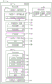
FIG. 1 is a block diagram of an embodiment of various components of an amusement park according to aspects of the present disclosure;
FIG. 2 is a schematic illustration of an embodiment of a ride system according to aspects of the present disclosure;
FIG. 3 is a flow chart of a process for controlling movement of a carrier housed in a ride carrier operating in the ride system of FIG. 2, in accordance with aspects of the present disclosure;
FIG. 4 is a schematic view of an embodiment of a platform assembly configured to support the bracket of FIG. 3, in accordance with aspects of the present disclosure;
FIG. 5 is a schematic illustration of an embodiment of the platform assembly of FIG. 4 and an alignment mechanism configured to align the carriage of FIG. 3 when supported by the platform assembly of FIG. 4, in accordance with aspects of the present disclosure;
FIG. 6 is a schematic view of an embodiment of the bracket of FIG. 3 supported by the platform assembly of FIG. 4 in accordance with aspects of the present disclosure;
FIG. 7 is a schematic view of an embodiment of the bracket of FIG. 3 receiving and securing the ride vehicle of FIG. 3 in accordance with aspects of the present disclosure;
FIG. 8 is a schematic diagram of an embodiment of a pulley system actuated to control movement of the carriage of FIG. 3 in accordance with aspects of the present disclosure;
FIG. 9 is a schematic diagram of an embodiment of the pulley system of FIG. 8 actuated to drive movement of the carriage of FIG. 3 to the platform assembly of FIG. 4 in accordance with aspects of the present disclosure;
FIG. 10 is a schematic diagram of an embodiment of the bracket of FIG. 3 having four pulley systems in an open loop configuration in accordance with aspects of the present disclosure;
FIG. 11 is a schematic diagram of an embodiment of the bracket of FIG. 3 having eight pulley systems in an open loop configuration in accordance with aspects of the present disclosure;
FIG. 12 is a schematic view of an embodiment of the bracket of FIG. 3 having four pulley systems in a closed loop configuration in accordance with aspects of the present disclosure;
FIG. 13 is a schematic diagram of an embodiment of the four pulley system of FIG. 12 driving movement of the carriage of FIG. 3 in accordance with aspects of the present disclosure;
FIG. 14 is a schematic view of an embodiment of the four pulley system of FIG. 12 raising the carriage of FIG. 3 in accordance with aspects of the present disclosure;
FIG. 15 is a schematic diagram of an embodiment of the four pulley system of FIG. 12 lowering the carriage of FIG. 3 in accordance with aspects of the present disclosure; and
fig. 16 is a schematic diagram of an embodiment of the four pulley system of fig. 12 stabilizing the carriage of fig. 3, in accordance with aspects of the present disclosure.
Detailed Description
One or more specific embodiments of the present disclosure will be described below. In an effort to provide a concise description of these embodiments, all features of an actual implementation may not be described in the specification. It should be appreciated that in the development of any such actual implementation, as in any engineering or design project, numerous implementation-specific decisions must be made to achieve the developers' specific goals, such as compliance with system-related and business-related constraints, which may vary from one implementation to another. Moreover, it should be appreciated that such a development effort might be complex and time consuming, but would nevertheless be a routine undertaking of design, fabrication, and manufacture for those of ordinary skill having the benefit of this disclosure.
While the following discussion is generally provided in the context of amusement park style rides that may include a plurality of closed or open loop pulley systems to drive movement of a carriage that may secure and house a ride carrier, it should be understood that the embodiments disclosed herein are not limited to such amusement environments. Indeed, examples and explanations are provided in such entertainment applications to facilitate explanations by providing examples of real-world implementations and applications. Accordingly, it should be appreciated that the embodiments disclosed herein may be useful in other applications such as transportation systems (e.g., railway systems, building and floor connection systems), elevator systems, and/or other industrial, commercial, and/or recreational human transportation systems, to name a few.
In view of the foregoing, the present embodiments include systems and methods for controlling movement of a ride vehicle operating within a ride system. For example, a ride system (such as the amusement park style ride referenced above) may include one or more ride vehicles that carry passengers along a ride path defined by a track, for example. During the ride, the ride path may include a number of features including tunnels, turns, upward, downward, loops, etc. For example, the direction of travel of the ride vehicle may be defined by the ride path, as the rollers of the ride vehicle may be in constant contact with the tracks defining the ride path. It may be desirable to control the vertical movement of the ride vehicle along a vertical axis. As used herein, "vertical motion" may refer to motion having a component oriented substantially parallel to the gravity vector. In some prior approaches in which the wheel assemblies of the ride vehicle are the only mechanism for driving movement of the ride vehicle along the track defining the ride path, such that the ride path has components oriented along a vertical axis, vertical movement may result in unwanted loads being experienced by the ride vehicle and/or the wheel assemblies. Furthermore, these existing methods may result in the occupant always being oriented in the same direction relative to the ride path, which may be undesirable because more complete control of the occupant's position and speed relative to the ride path may be desirable. Further, in these prior methods, the occupant may be aware that vertical movement is achieved via the ride vehicle continuing to move back and forth along the ride path (transition) such that the stimulus associated with the ride experience is compromised because the occupant visually anticipates movement of the ride vehicle.
According to certain embodiments of the systems and methods disclosed herein, the ride experience may be enhanced when the vertical movement of the ride vehicle is controlled. As an example, a mechanism is allowed that renders the vertical movement imperceptible to the passenger and the unwanted load on the ride vehicle is reduced and/or eliminated. Aspects of the disclosed embodiments include receiving a ride vehicle from a ride path and securing the ride vehicle to a bracket removably coupled to a platform assembly, as described in detail below. In embodiments, the brackets may seamlessly mate with the ride path (e.g., track of the ride path) to seamlessly receive the ride carrier and then secure the ride carrier. Further, after securely receiving the ride vehicle, the cradle (which receives the ride vehicle) may be separated from the platform such that the cradle is freely suspended relative to the platform, as discussed in detail below. In embodiments, the platform may, for example, retract, pivot about a point, or perform any suitable movement so as not to interfere with the movement of the carriage.
To allow for control of this movement of the carriage, the ride system may include a plurality of pulley systems, each comprising an actuatable motor to drive movement of a corresponding pulley coupled to the ride carrier to, in turn, collectively drive movement of the carriage. That is, the control system may receive ride system data (e.g., position, speed, acceleration along or about any of the longitudinal, lateral, and vertical axes for a moveable feature of the ride system) and actuate the motor to drive movement of the carriage, as described in detail below. The pulley system may be an open loop or closed loop control system. An "open loop" pulley system may refer to a pulley system employing a pulley cable having a first end that is separate from a second end. For example, the first end may be coupled to a bracket and the second end may be coupled to a winch or a wall. Further, a "closed loop" pulley system may refer to a pulley system employing pulley cables having a closed profile.
For pulley systems employing closed loop pulley cables, the brackets may always contact the same point on the closed loop pulley cable. In this way, actuating the motor to drive the corresponding closed loop pulley cable in rotation causes the carriage to be driven in motion because the motion of the carriage may be based on the motion of the closed loop pulley cable. For example, the carriage may be coupled to four pulleys, each pulley passing through the carriage (e.g., an inner surface of the carriage) and including portions oriented substantially parallel to each other and oriented along a vertical axis. Thus, control instructions (e.g., control signals) from the control system that actuate the motor to drive movement of the pulley cable may also control movement of the carriage.
To aid in the description, fig. 1 is a block diagram of an embodiment of various components of amusement park 8 according to aspects of the present disclosure. Amusement park 8 may include ride system 10, including ride path 12, ride path 12 receiving and guiding ride vehicle 20, such as by engaging tires or rollers of ride vehicle 20, and facilitating movement of ride vehicle 20 (e.g., through a scenic spot). In this manner, the ride path 12 may define a track and direction of travel, which may include turns, ramps, downdips, upward, downward, slopes, loops, and the like. In embodiments, the ride vehicle 20 may be driven passively or actively via a pneumatic system, a motor system, a tire drive system, a roller system, a fin (fin) coupled to an electromagnetic drive system, an ejection system, or the like.
The ride path 12 may receive more than one ride vehicle 20. The ride carriers 20 may be separate from each other such that they are independently controlled, or the ride carriers 20 may be coupled to each other via any suitable linkage such that movement of the ride carriers 20 is coupled or linked. For example, a front portion of one ride vehicle 20 may be coupled to a rear end of another ride vehicle 20. Each ride vehicle 20 in these and other configurations may support one or more passengers 22. In an embodiment, the ride vehicle 20 may include a turntable, yaw drive system, or any experience enhanced motion-based platform that allows movement of the passenger cabin relative to the chassis of the ride vehicle 20.
The ride system 10 may include a cradle 24 that may receive one or more ride carriers 20. In one non-limiting embodiment, the shape of the carrier 24 may substantially match the shape of the ride vehicle 20 to facilitate receiving and securing the ride vehicle 20. For example, the ride vehicle 20 may have a substantially rectangular prismatic profile, and the brackets 24 may have a similar substantially rectangular prismatic profile that is larger in size to receive and accommodate the ride vehicle 20. While the shape of the ride vehicle 20 and the carriages 24 are discussed as having a substantially rectangular prismatic profile, it should be understood that the ride vehicle 20 and carriages 24 may individually have any other suitable shape and size.
The ride carrier 20 may be driven in motion along the ride path 12 via rollers of a roller system, and the carriages 24 may seamlessly cooperate with the ride path 12 to receive the rollers. In this manner, the bracket 24 may also define the ride path 12 when mated. The occupant may not feel or experience the substantially vertical displacement resulting from the transition of the ride vehicle 20 from the ride path 12 (e.g., the track defining the ride path 12) to the carriages 24 because the ride rollers may seamlessly transition from the ride path 12 to the carriages 24. While certain embodiments of the ride path 12 are disclosed as having tracks, it should be understood that the tracks may be omitted such that the ride path 12 may include a surface upon which the ride carriers 20 (e.g., autonomous ride carriers) may reciprocate.
To facilitate such a seamless transition, the carrier 24 may include a stop device 26 that slows the ride vehicle 20, and may include a fastening device 28 that secures the ride vehicle 20 to the carrier 24 after the ride vehicle 20 has slowed to a stop. In an embodiment, the fastening means 28 may comprise or also function as the stopping means 26, such that the fastening means 28 is integral with the stopping means 26. The stopping device 26 may include a dead end stop pin, a damper, a spring system, a brake pad system, and/or any suitable device configured to slow the ride vehicle 20 to a target position on the carriage 24. The securing device 28 may include a hook, a ratchet system, a redundant locking mechanism, or any suitable device for locking the ride vehicle 20 in place, thereby allowing the ride vehicle 20 to become stationary relative to the carriage 24 at a target location on the carriage 24. As can be appreciated, the ride vehicle 20 may be fixed relative to the brackets 24 when the securing means 28 (and stopping means 26) are engaged. Alternatively, the ride vehicle 20 may be free to exit (or enter) the carrier 24 when the fastening means 28 (and stopping means 26) are disengaged. For example, the ride carrier 20 may exit the carriages 24 to continue traveling along the ride path 12. As discussed in detail below, the ride path to which the ride vehicle 20 exits may or may not be the same as the ride path from which the ride vehicle 20 is received from the cradle 24.
When the carrier 24 receives the ride vehicle 20, the carrier 24 may be supported by the platform assembly 32. The carriage 24 may be removably coupled to the platform assembly 32 such that the carriage 24 may be decoupled from the platform assembly 32 for movement relative to the platform assembly 32, as described in detail below. In an embodiment, the bracket 24 may be separated from the platform assembly 32 after the verification fastening device 28 (and/or the stop device 26) is engaged and/or after the verification ride vehicle 20 is fastened to the bracket 24. Verification of engagement of the fastening device 28 and/or the stopping device 26 is described in more detail below. In an embodiment, movement of the brackets 24 may occur in response to verifying that the ride vehicle 20 is secured to the brackets 24. In this way, the ride vehicle 20 (which is secured and received by the carriage 24) and the carriage 24 may move together as a single object (e.g., as a multi-DOF elevator).
Movement of the carriage 24 and ride vehicle 20 may be accomplished via one or more pulley systems 34. For example, the pulley systems 34 may each include a motor 36, and the motor 36 may drive movement of the pulley cable 38. Further, pulley system 34 may be coupled to carriage 24 in any suitable configuration. In an embodiment, the four pulley systems 34 may each include pulley cables 38 positioned parallel to each other and coupled to an inner surface of the carriage 24 such that the pulley cables 38 may be independently driven by the corresponding motors 36. Although movement of the carriage as discussed in this example is achieved via four pulley systems 34, it should be understood that any suitable number of pulley systems 34, such as one, two, three, five, ten pulley systems, may be employed to control movement of the carriage. Pulley system 34 may be in any suitable configuration and include open loop or closed loop cables.
The control system 50 may be communicatively coupled to one or more ride vehicles 20 of the amusement park 8 via any suitable wired and/or wireless connection (e.g., via a transceiver). The control system 50 may control the position of the carriage 24 by actuating the motor 36 to drive the movement of the pulley cable 38 to control various aspects of the ride system 10, such as the direction of travel of the ride carrier 20 in some portion of the ride implementation. The control system 50 may receive data from sensor assemblies 51 associated with the ride system 10, for example, to control the position and speed of each of the pulley cables 38. In an embodiment, the control system 50 may be an electronic controller having circuitry configured to process data associated with the ride system 10, for example, from the sensor assembly 51 via a transceiver. Further, the control system 50 may be coupled to various components of the amusement park 8 (e.g., park attractions, park controllers, and wireless networks).
The control system 50 may include a memory circuit 52 and a processing circuit 54, such as a microprocessor. The control system 50 may also include one or more storage devices 56 and/or other suitable components. The processing circuitry 54 may be used to execute software, such as software stored on the memory circuitry 52 for controlling the ride carrier(s) 20 and any components associated with the ride carrier 20 (e.g., the carriage 24, the stop 26, the fastening device 28, the platform assembly 32, and the pulley system 34). Further, the processing circuitry 54 may include a plurality of microprocessors, one or more "general purpose" microprocessors, one or more special purpose microprocessors, and/or one or more Application Specific Integrated Circuits (ASICs), or some combination thereof. For example, the processing circuitry 54 may include one or more Reduced Instruction Set (RISC) processors.
The memory circuit 52 may include volatile memory, such as Random Access Memory (RAM), and/or non-volatile memory, such as Read Only Memory (ROM). The memory circuit 52 may store a variety of information and may be used for a variety of purposes. For example, the memory circuit 52 may store processor-executable instructions (e.g., firmware or software) for execution by the processing circuit 54, such as instructions for controlling components of the ride system 10. For example, the instructions may cause the processing circuit 54 to control the movement of the carriage 24 by actuating the motor 36 to drive the movement of the pulley cable 38 to subject the occupant 22 to a ride-enhancing movement, while also controlling the turntable or yaw drive system to further enhance the overall ride experience by subjecting the occupant to additional movement.
The storage device(s) 56 (e.g., nonvolatile storage) may include ROM, flash memory, hard disk drive, or any other suitable optical, magnetic, or solid state storage medium or combination thereof. The storage device(s) 56 may store ride system data (e.g., passenger information, data associated with amusement park 8, data associated with ride path trajectories), instructions (e.g., software or firmware for controlling the carriages 24, platform assemblies 32, pulley systems 34, and/or ride vehicles 20), and any other suitable information.
The ride system 10 may additionally or alternatively include a ride environment 60, and the ride environment 60 may include multiple and different combinations of environments. The ride environment 60 may include a type of ride (e.g., a dark ride, a water roller coaster, a virtual reality [ VR ] experience, or any combination thereof) and/or associated characteristics (e.g., theme) of the type of ride. For example, the ride environment 60 may include aspects of the ride system 10 that add to the overall theme and/or experience associated with the ride system 10.
The ride system 10 may additionally or alternatively include a motion-based environment 62 in which the occupant 22 is transported or moved by the ride system 10. For example, the motion-based environment 62 may include a flat ride 64 (e.g., a ride such as by the ride vehicle 20 traveling along the ride path 12 toward the carriages 24, moving the occupant 22 substantially in a plane generally aligned with the ground). Additionally or alternatively, the motion-based ride environment 62 may include a gravity ride 66 (e.g., a ride in which the motion of the occupant 22 has at least a component along a gravity vector, such as a motion generated via the pulley system 34 acting on the carriage 24). Additionally or alternatively, the motion-based ride environment 62 may include a vertical ride 68 (e.g., a ride that displaces the occupant 22 in a vertical plane about a fixed point, such as a motion generated via the pulley system 34 acting on the carriage 24).
The ride system 10 may additionally or alternatively include a stationary environment 70 in which the occupant 22 is not substantially transported or displaced by the ride system 10. For example, the stationary environment 70 may include a virtual reality (V/R) feature 72 (e.g., the occupant 22 may sit in a vibrating or stationary seat while wearing a virtual reality (V/R) headset (head set) that displays the VR environment or experience) and/or a different kind of simulation 74. In an embodiment, the ride vehicle 20 may stop along the ride path 12 such that the ride experience may include aspects of the stationary ride environment 70 for a portion of the duration of the ride experience. While the stationary environment 70 may not substantially move the occupant 22, the virtual reality and/or simulation effect may modify the perception of the occupant 22, which may be enhanced and contrasted by the motion-based distortion experienced by the occupant 22. To this end, it should be appreciated that the ride system 10 may include both a motion-based ride environment 62 and a stationary ride environment 70, which make the brackets 24 and pulley system 34 desirable features, at least for enhancing the ride experience.
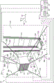
FIG. 2 is a schematic illustration of an embodiment of a ride system 10 according to aspects of the present disclosure. The ride system 10 may include a plurality of ride vehicles 20 coupled together via linkages to add passengers 22 riding in the corresponding ride vehicles 20 to a common ride experience. In embodiments, the ride carriers 20 may be decoupled from one another and may alternatively be movable independently of one another, e.g., along respective and/or separate ride paths 12. In another embodiment, the ride vehicles 20 may move as a group.
For example, a first group 20A of ride carriers 20 (e.g., three ride carriers) may move along a first ride path 12A, and a second group 20B of ride carriers 20 (e.g., five ride carriers) may move along a second ride path 12B. The first ride path 12A may be at a level positioned higher than the second ride path 12B. For example, the first ride path 12A may define a direction of travel of the ride vehicle 20 operating in a level above the second ride path 12B. The carriages 24 may receive the ride carriers 20 individually or as groups (e.g., first or second groups 20A, 20B) to transport the ride carrier(s) 20 from along the first ride path 12A to the second ride path 12B or from any ride path 12 to any other ride path 12.
The control system 50 may instruct the carriages 24 to be vertically displaced to transport the ride carrier 20 from the first ride path 12A on a first level to the second ride path 12B on a second (e.g., lower) level. Alternatively, the control system 50 may instruct the carriages 24 to be vertically displaced to transport the ride vehicle 20 from the first ride path 12A on a first level to the second ride path 12B on a second (e.g., lower) level and back to the first level so that the ride vehicle 20 may continue to move along the first ride path 12A. By employing the embodiments disclosed herein, the control system 50 can displace the carriage 24 in a ride-enhancing manner to, in embodiments, change the direction of travel (e.g., from along the first ride path 12A to the second ride path 12B). The brackets 24 may displace the passengers 22 by subjecting the passengers to experience-enhancing motions described in detail below, while enhancing their riding experience. It should be appreciated that the control system 50 may instruct the ride vehicle 20 to travel along the ride path 12 in any desired manner.
Fig. 3 is a flow chart of a process 80 for controlling movement of a carrier 24 (fig. 1, 2) housed in a ride vehicle 20 (fig. 1, 2) operating in the ride system 10 of fig. 2, in accordance with aspects of the present disclosure. Process 80 may be implemented by seating system 10. In a non-limiting embodiment, processor-based circuitry of control system 50 (fig. 1, 2) may facilitate implementation of process 80. In view of the foregoing, the control system 50 may position (process block 82) the ride vehicle 20 on the carrier 24 (fig. 1, 2) at a target location on the carrier 24. The control system 50 may actuate the stop device 26 (fig. 1) to cause the ride vehicle 20 to stop at a position on the carrier 24 in which the ride vehicle 20 may be engaged with the fastening device 28 (fig. 1). For example, the target location may be a location on the carrier 24 where the fastening device 28 may engage a compatible feature (e.g., a female or male connector) of the ride vehicle 20.
The control system 50 may receive (process block 83) ride system data from the sensor assemblies 51 associated with the ride system 10 (fig. 1, 2) before, during, or after controlling movement of the carriage 24. In this way, the control system 50 may receive ride system data, such as: the position, speed, and acceleration of the ride vehicle 20, the engagement status (e.g., engaged or disengaged) of the stop device 26 and the fastening device 28, the position, speed, or acceleration of the pulley cable 38 and/or the motor 36, the engagement status of the carriage 24 relative to the platform assembly 32, the position of the platform assembly 32, etc., to facilitate controlling features in the ride system 10. Control instructions sent from the control system 50 to the various features of the amusement park 8 may be based on ride system data, subsets of ride system data, and/or any additional data.
The control system 50 may secure (process block 84) the ride vehicle 20 to the cradle 24 based on the ride system data. After verifying that the ride vehicle 20 is properly positioned on the carrier 24, the control system 50 may engage the securing device 28 to secure (process block 84) the ride vehicle 20 into the carrier 24. For example, after verifying that the ride vehicle 20 is stopped and positioned at the target location on the carrier 24, the control system 50 may engage the fastening device 28 to fasten the ride vehicle to the carrier 24 such that the ride vehicle 20 becomes secured to the carrier (e.g., at one or more connection points). The fastening device 28 may include a number of mechanisms to redundantly fasten the ride vehicle 20 to the brackets 24. For example, the fastening device 28 may fasten (process block 84) the ride carrier 20 to the floor of the bracket 24, to the sides of the bracket 24, to the ceiling of the bracket 24, or any combination thereof, among any additional suitable locations on the bracket 24. In this manner, movement of the ride vehicle 20 and the carriages 24 may be coordinated such that the ride vehicle 20 and carriages 24 may operate as a single feature (e.g., a multi-DOF elevator).
To control movement of the carriage 24, the control system 50 may actuate (process block 86) the motor 36 corresponding to each pulley system 34, as described in detail below. Each motor 36 may be communicatively coupled to the control system 50 such that the control system 50 may control each motor 36 to drive movement of the corresponding pulley cable 38. In an embodiment, the control system 50 may supply electrical power (e.g., AC or DC current) to drive movement of the corresponding pulley cable 38 to in turn drive movement of the carriage 24. In an embodiment, the carriage 24 may be coupled to the pulley cable 38 such that when the control system 50 drives movement of the pulley cable 38, the corresponding portion of the carriage 24 coupled to the pulley cable 38 is displaced in a substantially similar manner. For example, for a carriage 24 coupled to four pulley cables 38 at each of the four portions of the carriage, the control system 50 may control the movement of each of the four portions of the carriage 24 by actuating the motor 36 to drive the pulley cable 38 in motion based on ride data.
In an embodiment, the bracket 24 may be removably coupled to the platform assembly 32 (fig. 1) such that the platform assembly 32 may include a fastening mechanism that fastens the bracket 24 to the platform assembly 32. In response to actuation of the motor 36, the control system 50 may disengage the fastening devices on the platform assembly 32 to allow movement of the carriage 24 relative to the platform assembly 32, as described in detail below.
After activating the motor 36 and causing the carrier 24 to perform the stimulation enhancement motion, the control system 50 may stop the motion of the carrier 24 and position the carrier 24 on the platform assembly 32 and/or secure the carrier 24 to the platform assembly 32 to allow (process block 88) the ride carrier 20 to exit the carrier 24. Prior to allowing exit from the ride vehicle 20, the control system 50 may verify that the carriages 24 and ride path 12 cooperate in such a manner that: the ride vehicle 20 may seamlessly transition from the carrier 24 to the ride path 12. Additionally or alternatively, the control system 50 may verify that the carrier 24 is secured to the platform assembly 32 before allowing (process block 88) the ride vehicle 20 to exit from the carrier 24. In an embodiment, the ride path 12 onto which the ride vehicle 20 may exit may not be the same as the ride path 12 from which the ride vehicle 20 may have entered. Thus, in an embodiment, the carriage 24 may transport the ride carrier to another ride path.
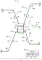
FIG. 4 is a schematic illustration of an embodiment of a platform assembly 32 configured to support the carriage 24 of FIG. 3, in accordance with aspects of the present disclosure. To facilitate discussion, a coordinate system is illustrated that includes a longitudinal axis 90, a lateral axis 92, and a vertical axis 94 (e.g., oriented parallel to a gravity vector). The platform assembly 32 may include one or more bracket members 95 to support a platform base 96. The bracket member 95 may be secured to a rod member 97 that extends along the width of the platform base 96.
In the illustrated embodiment, the platform base 96 may extend outwardly from the vertical rail 98 along the longitudinal axis 90. When the bracket 24 is supported by the platform assembly 32, the bracket 24 may be positioned on the platform base 96. The platform base 96, the bracket members 95, and the rod members 97 may be fabricated from any material (e.g., steel alloy, copper, aluminum) configured to support at least the weight of the carrier 24, the occupant 22 (fig. 1, 2), and one or more ride carriers 20 housed within the carrier 24. Further, while the depicted platform base 96 is quadrilateral in shape, the platform base 96 may have any suitable shape (e.g., circular, triangular, rectangular, octagonal, or arcuate) that may support the carrier and one or more ride carriers 20.
The platform assembly 32 may include vertical rails 98 that allow the platform base 96 to transport the platform base 96 along the vertical axis 94. For example, the platform assembly 32 may include a plurality of rollers 100, the rollers 100 engaging the vertical rail 98 and rotating about the lateral axis 92 to drive vertical movement of the platform base 96. Movement of the platform base 96 may be accomplished via a motor 102 communicatively coupled to the control system 50 such that the motor 102 may receive control instructions to drive vertical movement of the platform base 96. In an embodiment, the motor 102 may receive control instructions from the control system 50 to control the current or voltage supplied to the vertical rail 98 to drive the rotation of the roller 100 and the movement of the platform base 96. In another embodiment, the motor 102 may receive control instructions from the control system 50 to control a winch 104, which may drive the movement of a pulley cable 106 coupled to the platform base 96. The platform assembly 32 may include a counterweight 108, and the counterweight 108 may reduce the force required to control the vertical movement of the platform base 96. Although the movement of the platform base 96 is discussed as being driven via a motor system using the motor 102, the platform assembly 32 may include a pneumatic system, a motor system, a tire drive system, fins coupled to an electromagnetic drive system, an ejection system, etc., to actively or passively drive the platform base 96. Further, the motor 102 may be integral or incorporated into the winch 104.
Fig. 5 is a schematic illustration of an embodiment of the platform assembly 32 of fig. 4 and an alignment mechanism 110 configured to align the carriage 24 of fig. 3 when supported by the platform assembly 32 of fig. 4, in accordance with aspects of the present disclosure. Alignment mechanism 110 may include alignment pins 112 on platform base 96 and openings 114 on the lower surface of bracket 24 such that each alignment pin 112 may engage with a corresponding opening 114. Alignment pin 112 may have a tapered profile extending vertically upward from platform base 96 along vertical axis 94, and corresponding opening 114 may have a similar profile that engages alignment pin 112. The tapered profiles of alignment pins 112 and openings 114 may cooperate with one another to facilitate placement of carrier 24 on platform assembly 32. Alignment mechanism 110 may facilitate maintaining contact between platform base 96 and carrier 24 and preventing carrier 24 from sliding or rotating away from platform assembly 32 (e.g., by rotating about vertical axis 94, longitudinal axis 90, and lateral axis 92).
Further, the platform assembly 32 may include a rear stabilizer 116, the rear stabilizer 116 including a raised surface having a height 118 that rises vertically upward from the top of the platform base 96. The height 118 may be substantially similar in size to the thickness 120 of the base of the bracket 24. In this manner, the rear stabilizer 116 may facilitate the transition of the ride vehicle 20 from the ride path 12 to the carriages 24. For example, upon transitioning from the ride path 12 (fig. 1, 2) to the carriages 24, the ride vehicle 20 (fig. 1, 2) may travel from the ride path 12 to the rear stabilizer 116 and onto the carriages 24. It should be appreciated that in another embodiment, the rear stabilizer 116 may be omitted such that the top thickness 120 is flush with the ride path 12 to facilitate a seamless transition of the ride carrier 20.
Although not shown, a fastening mechanism that fastens the bracket 24 to the platform assembly 32 (e.g., to the platform base 96) may be positioned on the platform base 96 and enhanced by the alignment mechanism 110. In an embodiment, the securing mechanism of the platform assembly 32 may be integral with the alignment mechanism 110.
FIG. 6 is a schematic diagram of an embodiment of the bracket 24 of FIG. 3 supported by the platform assembly 32 of FIG. 4, in accordance with aspects of the present disclosure. The ride system 10 may include two level rides, which may include a first ride path 12A, which first ride path 12A may be positioned at a higher level than a second ride path 12B. The ride system 10 may include eight pulley systems 34, each communicatively coupled to a control system 50, such that the control system 50 may control the pulley cable 38 to control movement of the carriage 24. As illustrated, eight pulley cables 38 may be coupled to respective edges of the carriage 24, but it should be understood that any number of pulley cables 38 may be coupled to any location on the carriage 24. The pulley cable 38 may be pre-tensioned such that all eight cables are similar in length.
As illustrated, the carrier 24 may remain rigidly secured to the platform assembly 32 while the carrier 24 receives or waits to receive and secure one or more of the ride carriers 20. For example, the fastening mechanism of the platform assembly 32 may rigidly secure the bracket 24 to the platform to limit movement of the bracket 24 relative to the platform assembly 32. Further, while the carrier 24 receives or waits to receive and secure the ride vehicle 20, the platform assembly 32 may remain fixed in position (e.g., in response to certain control instructions, responses from the motor 102, and/or assistance from the counterweight 108) such that vertical movement of the platform assembly 32 is limited. Alternatively or additionally, the control system 50 may actuate the motor 36 (fig. 1) corresponding to each pulley system 34 to pull each pulley cable 38 in a corresponding outward direction 122. In this manner, the load exerted by the carriage 24 on the platform assembly 32 may decrease with the tension in the pulley cable 38, which may suspend or partially suspend the carriage 24.
Fig. 7 is a schematic view of an embodiment of the carrier 24 of fig. 3 receiving and securing the ride vehicle 20 of fig. 3 in accordance with aspects of the present disclosure. The occupant 22 (fig. 1, 2) may be kept partially unaware of the ride path 12 (e.g., the first ride path 12A and the second ride path 12B) by the wall 124. For example, in an embodiment, the motor 36 corresponding to the pulley cable 38 may be hidden behind the wall such that a mechanism is maintained that renders the motion of the pulley cable 38 imperceptible to the occupant 22. Additionally, after the ride vehicle 20 exits the ride path 12, the door may be raised or swung closed from horizontal to further obscure the ride path 12 from the occupant 22.
The control system 50 may direct movement of the ride carrier 20 along the longitudinal direction 90 via the first ride path 12A and engage the stop device 26 (fig. 1) and the fastening device 28 (fig. 1) in response to determining (e.g., via the sensor assembly 51) that the ride carrier 20 is stopped at a target location on the bracket 24 and fastened to the bracket 24. After verifying that the ride vehicle 20 is secured to the carriage 24, the control system 50 may send control instructions to the platform assembly 32 to disengage the securing mechanism to allow the carriage 24 to be moved via actuation of the pulley system 34. For example, the control system 50 may send control instructions to each of the pulley systems 34 to control movement of the carriages 24 (and the secured ride carriers 20), as described in detail below.
To aid in the description, fig. 8 is a schematic diagram of an embodiment of a pulley system 34 actuated to control movement of the carriage of fig. 3 in accordance with aspects of the present disclosure. The control system 50 may send control instructions to the upper pulley system (e.g., pulley systems 34A, 34B, 34C, 34D) such that the corresponding motor 36 (not shown) of fig. 1 causes the upper pulley cable to apply a greater force than the lower pulley cable (e.g., pulley cables 38E, 38F, 38G, 38H) to lift the carriage 24 from the platform assembly 32. For example, the motor 36 corresponding to the upper pulley cable may cause the upper pulley cable to retract in the outward direction 122 to lift the carriage 24 off of the platform assembly 32. While lifting the carriage 24, the lower pulley cable may be free to extend (move opposite the outward direction 122) to facilitate upward movement of the carriage 24, such as by free rotation about a corresponding winch.
In an embodiment, the control system 50 may control the movement of the carriage 24 by controlling an input (e.g., a current input) to the movement of the drive pulley cable 38 of the motor 36. In this manner, the control system 50 may control movement of the carriage 24 by retracting or extending the pulley cable 38 to a target position and/or retracting or extending at a target speed. To achieve this control of the pulley cable 38, the control system 50 may receive ride system data from the sensor assembly 51 (fig. 1) to control the pulley cable 38 individually or as a group. For example, as illustrated, the leftmost pulley cable (e.g., pulley cable 38A, 38B, 38E, 38F) may retract in an outward direction 122 in response to their corresponding motor 36, causing the leftmost pulley cable to exert a pulling force on the carriage 24. As can be appreciated, the pulley cable 38 can be controlled to control movement of the carriage 24 along or about the longitudinal axis 90, the transverse axis 92, and/or the vertical axis 94.
After decoupling bracket 24 from platform assembly 32, platform base 96 may be lowered flush with second ride path 12B. As described above, the platform base 96 may be lowered, for example, by actuating the motor 102 until the rear stabilizer 116 is flush with the second ride path 12B, to facilitate egress of the ride vehicle from the cradle 24. In another embodiment, without the rear stabilizer 116, the platform base 96 may be lowered until the base of the carriage 24 is flush with the second ride path 12B to facilitate egress of the ride vehicle from the carriage 24 onto the second ride path 12B.
Fig. 9 is a schematic diagram of an embodiment of the pulley system 34 of fig. 8 actuated to drive movement of the carriage 24 of fig. 3 to the platform assembly 32 of fig. 4, in accordance with aspects of the present disclosure. The control system 50 may control the pulley system 34 such that the control system 50 controls movement of the pulley cable 38 such that the carriage 24 is positioned above the platform assembly 32 and lowered to the platform assembly 32. After positioning the bracket 24 over the platform assembly 32, the fastening mechanism of the platform assembly 32 may be engaged to fasten the bracket 24 to the platform assembly 32. After verifying that the carrier 24 is secured to the platform assembly 32, the control system 50 may instruct the ride carrier 20 to exit the carrier 24 onto the second ride path 12B.
Fig. 10 is a schematic diagram of an embodiment of the carriage 24 of fig. 3 having four pulley systems 34 in an open loop configuration in accordance with aspects of the present disclosure. To facilitate discussion, the ride system 10 is illustrated in the embodiment of fig. 10-16, with some of the foregoing features omitted. However, it should be appreciated that the embodiments of fig. 10-16 may include a platform assembly 32, a wall 124, and one or more ride paths 12 such that the carriage 24 may receive the ride vehicle 20 from the first ride path 12A and/or transport the ride vehicle to the second ride path 12B (or vice versa) after performing the stimulus-enhanced motion, and allow the ride vehicle 20 to continue moving along either the first or second ride paths based on instructions from the control system 50. As described above, the instructions from the control system 50 may be based on ride data from, for example, the sensor assembly 51 (fig. 1) used to determine the ride data.
Further, in the embodiment of fig. 10 and 11, the control system 50 may actuate devices in the ride system 10 to cause the ride vehicle 20 to perform five DOF movements; for example, heave motion (e.g., motion along the vertical axis 94), pitch motion (e.g., motion about the lateral axis 92), roll motion (e.g., motion about the longitudinal axis 90), pitch (e.g., motion along the longitudinal axis 90), and yaw motion (e.g., motion along the lateral axis 92). In the embodiment of fig. 12-16, the control system 50 may actuate devices in the ride system 10 to cause the ride vehicle 20 to perform three DOF motions; such as heave motions (e.g., motions along the vertical axis 94), pitch motions (e.g., motions about the lateral axis 92), and roll motions (e.g., motions about the longitudinal axis 90). However, it should be appreciated that passengers may experience six DOF motion in response to the control system 50 additionally actuating a device (e.g., a turntable, yaw drive system, or any motion-based platform that experiences enhanced) of the ride vehicle 20.
The pulley system 34 (e.g., pulley systems 34A, 34B, 34C, 34D) may receive control instructions from the control system 50 to drive the corresponding motor 30 (e.g., motors 30A, 30B, 30C, 30D) in rotation to retract or extend the corresponding pulley cable 38. As illustrated, the origin of the pulley cable 38 on the bracket 24 extends outward (e.g., in the outward direction 122) from the contact point 125 on the bracket 24 to facilitate movement along the longitudinal axis 90, along the lateral axis 92, along the vertical axis 94, about the longitudinal axis 90, and/or about the lateral axis 92.
To further facilitate this movement, upper pulley cables (e.g., pulley cables 38A, 38B) and lower pulley cables (e.g., pulley cables 38C, 38D) may be positioned on the bracket 24 at corners opposite each other, respectively. For example, in an embodiment, two upper cables are positioned on opposite corners of the top of the bracket 24 and two lower cables are positioned on opposite corners of the bottom of the bracket 24 such that the two upper cables are on different corresponding corners than the corners on which the two lower cables are coupled. While the pulley cable 38 having an open loop configuration in the illustrated embodiment of fig. 10 includes four pulley systems 34, it should be understood that the carriage 24 may include any number of pulley cables 38 having an open loop configuration. To aid in the description, fig. 11 is a schematic diagram of an embodiment of the carriage 24 of fig. 3 having eight pulley systems 34 in an open loop configuration in accordance with aspects of the present disclosure. Alternatively or additionally, the pulley system 34 may be arranged in a closed loop configuration.
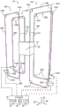
To this end, fig. 12 is a schematic illustration of an embodiment of the carriage 24 of fig. 3 having four pulley systems 34 in a closed loop configuration in accordance with aspects of the present disclosure. As described above, the carriage 24 may contact the same point on the pulley cable 38 during the duration of the ride. In this manner, one of the motors 30 is actuated to drive the corresponding pulley cable 38 in rotation to cause the carriage 24 to be driven in motion, as the motion of the carriage 24 may be based on the motion of the pulley cable 38. To facilitate discussion, ride system 10 includes a first pulley system 34A having a first motor 30A, a first set of winches 140A, and a first pulley cable 38A; a second pulley system 34B having a second motor 30B, a second set of winches 140B, and a second pulley cable 38B; a third pulley system 34C having a third motor 30C, a third set of winches 140C, and a third pulley cable 38C; and a fourth pulley system 34D having a fourth motor 30D, a fourth set of winches 140D, and a fourth pulley cable 38D.
The bracket 24 may be coupled to a plurality (e.g., four) of closed loop pulley cables 38 that each pass through the bracket 24 such that the pulley cables 38 are imperceptible to the occupant 22 (fig. 1, 2). The pulley systems 34 may each be associated with a plurality (e.g., four) of winches 140 that may be freely rotated to effect translation of the pulley cable 38. In an embodiment, one of the winches 140 of each pulley system 34 may be a drive winch (e.g., including the motor 30). As illustrated, the pulley cable 38 may be arranged in a quadrilateral configuration with a winch 140 on each edge of the quadrilateral configuration. The pulley cable 38 may include portions 142 oriented substantially parallel to each other and to the vertical axis 94. Control commands that cause the motor 30 to actuate and drive movement of the pulley cable 38 may also control movement of the carriage 24 in accordance with the control commands. Due to the substantially parallel arrangement of the portions 142 of the pulley cable 38 in contact with the carriage 24, the vertical movement of the carriage 24 may be better controlled, for example, because the pulley cable 38 contacts the carriage 24 at four contact points 125 extending the height of the carriage 24 (e.g., contact points 125 at each corner of the top surface of the carriage 24), and the pulley cable 38 may be parallel to each other at the respective portions 142.
In one embodiment, each of the four pulley cables 38 may extend between the top and bottom surfaces of the bracket at different portions of the bracket such that the four pulley systems 34 remain hidden from the occupant 22. In this configuration, pulley cable 38 may be rigidly secured to the inner surface of bracket 24 via any suitable mechanism (such as a clamp, ratchet system, etc.). In this manner, each pulley cable 38 may be driven in motion to drive a corresponding portion of the carriage 24, controlling the vertical movement, roll and pitch of the carriage 24 in a similar motion, as described in detail below.
As can be appreciated, the carriages 24 may receive the ride carriers 20 (fig. 1, 2) from the ride path 12 (fig. 1, 2) oriented along the longitudinal axis 90 or the transverse axis 92. However, the carrier 24 may receive the ride vehicle 20 from any suitable direction. After receiving and securing the ride vehicle 20, the carriages 24 may be controlled to move vertically (e.g., along a vertical axis 94), about a longitudinal axis 90, or about a lateral axis 92.
To aid in the description, fig. 13-16 each include an embodiment of a control system 50 that controls movement of the carriage 24 by causing the motor 30 to drive its corresponding pulley cable 38 in motion. For example, fig. 13 is a schematic diagram of an embodiment of the four pulley system 34 of fig. 12 driving movement of the carriage 24 of fig. 3 in accordance with aspects of the present disclosure. In the embodiment illustrated in fig. 13, the portion 142 of the second pulley cable 38B may be raised in response to the second motor 30B to cause the second set of winches 140B to rotate in the first rotational direction 150 (e.g., counterclockwise), thereby raising the corner of the bracket 24 coupled to the second pulley cable 38B. Additionally, the portion 142 of the third pulley cable 38C may be lowered in response to the third motor 30C to cause the third set of winches 140C to rotate in the first rotational direction 150, thereby lowering the corner of the bracket 24 coupled to the third pulley cable 38C.
Fig. 14 is a schematic diagram of an embodiment of the four pulley system 34 of fig. 12 raising the carriage 24 of fig. 3 in accordance with aspects of the present disclosure. In the embodiment illustrated in fig. 14, the first and second motors 30A, 30B may cause the first and second sets of capstans 140A, 140B to rotate in a first rotational direction 150, and the third and fourth motors 30C, 30D may cause the third and fourth capstans 140C, 140D to rotate in a second rotational direction 152 (e.g., clockwise), causing the carriage 24 to move along the vertical axis 94 based on the control instructions. In addition to or instead of causing vertical movement of the carriage by causing the winch to rotate at a different rate or causing the pulley cable to vertically displace at a different rate, the control system 50 may also cause rotation of the carriage 24 about the longitudinal axis 90 and the transverse axis 92.
For example, as illustrated, the carriage 24 may rotate about the transverse axis 92 in response to the control system 50 directing the first and third motors 30A, 30C to cause the first and third sets of capstans 140A, 140C to rotate at a higher rate than the second and fourth sets of capstans 140B, 140D. Similarly, as illustrated, the carriage 24 may rotate about the lateral axis 92 in response to the control system 50 directing the first and third motors 30A, 30C to cause the portions 142 of the first and third pulley cables 38A, 38C to vertically displace at a rate that is higher than the rate of displacement of the portions 142 of the second and fourth pulley cables 38.
To further aid in the description, fig. 15 is a schematic diagram of an embodiment of the four pulley system 34 of fig. 12 lowering the carriage 24 of fig. 3 in accordance with aspects of the present disclosure. As illustrated, the carriage 24 may be lowered in response to the control system 50 directing the first and second motors 30A, 30B to cause the first and second sets of winches 140A, 140B to rotate in the second rotational direction 152 and directing the third and fourth motors 30C, 30D to cause the third and fourth sets of winches 140C, 140D to rotate in the first rotational direction 150. Similarly, the carriage 24 may be lowered in response to the control system 50 directing the motor 30 to cause the portion 142 of the pulley cable 38 to displace downward.
As can be appreciated, when the pulley cable 38 is displaced at the same rate and/or when the winch 140 is rotated at the same rate, the carriage 24 can translate vertically without substantial rotation about the longitudinal axis 90, the transverse axis 92, and the vertical axis 94. To help illustrate this vertical translation of the carriage 24, fig. 16 is a schematic diagram of an embodiment of the four pulley system 34 of fig. 12 stabilizing the carriage 24 of fig. 3 in accordance with aspects of the present disclosure.
Although only certain features of the disclosed embodiments have been illustrated and described herein, many modifications and changes will occur to those skilled in the art. It is, therefore, to be understood that the appended claims are intended to cover all such modifications and changes as fall within the true spirit of the disclosure.
The techniques presented and claimed herein are referenced and applied to material objects and specific examples of practical nature that may prove to improve upon the art and are therefore not abstract, intangible, or purely theoretical.
Claims (21)
1. A ride system for controlling movement of a ride vehicle, the ride system comprising:
a bracket configured to receive and secure the ride vehicle; and
a plurality of pulley systems drivingly coupled to the carriage and configured to cooperatively transport the carriage between a first engaged position having a first ride path and a second engaged position having a second ride path, each pulley system of the plurality of pulley systems comprising:
a pulley;
a pulley cable engaged with the pulley and attached to a corresponding portion of the bracket; and
a motor drivingly coupled to the pulley to drive pulley movement and pulley cable movement and thereby cause a respective portion of the bracket to displace according to the pulley movement and the pulley cable movement, wherein each pulley system of the plurality of pulley systems is configured to independently displace a respective portion of the bracket relative to another portion of the bracket.
2. The ride system of claim 1, wherein the plurality of pulley systems are coupled to at least four points on the carriage to control movement of the carriage in a predetermined manner.
3. The ride system of claim 1, comprising a control system communicatively coupled to the plurality of pulley systems, wherein the control system is configured to actuate the motor of each pulley system of the plurality of pulley systems to drive a corresponding pulley motion and a corresponding pulley cable motion.
4. The ride system of claim 3, wherein the control system comprises a control circuit configured to:
receiving an indication that the ride vehicle is at a target location;
instructing fastening means of the bracket to fasten the ride vehicle to the bracket at the target location;
actuating the motor of at least one pulley system of the plurality of pulley systems, thereby controlling movement of the ride vehicle in response to determining that the fastening device is fastening the ride vehicle to the bracket; and
disengaging the securing means to allow the ride vehicle to exit the cradle.
5. The ride system of claim 1, wherein the ride vehicle is configured to slow down onto the carriage along the first ride path, and wherein the ride vehicle is configured to exit from the carriage onto the second ride path.
6. The ride system of claim 1, wherein the first ride path is at a different elevation than the second ride path.
7. The ride system of claim 1, wherein causing the respective portions of the brackets to displace comprises displacing contact points between the pulley cables and the brackets to effect vertical displacement, roll motion, pitch motion, or any combination thereof, of the brackets.
8. The ride system of claim 1, wherein the pulley cable of each of the plurality of pulley systems is a closed loop pulley cable.
9. The ride system of claim 1, wherein the pulley cable of each of the plurality of pulley systems is an open loop pulley cable.
10. The ride system of claim 1, wherein the pulley cable of each of the plurality of pulley systems extends through a height of the bracket.
11. The ride system of claim 1, wherein the bracket is removably coupled with a platform assembly, wherein the platform assembly comprises a fastening mechanism configured to disengage the bracket from the platform assembly, wherein the platform assembly is configured to be vertically displaced between a first position corresponding to a first engaged position and a second position corresponding to a second engaged position.
12. A method of controlling movement of a multi-dimensional ride vehicle, the method comprising:
instructing, via a controller, a fastening mechanism on a platform assembly to disengage from a bracket that houses a ride vehicle received from a first ride path, wherein the platform assembly is disengaged from the bracket to enable free movement of the bracket relative to the platform assembly; instructing, via the controller, a plurality of pulley systems to control carriage movement relative to the platform assembly, wherein each pulley system of the plurality of pulley systems is configured to be coupled to a corresponding portion on the platform assembly or the carriage, wherein actuating the plurality of pulley systems comprises causing each pulley system of the plurality of pulley systems to independently displace the corresponding portion on the platform assembly or the carriage;
Directing, via the controller, a motor of the platform assembly to vertically transport the platform assembly from a first position coupled to the first ride path to a second position coupled to a second ride path, wherein the platform assembly further defines the first ride path when in the first position, and wherein the platform assembly further defines the second ride path when in the second position; and
the plurality of pulley systems are instructed via the controller to position the carriage on the platform assembly to enable travel of the ride vehicle along the second ride path.
13. The method of claim 12, comprising:
a fastening device is instructed to fasten the ride vehicle to the carriage prior to instructing the plurality of pulley systems to control movement of the carriage.
14. The method of claim 12, wherein the securing mechanism disengages in response to determining that the ride vehicle is secured to the carriage, wherein instructing the plurality of pulley systems to control the carriage motion comprises vertically displacing a pulley cable of each of the plurality of pulley systems to displace a corresponding portion of the carriage drivingly coupled to the pulley cable.
15. The method of claim 12, comprising instructing the platform assembly to retract or fold to avoid a travel path of the carriage when the plurality of pulley systems control the carriage motion.
16. The method of claim 12, wherein actuating the plurality of pulley systems to control the carriage motion comprises driving vertical motion of the ride vehicle while reducing roll, pitch, and yaw motion.
17. A ride system, comprising:
a platform assembly comprising a platform base configured to extend along a ride path, wherein the platform base comprises one or more alignment pins configured to mate with corresponding openings on a bracket to removably couple the bracket to the platform base, wherein the bracket is configured to receive and secure a ride carrier;
a first pulley cable coupled to the bracket at a first portion;
a second pulley cable coupled to the bracket at a second portion; and
a first motor coupled to the first pulley cable and a second motor coupled to the second pulley cable, wherein the first motor and the second motor are independently actuatable to independently displace the carriage at the first portion, the carriage at the second portion, or both, wherein the first motor and the second motor are configured to independently actuate to vertically transport the carriage from a first position associated with a first ride path to a second position associated with a second ride path, wherein the platform assembly further defines the first ride path when in the first position, and wherein the platform assembly further defines the second ride path when in the second position.
18. The ride system of claim 17, wherein the platform assembly comprises a rear stabilizer configured to be flush with a top of a floor of the carriage to facilitate the egress of the ride carrier from the carriage and onto the first ride path or the second ride path.
19. The ride system of claim 18, wherein the exit of the ride vehicle comprises the ride vehicle traveling from the floor of the cradle onto the rear stabilizer and onto the first ride path or the second ride path.
20. The ride system of claim 17, comprising a control system communicatively coupled to the platform assembly, the first motor, and the second motor, wherein the control system comprises a processing circuit and a memory circuit storing instructions thereon, the instructions configured to be executed by the processing circuit, wherein the instructions are configured to cause the processing circuit to instruct the first motor to displace the first sheave cable or to instruct the second motor to displace the second sheave cable, thereby driving the platform assembly of the platform assembly in motion.
21. The ride system of claim 17, wherein the platform assembly comprises a plurality of rollers configured to rotate to facilitate the vertical transport of the platform assembly.
Applications Claiming Priority (5)
| Application Number | Priority Date | Filing Date | Title |
|---|---|---|---|
| US201862773005P | 2018-11-29 | 2018-11-29 | |
| US62/773005 | 2018-11-29 | ||
| US16/248,957 US11040288B2 (en) | 2018-11-29 | 2019-01-16 | Multi-degree of freedom elevator ride system |
| US16/248957 | 2019-01-16 | ||
| PCT/US2019/061996 WO2020112407A2 (en) | 2018-11-29 | 2019-11-18 | Multi-degree of freedom elevator ride system |
Publications (2)
| Publication Number | Publication Date |
|---|---|
| CN113056314A CN113056314A (en) | 2021-06-29 |
| CN113056314B true CN113056314B (en) | 2023-07-04 |
Family
ID=68848449
Family Applications (1)
| Application Number | Title | Priority Date | Filing Date |
|---|---|---|---|
| CN201980078711.1A Active CN113056314B (en) | 2018-11-29 | 2019-11-18 | Multi-freedom-degree elevator riding system |
Country Status (9)
| Country | Link |
|---|---|
| US (1) | US11040288B2 (en) |
| EP (1) | EP3887010A2 (en) |
| JP (1) | JP7465872B2 (en) |
| KR (1) | KR20210096146A (en) |
| CN (1) | CN113056314B (en) |
| CA (1) | CA3120588A1 (en) |
| RU (1) | RU2764236C1 (en) |
| SG (1) | SG11202104588TA (en) |
| WO (1) | WO2020112407A2 (en) |
Families Citing this family (1)
| Publication number | Priority date | Publication date | Assignee | Title |
|---|---|---|---|---|
| CN111888773A (en) * | 2020-08-13 | 2020-11-06 | 杭州汉豆科技有限公司 | Electric seesaw swing |
Citations (1)
| Publication number | Priority date | Publication date | Assignee | Title |
|---|---|---|---|---|
| CN102309853A (en) * | 2010-06-08 | 2012-01-11 | 迪斯尼实业公司 | Amusement park Riding Accommodation with cable suspended formula truck |
Family Cites Families (31)
| Publication number | Priority date | Publication date | Assignee | Title |
|---|---|---|---|---|
| US3333713A (en) | 1963-05-04 | 1967-08-01 | Centine E Blondins Cruciani S | Traversing cable supported hoist |
| GB1074773A (en) | 1963-07-15 | 1967-07-05 | Big Rock Mountain Corp | Aerial tramway system |
| US3457876A (en) | 1966-07-20 | 1969-07-29 | William Darwin Holden | Suspended railway system |
| US3847085A (en) | 1973-07-16 | 1974-11-12 | Duo Mode Electric Trans Syst | Dual-mode transportation system |
| CH656357A5 (en) | 1983-07-04 | 1986-06-30 | Vevey Atel Const Mec | SUSPENDED MOTOR VEHICLE. |
| US4666362A (en) | 1985-05-07 | 1987-05-19 | Massachusetts Institute Of Technology | Parallel link manipulators |
| US4883184A (en) | 1986-05-23 | 1989-11-28 | Albus James S | Cable arrangement and lifting platform for stabilized load lifting |
| US4973042A (en) | 1990-01-22 | 1990-11-27 | Klopf Frank P | Tower amusement ride |
| DE4312499C1 (en) | 1993-04-16 | 1995-02-16 | Matherly Andrea | System for driving on building walls |
| JP2731129B2 (en) * | 1995-05-02 | 1998-03-25 | 株式会社共和機械製作所 | Suspended mobile unit |
| GB2305645A (en) | 1995-10-02 | 1997-04-16 | Vincent Reginald Halsall | Overhead monorail - lowers carriage to load/unload passengers or goods |
| US6189455B1 (en) | 1999-03-10 | 2001-02-20 | Jta, Inc. | Transport apparatus |
| US6170402B1 (en) * | 1999-04-21 | 2001-01-09 | Universal City Studios, Inc. | Roller coaster control system |
| JP3607124B2 (en) * | 1999-06-25 | 2005-01-05 | 太陽鉄工株式会社 | 6-DOF movement sensation device |
| US6566834B1 (en) | 1999-09-28 | 2003-05-20 | The United States Of America As Represented By The Secretary Of Commerce | Modular suspended manipulator |
| US6527683B2 (en) * | 2000-02-16 | 2003-03-04 | Brunswick Corporation | Dual adjustable pulley weight apparatus |
| US6648102B2 (en) | 2000-10-05 | 2003-11-18 | The United States Of America As Represented By The Secretary Of Commerce | Suspended dry dock platform |
| US6511381B1 (en) | 2000-11-10 | 2003-01-28 | Stat Cochron | Multidirectional amusement device |
| US20020162477A1 (en) * | 2001-03-02 | 2002-11-07 | Emiliano Palumbo | Dual cable zipline having mechanical ascension and braking systems |
| US6808459B2 (en) | 2001-08-03 | 2004-10-26 | Checketts Stanley J | Amusement ride with cable-launched carrier |
| ATE555831T1 (en) * | 2005-10-24 | 2012-05-15 | Jonathan I Gordon | MULTI-TRACK ROLLER COASTER FOR MULTIPLE VEHICLES |
| AT502840B1 (en) * | 2005-11-24 | 2007-08-15 | Innova Patent Gmbh | AMUSEMENT EQUIPMENT ACCORDING TO THE TYPE OF A GIANT WHEEL |
| US7624684B2 (en) | 2007-08-09 | 2009-12-01 | Richard David Morris | Cable suspended, self leveling tram with self-propelled tractor bogie |
| CN101858160B (en) | 2010-06-22 | 2012-01-25 | 王建生 | Translational elevating vehicle loading platform for translationally elevating three-dimensional parking equipment |
| DE202010008641U1 (en) * | 2010-09-28 | 2010-11-18 | Walser, Willy | Device for transporting vehicles of a track-guided amusement ride |
| EP2540362B1 (en) | 2011-06-27 | 2014-01-15 | ZIERER Karussell- und Spezialmaschinenbau GmbH | Rollercoaster drive element with movement in a second drive direction |
| US9011259B2 (en) * | 2013-03-15 | 2015-04-21 | Jordan Michael Schmidt | People mover |
| US20160001190A1 (en) | 2014-07-07 | 2016-01-07 | Tait Towers Manufacturing, LLC | Suspended flying rig system |
| EP3212038B1 (en) | 2014-10-28 | 2019-10-30 | Oceaneering International, Inc. | Suspended theater ride system |
| US9643094B2 (en) | 2015-05-05 | 2017-05-09 | Universal City Studios Llc | Simulator ride |
| CN205730310U (en) * | 2016-06-08 | 2016-11-30 | 中山市金马科技娱乐设备股份有限公司 | A kind of double track sports roller-coaster |
-
2019
- 2019-01-16 US US16/248,957 patent/US11040288B2/en active Active
- 2019-11-18 RU RU2021118296A patent/RU2764236C1/en active
- 2019-11-18 SG SG11202104588TA patent/SG11202104588TA/en unknown
- 2019-11-18 KR KR1020217019173A patent/KR20210096146A/en unknown
- 2019-11-18 WO PCT/US2019/061996 patent/WO2020112407A2/en active Application Filing
- 2019-11-18 CN CN201980078711.1A patent/CN113056314B/en active Active
- 2019-11-18 CA CA3120588A patent/CA3120588A1/en active Pending
- 2019-11-18 JP JP2021527893A patent/JP7465872B2/en active Active
- 2019-11-18 EP EP19818396.4A patent/EP3887010A2/en active Pending
Patent Citations (1)
| Publication number | Priority date | Publication date | Assignee | Title |
|---|---|---|---|---|
| CN102309853A (en) * | 2010-06-08 | 2012-01-11 | 迪斯尼实业公司 | Amusement park Riding Accommodation with cable suspended formula truck |
Also Published As
| Publication number | Publication date |
|---|---|
| EP3887010A2 (en) | 2021-10-06 |
| JP2022514189A (en) | 2022-02-10 |
| CN113056314A (en) | 2021-06-29 |
| WO2020112407A2 (en) | 2020-06-04 |
| US11040288B2 (en) | 2021-06-22 |
| JP7465872B2 (en) | 2024-04-11 |
| CA3120588A1 (en) | 2020-06-04 |
| RU2764236C1 (en) | 2022-01-14 |
| KR20210096146A (en) | 2021-08-04 |
| SG11202104588TA (en) | 2021-06-29 |
| WO2020112407A3 (en) | 2020-07-23 |
| US20200171396A1 (en) | 2020-06-04 |
Similar Documents
| Publication | Publication Date | Title |
|---|---|---|
| US8641540B2 (en) | Inverted simulation attraction | |
| RU2764238C1 (en) | System and method for controlling entertainment figures | |
| CA3136373C (en) | Coaster transportation system | |
| CN113056314B (en) | Multi-freedom-degree elevator riding system | |
| KR20210113296A (en) | Conveyor Ride System | |
| JP7148740B2 (en) | Vertical motion drive system for vehicle system | |
| RU2765393C1 (en) | Lift and driving vehicle for riding | |
| RU2810348C1 (en) | Magnetic elevator system in underground minings |
Legal Events
| Date | Code | Title | Description |
|---|---|---|---|
| PB01 | Publication | ||
| PB01 | Publication | ||
| SE01 | Entry into force of request for substantive examination | ||
| SE01 | Entry into force of request for substantive examination | ||
| REG | Reference to a national code |
Ref country code: HK Ref legal event code: DE Ref document number: 40055662 Country of ref document: HK |
|
| GR01 | Patent grant | ||
| GR01 | Patent grant |