CN113006374B - Column support component for construction of steel structure factory building - Google Patents
Column support component for construction of steel structure factory building Download PDFInfo
- Publication number
- CN113006374B CN113006374B CN202110153829.5A CN202110153829A CN113006374B CN 113006374 B CN113006374 B CN 113006374B CN 202110153829 A CN202110153829 A CN 202110153829A CN 113006374 B CN113006374 B CN 113006374B
- Authority
- CN
- China
- Prior art keywords
- block
- column
- groove
- hole
- top surface
- Prior art date
- Legal status (The legal status is an assumption and is not a legal conclusion. Google has not performed a legal analysis and makes no representation as to the accuracy of the status listed.)
- Active
Links
Images


Classifications
-
- E—FIXED CONSTRUCTIONS
- E04—BUILDING
- E04C—STRUCTURAL ELEMENTS; BUILDING MATERIALS
- E04C3/00—Structural elongated elements designed for load-supporting
- E04C3/30—Columns; Pillars; Struts
- E04C3/32—Columns; Pillars; Struts of metal
-
- E—FIXED CONSTRUCTIONS
- E04—BUILDING
- E04B—GENERAL BUILDING CONSTRUCTIONS; WALLS, e.g. PARTITIONS; ROOFS; FLOORS; CEILINGS; INSULATION OR OTHER PROTECTION OF BUILDINGS
- E04B1/00—Constructions in general; Structures which are not restricted either to walls, e.g. partitions, or floors or ceilings or roofs
- E04B1/343—Structures characterised by movable, separable, or collapsible parts, e.g. for transport
-
- E—FIXED CONSTRUCTIONS
- E04—BUILDING
- E04H—BUILDINGS OR LIKE STRUCTURES FOR PARTICULAR PURPOSES; SWIMMING OR SPLASH BATHS OR POOLS; MASTS; FENCING; TENTS OR CANOPIES, IN GENERAL
- E04H5/00—Buildings or groups of buildings for industrial or agricultural purposes
- E04H5/02—Buildings or groups of buildings for industrial purposes, e.g. for power-plants or factories
Abstract
The invention relates to the technical field of plant support, and discloses a column support member for steel structure plant construction, which comprises two lower support columns, wherein an upper support column is arranged on the top surface of each lower support column, a main hydraulic press is fixedly arranged inside each lower support column, the top end of a shaft of the main hydraulic press is fixedly arranged on the bottom surface of each upper support column, the upper support columns are fixedly arranged on the top surface of each lower support column through the main hydraulic press, a rotating mechanism is arranged on the top surface of each upper support column, a bottom plate is fixedly arranged on the bottom surface of each lower support column, plate holes are formed in four corner positions of the top surface of the bottom plate, bolts are connected with the inner threads of the plate holes, a side block is arranged on one side of each upper support column, a sliding mechanism is arranged inside each side block, a connecting mechanism is arranged on one side of each side block, and a lifting mechanism is arranged on one side of each upper support column.
Description
Technical Field
The invention relates to the technical field of plant support, in particular to a column support member for steel structure plant construction.
Background
The steel structure factory building mainly means that the main bearing component is made up of steel, including steel pillar, girder steel, steel structure foundation, the steel roof truss (the span of the factory building is bigger, basically all are steel structure roof trusses now), the steel roof, pay attention to the wall of the steel structure can also adopt the brick wall to maintain, because the steel output of our country is increased, a lot of begin to adopt the steel structure factory building, can also divide into light-duty and heavy-duty steel structure factory building specifically, industry and civil building facility built with steel are called the steel construction, the steel structure factory building has characteristics; the steel structure building has the advantages of light weight, high strength, large span, short construction period of the steel structure building, correspondingly reduced investment cost, poor fire resistance, corrosion resistance, no use of steel structures in areas with low temperature, convenient movement of the steel structure building, no pollution in recycling, light weight, high strength, good overall rigidity and strong deformability of the steel structure building, the dead weight of the building is only one fifth of that of a brick-concrete structure, and the steel structure building can resist hurricane of 70 meters per second and effectively protect the life property and capacity.
But at present when building interim factory building, most steel support columns all are the beading together at the in-process of building, waste time and energy when the welding, work efficiency is low to traditional steel strutting arrangement can not automatically regulated height, and the steel support column after the welding is dismantled the equipment when the secondary is used, easily causes the part damage of support column, leads to unable reuse, for solving above-mentioned problem, we have proposed a steel construction factory building construction for the stull component for this reason.
Disclosure of Invention
Technical problem to be solved
Aiming at the defects of the prior art, the invention provides a column support member for steel structure factory building construction, which has the advantages of automatic adjustment and the like, and solves the problems that most steel support columns are directly welded together in the process of building a temporary factory building at present, time and labor are wasted during welding, the working efficiency is low, the height cannot be automatically adjusted by a traditional steel support device, and parts of the support columns are easily damaged and cannot be reused due to the fact that welded steel support columns are disassembled and assembled during secondary use.
(II) technical scheme
In order to achieve the purpose, the invention provides the following technical scheme: a column support component for steel structure factory building comprises two lower support columns, wherein an upper support column is arranged on the top surface of each lower support column, a main hydraulic press is fixedly arranged in each lower support column, the top end of a shaft of the main hydraulic press is fixedly arranged on the bottom surface of each upper support column, each upper support column is arranged on the top surface of each lower support column through the main hydraulic press, a rotating mechanism is arranged on the top surface of each upper support column, a bottom plate is fixedly arranged on the bottom surface of each lower support column, plate holes are formed in four corner positions of the top surface of the bottom plate, bolts are connected to the inner threads of the plate holes, a side block is arranged on one side of each upper support column, a sliding mechanism is arranged in each side block, a connecting mechanism is arranged on one side of each side block, a lifting mechanism is arranged on one side of each upper support column, each lifting mechanism comprises a fixed column, a fixed column is fixedly arranged on one side of each upper support column, and a limiting groove is formed in one end of each fixed column, the two sides of the inner part of the limit groove, which are close to each other, are respectively provided with an inner groove, the inner part of the limit groove is movably clamped with an outer block, the two sides of the outer block, which are far away from each other, are respectively and fixedly provided with an outer rod, the outer rod is movably sleeved with the inner grooves, the outer block is rotatably arranged in the limit groove through the outer rod, one side of the outer block is fixedly provided with an outer column, one end of the inner part of the outer column is fixedly provided with an auxiliary hydraulic press, one end of an auxiliary hydraulic press shaft is fixedly provided with a rotating block, the top surface of the rotating block is provided with a top hole, one side of the inner part of the top hole is provided with an auxiliary rotating groove, one side of the rotating block is provided with an auxiliary rotating rod, the outer wall surface of the auxiliary rotating rod is provided with a threaded groove, one end of the auxiliary rotating rod passes through the auxiliary rotating hole to extend to the inner part of the top hole, one end of the auxiliary rotating rod passes through the auxiliary rotating hole to be in threaded connection with the auxiliary rotating groove, the bottom surface of the side block is fixedly provided with a connecting plate, the bottom fixed mounting of connecting plate has the limiting plate, and the limiting plate is in the same place with apical pore activity joint, and spacing hole has been seted up to one side of limiting plate, and spacing hole cup joints together with vice rotating rod activity, and the limiting plate rotates through spacing hole and installs the inside at the apical pore.
Preferably, slewing mechanism includes the post groove, the post groove has been seted up to the top surface of going up the support column, the main groove of rotating has been seted up to one side of post inslot portion, the post hole has been seted up to one side of going up the support column, the main stick that rotates has been cup jointed in the inside activity in post hole, the thread groove has been seted up to the excircle wall of main stick that rotates, the inside that the post hole extends to the post groove is passed to the one end of main stick that rotates, the post hole is passed to the one end of main stick and is rotated groove threaded connection with main together, one side fixed mounting of side piece has main stopper, main stopper and post groove activity joint are in the same place, main rotation hole has been seted up to one side of main stopper, main rotation hole cup joints together with the activity of main stick, main stopper rotates the inside of installing in the post groove through main rotation hole, the side piece rotates the one side of installing at last support column through main stopper.
Preferably, slide mechanism includes the inner mass, the inside activity joint of side piece has the inner mass, and a plurality of piece groove has all been seted up with the bottom surface to the top surface of inner mass, and a plurality of piece hole has all been seted up with the bottom surface to the top surface of side piece, and the inside fixed mounting in piece hole has the fixed block, and the removal hole has all been seted up with the bottom surface to the top surface of fixed block, and the inside of fixed block is provided with removes the stick, removes the stick and removes the hole activity and cup joint together, and the top that removes the stick passes the removal hole that is located the fixed block top surface and extends to the outside of fixed block.
Preferably, the bottom of removal stick passes the removal hole that is located the fixed block bottom surface and extends to the outside of fixed block, and the excircle wall fixed mounting of removal stick has the inner panel, and the removal stick passes through the inner panel and installs the inside at the fixed block, and the inside top fixed mounting of fixed block has the spring, and the bottom fixed mounting of spring is on the top of inner panel, and the removal stick cup joints together with the activity of piece groove, and the inner block passes through the inside of piece groove fixed mounting at the side piece, and two sliding trays have been seted up to the top surface of inner block, and the sliding tray is the T shape groove.
Preferably, coupling mechanism includes vice stopper, one side fixed mounting of inner block has vice stopper, and the equal fixed mounting in both sides that vice stopper was kept away from each other has the side stick, is provided with the connecting block between two inner blocks, and the spread groove has all been seted up to the both sides that the connecting block was kept away from each other, and the spread groove is in the same place with the interactive joint of vice stopper, and the side groove has all been seted up to the inside both sides that are close to each other of spread groove, and the side stick cup joints together with the side groove activity.
Preferably, vice stopper rotates through the side stick and installs in the inside of spread groove, and the connecting block passes through spread groove fixed mounting between two inner blocks, and the top surface of inner block is provided with a plurality of roof, and the bottom surface fixed mounting of roof has two sliding blocks, and the sliding block is T font structure, and the sliding block is in the same place with sliding tray activity joint, and the roof passes through the top surface of sliding block fixed mounting in the inner block, and the fixed orifices has been seted up to the top surface of roof, and the fixed stick has been cup jointed in the inside activity of fixed orifices, and fixed stick cup joints together with a groove activity.
(III) advantageous effects
Compared with the prior art, the invention provides a column support member for steel structure factory building construction, which has the following beneficial effects:
1. this column support component is used in steel construction factory building construction, through setting up vice hydraulic press, it drives the connecting plate and removes to pass through the turning block at vice hydraulic press at the during operation as vice hydraulic press, when the connecting plate is when removing, the connecting plate can drive the side piece up-shifting this moment, the side piece is rotated in one side of last support column through main stopper this moment, when main stopper rotates in the inside in post groove, make the angle regulation of being convenient for of side piece, main stopper can prevent through main rotation hole that main stopper from shifting out the inside in post groove, thereby make the device be convenient for adjust the angle on factory building roof.
2. This column support component is used in steel construction factory building construction, through setting up main hydraulic press, the staff is when main hydraulic press is started, and when main hydraulic press can drive the support column removal at the axle of main hydraulic press at the during operation, the main rotating rod that passes through of support column when the last support column when removing can drive the side piece and remove, the height through main adjustable factory building support column of hydraulic press this moment to make the device be convenient for adjust the height of support column.
3. This steel construction is column shoring component for factory building construction, through setting up the roof, after the staff has adjusted the angle in driving the side piece through vice hydraulic press, the staff is at the pulling fixed rod this moment, shift out the fixed rod behind the inside in piece groove, the roof passes through the top surface that the sliding block can take the interior piece and slides, after the distance of interior piece is adjusted, the staff is cup jointed together fixed rod and piece groove activity this moment, thereby make roof fixed mounting at the top surface in piece groove, prevent that the roof from removing, can make the device roof improve the area of contact of the side piece after adjusting in installing too much through the roof, the staff of being convenient for installs the roof.
4. This steel construction is column support component for factory building construction, through setting up the bolt, when rotating the bolt through the staff, when the bolt rotates in the inside of diaphragm orifice, the bolt can down remove through the diaphragm orifice this moment, from making bottom plate fixed mounting on the ground, when the fixed back of bottom plate, the bottom plate can drive bottom suspension pillar fixed mounting in the bottom surface this moment to make the device be convenient for fix in different places.
5. This steel construction is column support component for factory building construction, remove the stick through setting up, after the staff is in the pulling inner panel, it drives the spring through the inner panel and removes to remove the stick this moment, the spring atress produces the effort when the spring is removing, after removing the stick and shifting out the inside in piece groove, the staff can shift out the inside of side piece with the inner mass this moment, the staff is loosening and removes the stick, the effort that the spring produced this moment drives through the inner panel and removes the stick removal, make and remove the stick and move back the normal position, thereby make the device transportation after convenient to detach.
Drawings
FIG. 1 is a schematic perspective view of the present invention;
FIG. 2 is a schematic view of the lower support column of the present invention;
FIG. 3 is a schematic view of the construction of the lateral mass of the present invention;
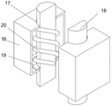
FIG. 4 is a schematic view of a fixing block according to the present invention;
FIG. 5 is a schematic view of a connecting block according to the present invention;
FIG. 6 is a schematic view of the top plate structure of the present invention;
FIG. 7 is a schematic view of the outer column structure of the present invention;
FIG. 8 is a schematic bottom view of the connecting plate of the present invention.
In the figure: 1. a lower support pillar; 2. an upper support column; 3. a main hydraulic press; 4. a column groove; 5. a main rotating groove; 6. a post hole; 7. a main rotating rod; 8. a base plate; 9. plate holes; 10. a bolt; 11. a side block; 12. an inner block; 13. a block hole; 14. a block groove; 15. a sliding groove; 16. a fixed block; 17. moving the hole; 18. moving the rod; 19. an inner plate; 20. a spring; 21. an auxiliary limiting block; 22. a side bar; 23. connecting blocks; 24. connecting grooves; 25. a side groove; 26. a main limiting block; 27. a main rotation hole; 28. a top plate; 29. a fixing hole; 30. a fixing rod; 31. a slider; 32. fixing a column; 33. a limiting groove; 34. an inner tank; 35. an outer bar; 36. an outer block; 37. an outer column; 38. a secondary hydraulic machine; 39. rotating the block; 40. a top hole; 41. an auxiliary rotation hole; 42. an auxiliary rotating groove; 43. an auxiliary rotating rod; 44. a connecting plate; 45. a limiting plate; 46. and a limiting hole.
Detailed Description
The technical solutions in the embodiments of the present invention will be clearly and completely described below with reference to the drawings in the embodiments of the present invention, and it is obvious that the described embodiments are only a part of the embodiments of the present invention, and not all of the embodiments. All other embodiments, which can be obtained by a person skilled in the art without making any creative effort based on the embodiments in the present invention, belong to the protection scope of the present invention.
Referring to fig. 1-8, a column support member for steel structure factory building comprises two lower support columns 1, two lower support columns 1 are provided, the lower support columns 1 are hollow rectangular structures, the top surfaces of the lower support columns 1 are open, the top surfaces of the lower support columns 1 are provided with upper support columns 2, the upper support columns 2 are rectangular structures, a main hydraulic press 3 is fixedly installed inside the lower support columns 1, the main hydraulic press 3 is an existing structure and is not described herein, the top ends of shafts of the hydraulic presses 3 are fixedly installed on the bottom surfaces of the upper support columns 2, the upper support columns 2 are installed on the top surfaces of the lower support columns 1 through the main hydraulic press 3, the top surfaces of the upper support columns 2 are provided with rotating mechanisms, bottom plates 8 are fixedly installed on the bottom surfaces of the lower support columns 1, the bottom plates 8 are rectangular structures, plate holes 9 are formed in four corner positions of the top surfaces of the bottom plates 8, the plate holes 9 are threaded holes, bolts 10 are connected to the internal threads of the plate holes 9, bolt 10 does not need to be repeated here for existing structure, and one side of going up support column 2 is provided with side piece 11, the hollow rectangle structure of side piece 11, and one side of side piece 11 is uncovered, and the inside of side piece 11 is provided with slide mechanism, and one side of side piece 11 is provided with coupling mechanism, goes up one side of support column 2 and is provided with elevating system.
Through setting up bolt 10, when rotating bolt 10 through the staff, when bolt 10 rotated in the inside of diaphragm orifice 9, bolt 10 passed through diaphragm orifice 9 this moment and can down moved, from making bottom plate 8 fixed mounting on the ground, when bottom plate 8 fixed back, support column 1 fixed mounting under bottom plate 8 can drive this moment to make the device be convenient for fix in different places.
Further, in the above scheme, the rotating mechanism includes a column groove 4, the top surface of the upper support column 2 is provided with the column groove 4, the column groove 4 is a rectangular groove, one side inside the column groove 4 is provided with a main rotating groove 5, the main rotating groove 5 is a threaded groove, one side of the upper support column 2 is provided with a column hole 6, the column hole 6 is a circular through hole, a main rotating rod 7 is movably sleeved inside the column hole 6, the main rotating rod 7 is a structure formed by a cylindrical block, the outer circumferential wall surface of the main rotating rod 7 is provided with a threaded groove, one end of the main rotating rod 7 passes through the column hole 6 and extends into the column groove 4, one end of the main rotating rod 7 passes through the column hole 6 and is in threaded connection with the main rotating groove 5, one side of the side block 11 is fixedly provided with a main limiting block 26, the main limiting block 26 is a rectangular structure, the main limiting block 26 is movably clamped with the column groove 4, one side of the main limiting block 26 is provided with a main rotating hole 27, the main hole 27 that rotates is circular through-hole, and main hole 27 and the activity of rotating stick 7 are cup jointed together, and main stopper 26 rotates through main hole 27 and installs in the inside of post groove 4, and side piece 11 rotates through main stopper 26 and installs in one side of upper support post 2.
Through setting up main hydraulic press 3, the staff is when starting main hydraulic press 3, can drive support column 2 and remove when main hydraulic press 3 is at the axle of main hydraulic press 3 of during operation, and support column 2 can drive side block 11 and remove through main rotating rod 7 when last support column 2 when removing, the height through the adjustable factory building support column of main hydraulic press 3 this moment to make the device be convenient for adjust the height of support column.
Further, in the above scheme, the sliding mechanism includes an inner block 12, the inner block 12 is movably clamped inside the side block 11, the inner block 12 is of a rectangular structure, the top surface and the bottom surface of the inner block 12 are both provided with a plurality of block grooves 14, the block grooves 14 are circular grooves, the top surface and the bottom surface of the side block 11 are both provided with a plurality of block holes 13, the block holes 13 are rectangular grooves, a fixed block 16 is fixedly installed inside the block holes 13, the fixed block 16 is of a hollow rectangular structure, the top surface and the bottom surface of the fixed block 16 are both provided with a moving hole 17, the moving hole 17 is a circular through hole, the inside of the fixed block 16 is provided with a moving rod 18, the moving rod 18 is of a cylindrical structure, the moving rod 18 and the moving hole 17 are movably sleeved together, the top end of the moving rod 18 passes through the moving hole 17 located on the top surface of the fixed block 16 and extends to the outside of the fixed block 16, the bottom end of the moving rod 18 passes through the moving hole 17 located on the bottom surface of the fixed block 16 and extends to the outside of the fixed block 16, an inner plate 19 is fixedly mounted on the outer circle wall surface of the moving rod 18, the inner plate 19 is of a circular ring structure, the moving rod 18 is mounted inside the fixed block 16 through the inner plate 19, a spring 20 is fixedly mounted at the top end of the inside of the fixed block 16, the spring 20 is of an existing structure and is not described herein, the bottom end of the spring 20 is fixedly mounted at the top end of the inner plate 19, the moving rod 18 is movably sleeved with the block groove 14, the inner block 12 is fixedly mounted inside the side block 11 through the block groove 14, two sliding grooves 15 are formed in the top surface of the inner block 12, and the sliding grooves 15 are T-shaped grooves.
Through the arrangement of the moving rod 18, after an operator pulls the inner plate 19, the moving rod 18 drives the spring 20 to move through the inner plate 19, the spring 20 is stressed to generate acting force when the spring 20 moves, after the moving rod 18 moves out of the inner part of the block groove 14, the operator can move the inner block 12 out of the inner part of the side block 11, and when the operator loosens the moving rod 18, the acting force generated by the spring 20 drives the moving rod 18 to move through the inner plate 19, so that the moving rod 18 moves back to the original position, and the device is convenient to disassemble and carry.
Further, in the above scheme, the connecting mechanism includes an auxiliary limiting block 21, an auxiliary limiting block 21 is fixedly installed on one side of each of the inner blocks 12, the auxiliary limiting block 21 is of a rectangular structure, side rods 22 are fixedly installed on two sides of each of the auxiliary limiting blocks 21, the side rods 22 are of a cylindrical structure, a connecting block 23 is arranged between the two inner blocks 12, the connecting block 23 is of a rectangular structure, connecting grooves 24 are respectively formed on two sides of each of the connecting blocks 23, the connecting grooves 24 are rectangular grooves, the connecting grooves 24 are in interactive clamping connection with the auxiliary limiting block 21, side grooves 25 are respectively formed on two sides of each of the connecting grooves 24, the side grooves 25 are circular grooves, the side rods 22 are movably sleeved with the side grooves 25, the auxiliary limiting block 21 is rotatably installed inside the connecting grooves 24 through the side rods 22, the connecting block 23 is fixedly installed between the two inner blocks 12 through the connecting grooves 24, and the top surfaces of the inner blocks 12 are provided with a plurality of top plates 28, roof 28 is the rectangle structure, roof 28's bottom surface fixed mounting has two sliding blocks 31, sliding block 31 is T font structure, sliding block 31 and sliding tray 15 activity joint together, roof 28 passes through sliding block 31 fixed mounting at the top surface of inner block 12, fixed orifices 29 has been seted up to roof 28's top surface, fixed orifices 29 is circular through-hole, fixed rod 30 has been cup jointed in the inside activity of fixed orifices 29, fixed rod 30 is cylindrical structure, fixed rod 30 cup joints together with a block groove 14 activity.
Through setting up roof 28, after the staff has driven side piece 11 through vice hydraulic press 38 and has adjusted the angle, the staff is at pulling fixed rod 30 this moment, shift out fixed rod 30 behind the inside of piece groove 14, roof 28 passes through the top surface slip that sliding block 31 can take interior piece 12, after the distance of interior piece 12 is adjusted, the staff is in cup jointing fixed rod 30 and the activity of piece groove 14 together this moment, thereby make roof 28 fixed mounting at the top surface of piece groove 14, prevent that roof 28 from removing, can make the device roof improve the area of contact of side piece 11 after adjusting in the installation too much through roof 28, be convenient for the staff installs the roof.
Further, in the above scheme, the lifting mechanism includes a fixed column 32, the fixed column 32 is fixedly installed on one side of the upper support column 2, the fixed column 32 is of a cylindrical structure, one end of the fixed column 32 is provided with a limit groove 33, the limit groove 33 is a rectangular groove, inner grooves 34 are respectively formed on two sides of the limit groove 33 close to each other, the inner grooves 34 are circular through holes, an outer block 36 is movably clamped inside the limit groove 33, the outer block 36 is of a rectangular structure, outer bars 35 are fixedly installed on two sides of the outer block 36 far away from each other, the outer bars 35 are of a cylindrical structure, the outer bars 35 are movably sleeved with the inner grooves 34, the outer block 36 is rotatably installed inside the limit groove 33 through the outer bars 35, an outer column 37 is fixedly installed on one side of the outer block 36, the outer column 37 is of a hollow cylindrical structure, one end of the outer column 37 is open, an auxiliary hydraulic press 38 is fixedly installed at one end inside the outer column 37, the auxiliary hydraulic press 38 is an existing structure and is not described herein, one end of an axis of the auxiliary hydraulic press 38 is fixedly provided with a rotating block 39, the rotating block 39 is a rectangular structure, the top surface of the rotating block 39 is provided with a top hole 40, the top hole 40 is a rectangular through hole, one side inside the top hole 40 is provided with an auxiliary rotating groove 42, the auxiliary rotating groove 42 is a threaded groove, one side of the rotating block 39 is provided with an auxiliary rotating hole 41, the auxiliary rotating hole 41 is a circular through hole, an auxiliary rotating rod 43 is movably sleeved inside the auxiliary rotating hole 41, the auxiliary rotating rod 43 is a structure formed by cylindrical round blocks, the outer circumferential wall surface of the auxiliary rotating rod 43 is provided with a threaded groove, one end of the auxiliary rotating rod 43 passes through the auxiliary rotating hole 41 and extends into the top hole 40, one end of the auxiliary rotating rod 43 passes through the auxiliary rotating hole 41 and is in threaded connection with the auxiliary rotating groove 42, the bottom surface of the side block 11 is fixedly provided with a connecting plate 44, the connecting plate 44 is a round block-shaped structure, the bottom fixed mounting of connecting plate 44 has limiting plate 45, and limiting plate 45 is the arc structure, and limiting plate 45 and the movable joint of apical pore 40 are in the same place, and spacing hole 46 has been seted up to one side of limiting plate 45, and spacing hole 46 is circular through-hole, and spacing hole 46 cup joints together with vice rotating rod 43 activity, and limiting plate 45 rotates through spacing hole 46 and installs the inside at apical pore 40.
Through setting up vice hydraulic press 38, when vice hydraulic press 38 is at the during operation vice hydraulic press 38 passes through turning block 39 and drives connecting plate 44 and remove, when connecting plate 44 is when removing, connecting plate 44 can drive side piece 11 and upwards remove this moment, and side piece 11 rotates in one side of upper support post 2 through main stopper 26 this moment, when main stopper 26 rotated in the inside of post groove 4, made side piece 11 be convenient for angle regulation.
When using, through setting up vice hydraulic press 38, when vice hydraulic press 38 passes through turning block 39 at during operation vice hydraulic press 38 and drives connecting plate 44 and remove, when connecting plate 44 is when removing, connecting plate 44 can drive side piece 11 and up remove this moment, side piece 11 rotates in one side of upper support post 2 through main stopper 26 this moment, when main stopper 26 rotates in the inside of post groove 4, make side piece 11 be convenient for angle regulation, main stopper 26 can prevent through main rotation hole 27 that main stopper 26 from shifting out the inside of post groove 4, thereby make the device be convenient for adjust the angle on factory building roof.
Through setting up main hydraulic press 3, the staff is when starting main hydraulic press 3, can drive support column 2 and remove when main hydraulic press 3 is at the axle of main hydraulic press 3 of during operation, and support column 2 can drive side block 11 and remove through main rotating rod 7 when last support column 2 when removing, the height through the adjustable factory building support column of main hydraulic press 3 this moment to make the device be convenient for adjust the height of support column.
Through setting up bolt 10, when rotating bolt 10 through the staff, when bolt 10 rotated in the inside of diaphragm orifice 9, bolt 10 passed through diaphragm orifice 9 this moment and can down moved, from making 8 fixed mounting of bottom plate on the ground, when 8 fixed backs of bottom plate, 8 fixed mounting of support column 1 under can driving of bottom plate this moment in the bottom surface to make the device be convenient for fix in different places.
Through setting up roof 28, after the staff has adjusted the angle through vice hydraulic press 38 drive side piece 11, the staff is at pulling fixed rod 30 this moment, shift out fixed rod 30 behind the inside of piece groove 14, roof 28 passes through the top surface that sliding block 31 can take in block 12 and slides, after the distance of interior block 12 was adjusted, the staff is in cup jointing fixed rod 30 and the activity of piece groove 14 together this moment, thereby make roof 28 fixed mounting at the top surface of piece groove 14, prevent that roof 28 from removing, can make the device roof improve the area of contact of side piece 11 after adjusting in the installation too much through roof 28, be convenient for the staff installs the roof.
Through the arrangement of the moving rod 18, after an operator pulls the inner plate 19, the moving rod 18 drives the spring 20 to move through the inner plate 19, the spring 20 is stressed to generate acting force when the spring 20 moves, after the moving rod 18 moves out of the inner part of the block groove 14, the operator can move the inner block 12 out of the inner part of the side block 11, and when the operator loosens the moving rod 18, the acting force generated by the spring 20 drives the moving rod 18 to move through the inner plate 19, so that the moving rod 18 moves back to the original position, and the device is convenient to transport after being disassembled.
Although embodiments of the present invention have been shown and described, it will be appreciated by those skilled in the art that various changes, modifications, substitutions and alterations can be made in these embodiments without departing from the principles and spirit of the invention, the scope of which is defined in the appended claims and their equivalents.
Claims (6)
1. The utility model provides a steel construction is column shoring component for factory building construction, includes lower support column (1), its characterized in that: the utility model discloses a hydraulic press, including bottom suspension dagger (1), the top surface of bottom suspension dagger (1) is provided with support column (2), the inside fixed mounting of bottom suspension dagger (1) has main hydraulic press (3), the top fixed mounting of main hydraulic press (3) axle is in the bottom surface of upper support column (2), upper support column (2) is installed at the top surface of bottom suspension dagger (1) through main hydraulic press (3), the top surface of upper support column (2) is provided with slewing mechanism, the bottom surface fixed mounting of bottom suspension dagger (1) has bottom plate (8), four turning positions of bottom plate (8) top surface have all been seted up pore (9), the inside threaded connection of pore (9) has bolt (10), one side of upper support column (2) is provided with side piece (11), the inside of side piece (11) is provided with slide mechanism, one side of side piece (11) is provided with coupling mechanism, one side of upper support column (2) is provided with elevating system, the lifting mechanism comprises a fixing column (32), the fixing column (32) is fixedly installed on one side of the upper supporting column (2), a limiting groove (33) is formed in one end of the fixing column (32), inner grooves (34) are formed in two sides, close to each other, in the limiting groove (33), outer blocks (36) are movably clamped in the limiting groove (33), outer rods (35) are fixedly installed on two sides, far away from each other, of the outer blocks (36), the outer rods (35) are movably sleeved with the inner grooves (34), the outer blocks (36) are rotatably installed in the limiting groove (33) through the outer rods (35), outer columns (37) are fixedly installed on one sides of the outer blocks (36), an auxiliary hydraulic press (38) is fixedly installed at one end of the inner portion of each outer column (37), a rotating block (39) is fixedly installed at one end of a shaft of the auxiliary hydraulic press (38), top holes (40) are formed in the top surface of each rotating block (39), an auxiliary rotating groove (42) is formed in one side of the inner portion of each top hole (40), vice rotation hole (41) have been seted up to one side of turning block (39), vice rotation rod (43) have been cup jointed in the inside activity of vice rotation hole (41), the thread groove has been seted up to the excircle wall of vice rotation rod (43), the inside that vice rotation hole (41) extended to apical pore (40) is passed to the one end of vice rotation rod (43), vice rotation hole (41) is passed to the one end of vice rotation rod (43) and vice rotation groove (42) threaded connection is in the same place, the bottom surface fixed mounting of side piece (11) has connecting plate (44), the bottom fixed mounting of connecting plate (44) has limiting plate (45), limiting plate (45) and apical pore (40) activity joint are in the same place, spacing hole (46) have been seted up to one side of limiting plate (45), spacing hole (46) and vice rotation rod (43) activity cup joint are in the same place, limiting plate (45) rotate through limiting hole (46) and install the inside at apical pore (40).
2. The column support member for steel structure factory building construction according to claim 1, characterized in that: the rotating mechanism comprises a column groove (4), a column groove (4) is formed in the top surface of the upper supporting column (2), a main rotating groove (5) is formed in one side of the interior of the column groove (4), a column hole (6) is formed in one side of the upper supporting column (2), a main rotating rod (7) is movably sleeved in the column hole (6), a thread groove is formed in the outer circle wall surface of the main rotating rod (7), one end of the main rotating rod (7) penetrates through the column hole (6) and extends into the column groove (4), one end of the main rotating rod (7) penetrates through the column hole (6) and is in threaded connection with the main rotating groove (5), a main limiting block (26) is fixedly installed on one side of the side block (11), the main limiting block (26) is movably clamped with the column groove (4), a main rotating hole (27) is formed in one side of the main limiting block (26), and the main rotating hole (27) is movably sleeved with the main rotating rod (7), the main limiting block (26) is rotatably installed inside the column groove (4) through the main rotating hole (27), and the side block (11) is rotatably installed on one side of the upper supporting column (2) through the main limiting block (26).
3. The column support member for steel structure factory building construction according to claim 1, characterized in that: slide mechanism includes inner block (12), the inside movable joint of side piece (11) has inner block (12), a plurality of piece groove (14) have all been seted up with the bottom surface to the top surface of inner block (12), a plurality of piece hole (13) have all been seted up with the bottom surface to the top surface of side piece (11), the inside fixed mounting of piece hole (13) has fixed block (16), removal hole (17) have all been seted up with the bottom surface to the top surface of fixed block (16), the inside of fixed block (16) is provided with removes stick (18), remove stick (18) and remove hole (17) activity cup joint together, the top of removing stick (18) is passed removal hole (17) that are located fixed block (16) top surface and is extended to the outside of fixed block (16).
4. The column support component for the construction of the steel structure factory building according to claim 3, wherein: the bottom of removal stick (18) passes removal hole (17) that are located fixed block (16) bottom surface and extends to the outside of fixed block (16), the excircle wall fixed mounting who removes stick (18) has inner panel (19), remove stick (18) and install the inside at fixed block (16) through inner panel (19), the inside top fixed mounting of fixed block (16) has spring (20), the bottom fixed mounting of spring (20) is on the top of inner panel (19), remove stick (18) and block groove (14) activity cup joint together, inner block (12) are through the inside of block groove (14) fixed mounting in side piece (11), two sliding tray (15) have been seted up to the top surface of inner block (12), sliding tray (15) are the T shape groove.
5. The column support component for the construction of the steel structure factory building according to claim 3, wherein: coupling mechanism includes vice stopper (21), one side fixed mounting of interior piece (12) has vice stopper (21), the equal fixed mounting in both sides that vice stopper (21) kept away from each other has side stick (22), be provided with connecting block (23) between two interior pieces (12), connecting groove (24) have all been seted up to the both sides that connecting block (23) kept away from each other, connecting groove (24) are in the same place with vice stopper (21) interactive joint, side channel (25) have all been seted up to the inside both sides that are close to each other of connecting groove (24), side stick (22) cup joint together with side channel (25) activity.
6. The column support component for the construction of the steel structure factory building according to claim 5, wherein: vice stopper (21) are rotated through side stick (22) and are installed in the inside of spread groove (24), connecting block (23) are through spread groove (24) fixed mounting between two inner blocks (12), the top surface of inner block (12) is provided with a plurality of roof (28), the bottom surface fixed mounting of roof (28) has two sliding blocks (31), sliding block (31) are T font structure, sliding block (31) and sliding tray (15) activity joint are in the same place, roof (28) are through the top surface of sliding block (31) fixed mounting in inner block (12), fixed orifices (29) have been seted up to the top surface of roof (28), fixed stick (30) have been cup jointed in the inside activity of fixed orifices (29), fixed stick (30) and block groove (14) activity are cup jointed together.
Priority Applications (1)
| Application Number | Priority Date | Filing Date | Title |
|---|---|---|---|
| CN202110153829.5A CN113006374B (en) | 2021-02-04 | 2021-02-04 | Column support component for construction of steel structure factory building |
Applications Claiming Priority (1)
| Application Number | Priority Date | Filing Date | Title |
|---|---|---|---|
| CN202110153829.5A CN113006374B (en) | 2021-02-04 | 2021-02-04 | Column support component for construction of steel structure factory building |
Publications (2)
| Publication Number | Publication Date |
|---|---|
| CN113006374A CN113006374A (en) | 2021-06-22 |
| CN113006374B true CN113006374B (en) | 2022-06-28 |
Family
ID=76383797
Family Applications (1)
| Application Number | Title | Priority Date | Filing Date |
|---|---|---|---|
| CN202110153829.5A Active CN113006374B (en) | 2021-02-04 | 2021-02-04 | Column support component for construction of steel structure factory building |
Country Status (1)
| Country | Link |
|---|---|
| CN (1) | CN113006374B (en) |
Citations (5)
| Publication number | Priority date | Publication date | Assignee | Title |
|---|---|---|---|---|
| AU6377590A (en) * | 1989-11-13 | 1991-05-16 | Lewis Ronald Harding | Force transmitting apparatus |
| SU1733585A1 (en) * | 1989-05-04 | 1992-05-15 | Центральное морское конструкторское бюро "Алмаз" | Collapsible spatial structure |
| CN111197349A (en) * | 2020-01-08 | 2020-05-26 | 亚鹰建筑科技集团有限公司 | Steel structure assembly type building convenient to install and assembly method |
| CN210658712U (en) * | 2019-07-30 | 2020-06-02 | 上海互集建筑科技有限公司 | Steel construction coupling assembling with waterproof function |
| CN210658691U (en) * | 2019-08-15 | 2020-06-02 | 河南省腾程建筑工程有限公司 | Support-free assembled steel structure |
Family Cites Families (9)
| Publication number | Priority date | Publication date | Assignee | Title |
|---|---|---|---|---|
| DE4321401C2 (en) * | 1992-11-14 | 1997-04-10 | Klaus Bau Gmbh | Device for changing the height distance of a roof structure from the top floor |
| US8869465B2 (en) * | 2008-01-15 | 2014-10-28 | Design And Value Management Services Pty Ltd. | Process for providing emergency housing for a plurality of displaced people |
| US9874036B2 (en) * | 2015-05-08 | 2018-01-23 | Cannon Design Products Group, Llc | Prefabricated, deconstructable, multistory building construction |
| CN207582681U (en) * | 2017-10-25 | 2018-07-06 | 阳地钢(上海)装配式建筑股份有限公司 | The assembly type crossbeam of modularization steel structure system |
| CN209277293U (en) * | 2018-12-29 | 2019-08-20 | 南京雨盛建筑设计咨询有限公司 | A kind of assembled architecture house roof bracket |
| CN110424609A (en) * | 2019-08-14 | 2019-11-08 | 华南理工大学建筑设计研究院有限公司 | The photovoltaic roof of herringbone adjustable angle |
| CN211114101U (en) * | 2019-09-17 | 2020-07-28 | 重庆及能建筑安装有限公司 | But quick assembly disassembly's steel construction board house |
| CN212427534U (en) * | 2020-04-25 | 2021-01-29 | 山东华泰钢结构工程有限公司 | Adjustable supporting framework of steel structure factory building |
| CN111910761A (en) * | 2020-07-30 | 2020-11-10 | 新十建设集团有限公司 | Column support component for steel structure factory building construction |
-
2021
- 2021-02-04 CN CN202110153829.5A patent/CN113006374B/en active Active
Patent Citations (5)
| Publication number | Priority date | Publication date | Assignee | Title |
|---|---|---|---|---|
| SU1733585A1 (en) * | 1989-05-04 | 1992-05-15 | Центральное морское конструкторское бюро "Алмаз" | Collapsible spatial structure |
| AU6377590A (en) * | 1989-11-13 | 1991-05-16 | Lewis Ronald Harding | Force transmitting apparatus |
| CN210658712U (en) * | 2019-07-30 | 2020-06-02 | 上海互集建筑科技有限公司 | Steel construction coupling assembling with waterproof function |
| CN210658691U (en) * | 2019-08-15 | 2020-06-02 | 河南省腾程建筑工程有限公司 | Support-free assembled steel structure |
| CN111197349A (en) * | 2020-01-08 | 2020-05-26 | 亚鹰建筑科技集团有限公司 | Steel structure assembly type building convenient to install and assembly method |
Also Published As
| Publication number | Publication date |
|---|---|
| CN113006374A (en) | 2021-06-22 |
Similar Documents
| Publication | Publication Date | Title |
|---|---|---|
| US3815858A (en) | Roll out formwork support | |
| CN210687447U (en) | Municipal administration is fixed bolster for heating power pipeline | |
| CN208669004U (en) | Room is built with adjustable late poured band support device | |
| CN111364757A (en) | Supporting structure of steel bar truss floor bearing plate | |
| CN113006374B (en) | Column support component for construction of steel structure factory building | |
| CN212582721U (en) | Bearing platform of tower crane for vertical tower of top plate of foundation garage | |
| CN105507625A (en) | Spliced container type multifunctional mobile workshop | |
| CN213114883U (en) | Frock for concrete placement based on drainage ditch of falling trapezoidal form | |
| CN211772862U (en) | Adjustable support frame for cast-in-place beam template | |
| CN218375395U (en) | Adjusting device of factory building steel column elevation | |
| CN211074262U (en) | Processing device of anti-leakage structure of bottom die of floor support plate of non-dismantling steel bar truss | |
| CN215313784U (en) | Angle-controllable steel slag raw slag screening mesh screen | |
| CN220394276U (en) | Pile foundation convenient to installation steel landing stage | |
| CN211387689U (en) | Steel structure plate cutting device | |
| CN218757495U (en) | Slope-shaped independent foundation formwork support and slope forming control tool | |
| CN219826232U (en) | Assembly type steel structure auxiliary construction equipment | |
| CN219158173U (en) | Steel structure beam | |
| CN216109714U (en) | Simple beam bottom supporting device with cast-in-place structure | |
| CN216339056U (en) | Precast beam hogging moment stretch-draw jack trolley | |
| CN220035444U (en) | Foundation pit supporting device for constructional engineering | |
| CN216270881U (en) | T-shaped beam transportation protection device for railway construction | |
| CN218176703U (en) | Adjusting bracket | |
| CN212176556U (en) | Supporting structure of steel bar truss floor bearing plate | |
| CN217897299U (en) | Quick leveling device for integral wall formwork | |
| CN218933804U (en) | Scaffold mounting platform reinforcing apparatus |
Legal Events
| Date | Code | Title | Description |
|---|---|---|---|
| PB01 | Publication | ||
| PB01 | Publication | ||
| SE01 | Entry into force of request for substantive examination | ||
| SE01 | Entry into force of request for substantive examination | ||
| CB02 | Change of applicant information | ||
| CB02 | Change of applicant information |
Address after: No. 1958, Chuangye street, Changchun automobile economic and Technological Development Zone, Changchun City, Jilin Province, 130011 Applicant after: The Ninth Design and Research Institute of Machinery Industry Co., Ltd Address before: No. 1958, Chuangye street, Changchun automobile economic and Technological Development Zone, Changchun City, Jilin Province, 130011 Applicant before: The Ninth Design and Research Institute of Machinery Industry Co., Ltd |
|
| GR01 | Patent grant | ||
| GR01 | Patent grant |