CN112974423A - Water-gas interaction pulse cleaning device with vacuum function and method - Google Patents
Water-gas interaction pulse cleaning device with vacuum function and method Download PDFInfo
- Publication number
- CN112974423A CN112974423A CN202110197306.0A CN202110197306A CN112974423A CN 112974423 A CN112974423 A CN 112974423A CN 202110197306 A CN202110197306 A CN 202110197306A CN 112974423 A CN112974423 A CN 112974423A
- Authority
- CN
- China
- Prior art keywords
- water
- valve
- gas
- supplementing
- vacuum
- Prior art date
- Legal status (The legal status is an assumption and is not a legal conclusion. Google has not performed a legal analysis and makes no representation as to the accuracy of the status listed.)
- Pending
Links
Images


Classifications
-
- B—PERFORMING OPERATIONS; TRANSPORTING
- B08—CLEANING
- B08B—CLEANING IN GENERAL; PREVENTION OF FOULING IN GENERAL
- B08B9/00—Cleaning hollow articles by methods or apparatus specially adapted thereto
- B08B9/02—Cleaning pipes or tubes or systems of pipes or tubes
- B08B9/027—Cleaning the internal surfaces; Removal of blockages
- B08B9/032—Cleaning the internal surfaces; Removal of blockages by the mechanical action of a moving fluid, e.g. by flushing
- B08B9/0321—Cleaning the internal surfaces; Removal of blockages by the mechanical action of a moving fluid, e.g. by flushing using pressurised, pulsating or purging fluid
- B08B9/0328—Cleaning the internal surfaces; Removal of blockages by the mechanical action of a moving fluid, e.g. by flushing using pressurised, pulsating or purging fluid by purging the pipe with a gas or a mixture of gas and liquid
-
- B—PERFORMING OPERATIONS; TRANSPORTING
- B08—CLEANING
- B08B—CLEANING IN GENERAL; PREVENTION OF FOULING IN GENERAL
- B08B13/00—Accessories or details of general applicability for machines or apparatus for cleaning
-
- B—PERFORMING OPERATIONS; TRANSPORTING
- B08—CLEANING
- B08B—CLEANING IN GENERAL; PREVENTION OF FOULING IN GENERAL
- B08B9/00—Cleaning hollow articles by methods or apparatus specially adapted thereto
- B08B9/02—Cleaning pipes or tubes or systems of pipes or tubes
- B08B9/027—Cleaning the internal surfaces; Removal of blockages
- B08B9/032—Cleaning the internal surfaces; Removal of blockages by the mechanical action of a moving fluid, e.g. by flushing
- B08B9/0321—Cleaning the internal surfaces; Removal of blockages by the mechanical action of a moving fluid, e.g. by flushing using pressurised, pulsating or purging fluid
- B08B9/0325—Control mechanisms therefor
-
- B—PERFORMING OPERATIONS; TRANSPORTING
- B08—CLEANING
- B08B—CLEANING IN GENERAL; PREVENTION OF FOULING IN GENERAL
- B08B9/00—Cleaning hollow articles by methods or apparatus specially adapted thereto
- B08B9/02—Cleaning pipes or tubes or systems of pipes or tubes
- B08B9/027—Cleaning the internal surfaces; Removal of blockages
- B08B9/032—Cleaning the internal surfaces; Removal of blockages by the mechanical action of a moving fluid, e.g. by flushing
- B08B9/0321—Cleaning the internal surfaces; Removal of blockages by the mechanical action of a moving fluid, e.g. by flushing using pressurised, pulsating or purging fluid
- B08B9/0326—Using pulsations
-
- B—PERFORMING OPERATIONS; TRANSPORTING
- B08—CLEANING
- B08B—CLEANING IN GENERAL; PREVENTION OF FOULING IN GENERAL
- B08B9/00—Cleaning hollow articles by methods or apparatus specially adapted thereto
- B08B9/02—Cleaning pipes or tubes or systems of pipes or tubes
- B08B9/027—Cleaning the internal surfaces; Removal of blockages
- B08B9/032—Cleaning the internal surfaces; Removal of blockages by the mechanical action of a moving fluid, e.g. by flushing
- B08B9/035—Cleaning the internal surfaces; Removal of blockages by the mechanical action of a moving fluid, e.g. by flushing by suction
-
- F—MECHANICAL ENGINEERING; LIGHTING; HEATING; WEAPONS; BLASTING
- F24—HEATING; RANGES; VENTILATING
- F24H—FLUID HEATERS, e.g. WATER OR AIR HEATERS, HAVING HEAT-GENERATING MEANS, e.g. HEAT PUMPS, IN GENERAL
- F24H9/00—Details
- F24H9/12—Arrangements for connecting heaters to circulation pipes
- F24H9/13—Arrangements for connecting heaters to circulation pipes for water heaters
-
- F—MECHANICAL ENGINEERING; LIGHTING; HEATING; WEAPONS; BLASTING
- F24—HEATING; RANGES; VENTILATING
- F24H—FLUID HEATERS, e.g. WATER OR AIR HEATERS, HAVING HEAT-GENERATING MEANS, e.g. HEAT PUMPS, IN GENERAL
- F24H9/00—Details
- F24H9/18—Arrangement or mounting of grates or heating means
- F24H9/1809—Arrangement or mounting of grates or heating means for water heaters
-
- F—MECHANICAL ENGINEERING; LIGHTING; HEATING; WEAPONS; BLASTING
- F24—HEATING; RANGES; VENTILATING
- F24H—FLUID HEATERS, e.g. WATER OR AIR HEATERS, HAVING HEAT-GENERATING MEANS, e.g. HEAT PUMPS, IN GENERAL
- F24H9/00—Details
- F24H9/20—Arrangement or mounting of control or safety devices
- F24H9/2007—Arrangement or mounting of control or safety devices for water heaters
Abstract
The water-gas interaction pulse cleaning device with the vacuum function comprises a water circulation system, a water supplementing device, a gas supplementing device and a PLC control system, wherein the water supplementing device is connected with a water tank of the water circulation system, the gas supplementing device is connected with a water circulation pipeline of the water circulation system, the PLC control system controls the water supplementing device to supplement water to the water circulation system, the gas supplementing device supplements gas to the water circulation system, and a water-gas mixture is formed to enter a bar water branch for cleaning and descaling. The invention overcomes the problems of incomplete cleaning of the water branch of the bar of the internal water cooling generator, insufficient blockage removal capacity and easy oxidation of the inner wall of the bar, and has the characteristics of simple structure, vacuum extraction of water and gas impurities, prevention of oxidation of the inner wall of the bar, adjustable water and gas pulse ratio, energy conservation, thorough cleaning and simple and convenient operation.
Description
Technical Field
The invention belongs to the technical field of pipeline cleaning, and relates to a water-gas interaction pulse cleaning device with a vacuum function and a method.
Background
At present, in the long-time operation process of a water branch of a coil bar of a water-cooled generator, due to corrosion, oxidation and impurities in water, the corners and the bent parts of a cooling element can generate scale deposits, and the sectional area of a hollow copper wire is small (usually 11mm x 2 mm), so that a pipeline is easily blocked, the generator is locally overheated, and the long-time operation can cause insulation failure and even generator faults. If the generator fails in the period of flood season, huge economic loss is brought.
The line bar water branch is difficult to clean by the traditional method because of the narrow water path. In a thermal power generating set, a mode of manually switching cooling water paths is generally adopted to prevent blockage; in hydroelectric power generation units, pressurized flushing with pure water is generally used. Other industries also have devices for cleaning waterways by using a water-gas pulse mode, but the devices do not have the functions of self-circulation and direction switching, and have the problems of large water consumption and insufficient dredging capability. The water-gas pulse ratio adjustable function is not provided, and the flexibility of matching and cleaning different pipelines is lacked. In addition, other water-air pulse devices adopt a mixing mode of common water and compressed air, impurities in the water and oxygen in the air have oxidation effects on the inner wall of the generator coil bar, and the oxides are unfavorable to a pipeline.
Disclosure of Invention
The technical problem to be solved by the invention is to provide a water-gas interaction pulse cleaning device with a vacuum function and a method, the structure is simple, the water replenishing device is connected with a water tank of a water circulation system and is connected with a water circulation pipeline of the water circulation system, a PLC control system controls the water replenishing device to replenish water to the water circulation system, the water replenishing device replenishes air to the water circulation system, a formed water-gas mixture enters a water branch of a winding bar to be cleaned and descaled, water-gas sundries are extracted in vacuum, the oxidation of the inner wall of the winding bar is avoided, the water-gas pulse ratio is adjustable, the energy.
In order to solve the technical problems, the technical scheme adopted by the invention is as follows: a water-gas interaction pulse cleaning device with a vacuum function comprises a water circulation system, a water supplementing device, a gas supplementing device and a PLC control system; the water replenishing device is connected with a water tank of the water circulating system, and the air replenishing device is connected with a water circulating pipeline of the water circulating system; a centrifugal pump, a water circulation electromagnetic valve, an overspeed protection valve and an overpressure protection valve in the water circulation system, and an air supply electromagnetic valve of an air supply device are connected with the PLC control system.
The water circulation system comprises a water tank positioned in a water circulation pipeline, a centrifugal pump, a water circulation electromagnetic valve, an overspeed protection valve, an overpressure protection valve and a one-way valve, wherein the centrifugal pump, the water circulation electromagnetic valve, the overspeed protection valve, the overpressure protection valve and the one-way valve are sequentially connected with the water circulation pipeline from the water outlet end of the water tank.
And a heating rod, a three-section type floating ball switch and a temperature control device which are connected with the PLC control system are arranged in the water tank.
The water supplementing device comprises a water supplementing pump and a water supplementing electromagnetic valve which are sequentially connected with a water supplementing pipeline.
The air supplementing device comprises an air supplementing pipeline connected with an air bottle, a pressure reducing valve, a manual control valve and an air supplementing electromagnetic valve which are sequentially connected with the air supplementing pipeline, and an inflation valve is positioned between the pressure reducing valve and the manual control valve and connected with the air supplementing pipeline.
The vacuum device is a vacuum pumping pump, and the vacuum pumping pump and the vacuum electromagnetic valve are respectively connected with the water circulation pipeline.
An equipment box is arranged on the movable chassis, the water supplementing device and the air supplementing device are located in the equipment box, the water box is located on one side of the equipment box and connected with the movable chassis, and an operation panel of the PLC control system is located outside the equipment box and connected with the equipment box.
A drawer is arranged on one side of the equipment box and is positioned on the lower part of an operation panel of the PLC control system; the side that is located the equipment box sets up the opening and closing door, sets up the louvre on the opening and closing door.
And the water inlet end of the water supplementing device and the air inflation end of the air supplementing device are led out of the equipment box.
The cleaning method of the water-gas interaction pulse cleaning device with the vacuum function comprises the following steps:
s1, mounting, and connecting the water inlet and the water outlet of the bar water branch with a water circulation pipeline to form a water circulation loop;
s2, injecting water, wherein one end of a water supplementing pipeline is communicated with a pure water source, and a PLC control system controls a water supplementing pump and a water supplementing electromagnetic valve to be started to pump pure water into a water tank; stopping water injection when the water level reaches the upper line of a three-section type floating ball switch in the water tank, and closing a water replenishing pump and a water replenishing electromagnetic valve;
s3, inflating, closing the manual control valve, opening an inflation valve connected with an air source, introducing nitrogen into the air supply pipeline along the pressure reducing valve into the air bottle, closing the inflation valve to stop inflating when the pressure value in the air bottle reaches a set value, and opening the manual control valve;
s4, heating, wherein the PLC control system controls the circuit of the heating rod to be closed, and heating is stopped when the temperature reaches a set value;
s5, cleaning, wherein the PLC control system controls the centrifugal pump, the water circulation solenoid valve and the air supply solenoid valve to be opened in sequence;
hot water in the water tank flows through the centrifugal pump, the water circulation electromagnetic valve, the overspeed protection valve, the overvoltage protection valve, the one-way valve and the coil bar water branch in sequence along the water circulation pipeline and then enters the water tank again;
meanwhile, nitrogen of the gas cylinder flows through the pressure reducing valve, the manual control valve and the air supplementing electromagnetic valve along the air supplementing pipeline in sequence to enter the water circulation pipeline, and enters the coil rod water branch together with hot water for descaling and cleaning; at the moment, the water-gas mixture is in a high-temperature high-pressure and high-flow-rate state, impacts the blockage in the water branch of the coil bar and discharges dirt;
and S6, performing vacuum impurity extraction, closing the vacuum electromagnetic valve, starting the vacuum device, extracting water vapor in the wire rod water branch, and simultaneously quickly discharging the rest impurities in the wire rod water branch.
A water-gas interaction pulse cleaning device with a vacuum function comprises a water circulation system, a water supplementing device, a gas supplementing device and a PLC control system; the water replenishing device is connected with a water tank of the water circulating system, and the air replenishing device is connected with a water circulating pipeline of the water circulating system; a centrifugal pump, a water circulation electromagnetic valve, an overspeed protection valve and an overpressure protection valve in the water circulation system, and an air supply electromagnetic valve of an air supply device are connected with the PLC control system. Simple structure is connected through moisturizing device and water circulating system's water tank, and the air supplement unit is connected with water circulating system's water circulating pipe, controls the moisturizing device through PLC control system and to water circulating system moisturizing, and the air supplement unit forms aqueous vapor mixture and gets into line stick water branch road and washs the scale removal, and vacuum extraction aqueous vapor debris avoids line stick inner wall oxidation, and aqueous vapor pulse ratio is adjustable, and is energy-conserving, washs thoroughly, and easy operation is convenient.
In a preferred scheme, the water circulation system comprises a water tank positioned in a water circulation pipeline, a centrifugal pump, a water circulation electromagnetic valve, an overspeed protection valve, an overpressure protection valve and a one-way valve, wherein the centrifugal pump, the water circulation electromagnetic valve, the overspeed protection valve and the overpressure protection valve are sequentially connected with the water circulation pipeline from the water outlet end of the water tank. Simple structure, during the use, the hydrologic cycle pipeline is used for the aqueous vapor circulation, and the water tank is used for the water storage, and the aqueous vapor circulation in the centrifugal pump drive hydrologic cycle pipeline, hydrologic cycle solenoid valve are used for cutting off and break through the hydrologic cycle pipeline.
In a preferable scheme, a heating rod, a three-section type floating ball switch and a temperature control device which are connected with a PLC control system are arranged in the water tank. Simple structure, when adopting hot water washing scale removal, the heating rod heats the water in the water tank, and temperature control device is used for monitoring the temperature, stops heating when the temperature reaches the setting value, and when the temperature was less than the setting value, the circuit of heating rod was closed, heats the water in the water tank.
In a preferred scheme, the water supplementing device comprises a water supplementing pump and a water supplementing electromagnetic valve which are sequentially connected with a water supplementing pipeline. Simple structure, during the use, the moisturizing pipeline is connected with the pure water source, and the moisturizing pump extracts the pure water and pours into the water tank along moisturizing pipeline, moisturizing pump and moisturizing solenoid valve in.
In a preferred scheme, the air supplementing device comprises an air supplementing pipeline connected with an air bottle, a pressure reducing valve, a manual control valve and an air supplementing electromagnetic valve which are sequentially connected with the air supplementing pipeline, and the air charging valve is positioned between the pressure reducing valve and the manual control valve and connected with the air supplementing pipeline. When the gas filling valve is used, after the gas in the gas cylinder is used up, the manual control valve is closed, the gas filling valve is opened to enable the gas source to be communicated with the gas cylinder, the gas enters the gas cylinder through the pressure reducing valve along the gas filling pipeline, and the gas filling valve is closed; when the cleaning and descaling device is used for cleaning and descaling, gas in the gas cylinder enters the water circulation pipeline along the gas supplementing pipeline, the pressure reducing valve, the manual control valve and the gas supplementing electromagnetic valve to form a water-gas mixture.
In a preferred scheme, the vacuum device is a vacuum pumping pump, and the vacuum pumping pump and the vacuum solenoid valve are respectively connected with the water circulation pipeline. Simple structure, during the use, line stick water branch road is located and is connected with the hydrologic cycle pipe between vacuum apparatus and the vacuum solenoid valve, and after line stick water branch road washs, the vacuum solenoid valve was closed, and vacuum apparatus starts, takes out the aqueous vapor in line stick water branch road, and the other debris in line stick water branch road are discharged fast simultaneously.
In the preferred scheme, an equipment box is arranged on the movable chassis, the water supplementing device and the air supplementing device are located in the equipment box, the water box is located on one side of the equipment box and connected with the movable chassis, and an operation panel of the PLC control system is located outside the equipment box and connected with the equipment box. Simple structure, during the use, water circulating system, equipment box are located and remove the chassis, and moisturizing device, air supplement unit are located the equipment box, and PLC control system's operating panel is located the equipment box outside rather than being connected, compact structure, and occupation space is little, the transportation of being convenient for.
In a preferred scheme, a drawer is arranged on one side of the equipment box and is positioned at the lower part of an operation panel of the PLC control system; the side that is located the equipment box sets up the opening and closing door, sets up the louvre on the opening and closing door. The drawer is simple in structure, when the drawer is used, the drawer positioned on one side of the equipment box is used for storing tools, so that the tools can be taken and used quickly in the using process, and the whole space is saved; the opening and closing door positioned on the side surface of the equipment box is opened during maintenance, so that the state of internal equipment can be observed conveniently; the heat dissipation holes positioned on the opening and closing door discharge heat dissipated by equipment in the equipment box in the working process of the equipment.
In a preferable scheme, the water inlet end of the water supplementing device and the air charging end of the air supplementing device are led out of the equipment box. Simple structure, during the use, the end of intaking of moisturizing device, the end of aerifing of air supplement unit draw forth outside the equipment box, at water injection, aerify the in-process, need not to open the equipment box, easy operation is convenient.
In a preferred embodiment, the cleaning method of the water-air interactive pulse cleaning device with the vacuum function comprises the following steps:
s1, mounting, and connecting the water inlet and the water outlet of the bar water branch with a water circulation pipeline to form a water circulation loop;
s2, injecting water, wherein one end of a water supplementing pipeline is communicated with a pure water source, and a PLC control system controls a water supplementing pump and a water supplementing electromagnetic valve to be started to pump pure water into a water tank; stopping water injection when the water level reaches the upper line of a three-section type floating ball switch in the water tank, and closing a water replenishing pump and a water replenishing electromagnetic valve;
s3, inflating, closing the manual control valve, opening an inflation valve connected with an air source, introducing nitrogen into the air supply pipeline along the pressure reducing valve into the air bottle, closing the inflation valve to stop inflating when the pressure value in the air bottle reaches a set value, and opening the manual control valve;
s4, heating, wherein the PLC control system controls the circuit of the heating rod to be closed, and heating is stopped when the temperature reaches a set value;
s5, cleaning, wherein the PLC control system controls the centrifugal pump, the water circulation solenoid valve and the air supply solenoid valve to be opened in sequence;
hot water in the water tank flows through the centrifugal pump, the water circulation electromagnetic valve, the overspeed protection valve, the overvoltage protection valve, the one-way valve and the coil bar water branch in sequence along the water circulation pipeline and then enters the water tank again;
meanwhile, nitrogen of the gas cylinder flows through the pressure reducing valve, the manual control valve and the air supplementing electromagnetic valve along the air supplementing pipeline in sequence to enter the water circulation pipeline, and enters the coil rod water branch together with hot water for descaling and cleaning; at the moment, the water-gas mixture is in a high-temperature high-pressure and high-flow-rate state, impacts the blockage in the water branch of the coil bar and discharges dirt;
and S6, performing vacuum impurity extraction, closing the vacuum electromagnetic valve, starting the vacuum device, extracting water vapor in the wire rod water branch, and simultaneously quickly discharging the rest impurities in the wire rod water branch. The method is simple and convenient to operate, high-temperature, high-pressure and high-flow-rate water vapor is adopted to form a loop to enter the wire rod water branch to impact a blockage, the wire rod water branch is conducted, dirt is cleaned, the blockage removing effect is good, the efficiency is high, and the cleaning is thorough.
The water-gas interaction pulse cleaning device with the vacuum function comprises a water circulation system, a water supplementing device, a gas supplementing device and a PLC control system, wherein the water supplementing device is connected with a water tank of the water circulation system, the gas supplementing device is connected with a water circulation pipeline of the water circulation system, the PLC control system controls the water supplementing device to supplement water to the water circulation system, the gas supplementing device supplements gas to the water circulation system, and a water-gas mixture is formed to enter a bar water branch for cleaning and descaling. The invention overcomes the problems of incomplete cleaning of the water branch of the bar of the internal water cooling generator, insufficient blockage removal capacity and easy oxidation of the inner wall of the bar, and has the characteristics of simple structure, vacuum extraction of water and gas impurities, prevention of oxidation of the inner wall of the bar, adjustable water and gas pulse ratio, energy conservation, thorough cleaning and simple and convenient operation.
Drawings
The invention is further illustrated by the following examples in conjunction with the accompanying drawings:
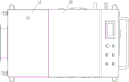
FIG. 1 is a schematic structural diagram of the present invention.
Fig. 2 is a schematic structural view of the connection between the water tank and the movable chassis.
Fig. 3 is a front view of fig. 2.
Fig. 4 is a schematic top view of fig. 3.
In the figure: the water circulation system 1, a water circulation pipeline 11, a water tank 12, a centrifugal pump 13, a water circulation electromagnetic valve 14, an overspeed protection valve 15, an overpressure protection valve 16, a one-way valve 17, a water supplementing device 2, a water supplementing pipeline 21, a water supplementing pump 22, a water supplementing electromagnetic valve 23, a gas supplementing device 3, a gas cylinder 31, a gas supplementing pipeline 32, a pressure reducing valve 33, a manual control valve 34, a gas supplementing electromagnetic valve 35, an inflation valve 36, a vacuum device 4, a vacuum electromagnetic valve 41, a PLC (programmable logic controller) control system 5, a movable chassis 6, an equipment box 61, a drawer 62 and an opening and closing door 63.
Detailed Description
As shown in fig. 1 to 4, a water-gas interaction pulse cleaning device with a vacuum function comprises a water circulation system 1, a water replenishing device 2, a gas replenishing device 3 and a PLC control system 5; the water supplementing device 2 is connected with a water tank 12 of the water circulating system 1, and the air supplementing device 3 is connected with a water circulating pipeline 11 of the water circulating system 1; the centrifugal pump 13, the water circulation electromagnetic valve 14, the overspeed protection valve 15 and the overpressure protection valve 16 in the water circulation system 1, and the air supply electromagnetic valve 35 of the air supply device 3 are connected with the PLC control system 5. Simple structure is connected through moisturizing device 2 and water circulating system 1's water tank 12, and moisturizing device 3 is connected with water circulating system 1's water circulating pipeline 11, and through PLC control system 5 control moisturizing device 2 to water circulating system 1 moisturizing, moisturizing device 3 is to water circulating system 1 tonifying qi, forms the aqueous vapor mixture and gets into line stick water branch road and wash the scale removal, and the vacuum extracts aqueous vapor debris avoids line stick inner wall oxidation, and aqueous vapor pulse ratio is adjustable, and is energy-conserving, washs thoroughly, and easy operation is convenient.
In a preferred scheme, the water circulation system 1 comprises a water tank 12 positioned in a water circulation pipeline 11, a centrifugal pump 13 connected with the water circulation pipeline 11 from the water outlet end of the water tank 12 in sequence, a water circulation electromagnetic valve 14, an overspeed protection valve 15, an overpressure protection valve 16 and a one-way valve 17. Simple structure, during the use, water circulation pipeline 11 is used for the aqueous vapor circulation, and water tank 12 is used for the water storage, and the aqueous vapor circulation in centrifugal pump 13 drive water circulation pipeline 11, and water circulation solenoid valve 14 is used for cutting off and break on water circulation pipeline 11.
Preferably, the overspeed protection valve 15 controls the flow rate of the water gas in the water circulation line 11.
Preferably, the overpressure protection valve 16 controls the pressure of the water gas in the water circulation line 11.
Preferably, the overpressure check valve 17 controls the direction of the water vapor flow in the water circulation line 11 to prevent the water vapor from flowing backwards.
Preferably, the centrifugal pump 13 is a variable frequency centrifugal pump, and the rotating speed is changed by controlling the magnitude of the current, so that the water flow is converted among a high-speed state, a medium-speed state or a low-speed state to form pulse water flow.
In a preferable scheme, a heating rod, a three-section type float switch and a temperature control device which are connected with the PLC control system 5 are arranged in the water tank 12. Simple structure, when adopting hot water washing scale removal, the heating rod heats the water in the water tank 12, and temperature control device is used for monitoring the temperature, stops heating when the temperature reaches the setting value, and when the temperature was less than the setting value, the circuit of heating rod was closed, heats the water in the water tank 12.
Preferably, the heating rod is plugged into the power line of 380V10 KW.
Preferably, when the water level in the water tank 12 is lower than the central line of the three-section type float switch, the water replenishing device 2 replenishes water into the water tank 12; when the water level is on the upper line of the three-section type floating ball switch, water is stopped to be supplied; when the water level is lower than the lower line of the three-section type floating ball switch, the system stops working.
In a preferred embodiment, the water replenishing device 2 includes a water replenishing pump 22 and a water replenishing solenoid valve 23 connected to the water replenishing pipeline 21 in sequence. Simple structure, during the use, moisturizing pipeline 21 is connected with the pure water source, and moisturizing pump 22 draws pure water and pours into water tank 12 along moisturizing pipeline 21, moisturizing pump 22 and moisturizing solenoid valve 23 into.
In a preferred scheme, the air supplementing device 3 comprises an air supplementing pipeline 32 connected with an air bottle 31, a pressure reducing valve 33, a manual control valve 34 and an air supplementing electromagnetic valve 35 which are sequentially connected with the air supplementing pipeline 32, and an inflation valve 36 is positioned between the pressure reducing valve 33 and the manual control valve 34 and is connected with the air supplementing pipeline 32. The structure is simple, when in use, after the gas in the gas cylinder 31 is used up, the manual control valve 34 is closed, the charging valve 36 is opened to communicate the gas source with the gas cylinder 31, the gas enters the gas cylinder 31 along the gas supply pipeline 32 through the reducing valve 33, and the charging valve 36 is closed; during cleaning and descaling, the gas in the gas cylinder 31 enters the water circulation pipeline 11 along the gas supplementing pipeline 32, the pressure reducing valve 33, the manual control valve 34 and the gas supplementing electromagnetic valve 35 to form a water-gas mixture.
Preferably, the pressure of the air cylinder 31 is controlled by the pressure reducing valve 33, and the flow and the opening and closing time of the air replenishing solenoid valve 35 are controlled by the PLC control system 5, so that a pulse air flow is formed and enters the water circulation pipeline 11 to form a water-air pulse.
Preferably, the gas in the gas cylinder 31 is nitrogen, and the oxygen content in the water vapor formed by mixing with pure water is low, so that the oxidation of the inner wall of the wire rod is effectively avoided.
In a preferred embodiment, the vacuum device 4 is a vacuum pump, and the vacuum pump and the vacuum solenoid valve 41 are respectively connected to the water circulation pipeline 11. The structure is simple, when the cleaning device is used, the wire rod water branch is positioned between the vacuum device 4 and the vacuum electromagnetic valve 41 and is connected with the water circulation pipeline, after the wire rod water branch is cleaned, the vacuum electromagnetic valve 41 is closed, the vacuum device 4 is started, water vapor in the wire rod water branch is pumped out, and meanwhile, other sundries in the wire rod water branch are rapidly discharged.
In a preferred scheme, an equipment box 61 is arranged on the movable chassis 6, the water supplementing device 2 and the air supplementing device 3 are positioned in the equipment box 61, the water tank 12 is positioned on one side of the equipment box 61 and connected with the movable chassis 6, and an operation panel of the PLC control system 5 is positioned outside the equipment box 61 and connected with the equipment box. Simple structure, during the use, water circulating system 1, equipment box 61 are located and remove chassis 6 on, and moisturizing device 2, moisturizing device 3 are located equipment box 61, and PLC control system 5's operating panel is located equipment box 61 and is connected rather than outside, compact structure, and occupation space is little, the transportation of being convenient for.
Preferably, the movable chassis 6 comprises a bottom plate and universal wheels with brake mechanisms connected with the lower part of the bottom, and is convenient and labor-saving to move.
Preferably, a push-pull handle is connected outside the equipment box 61, and the whole equipment box is pushed to move by the push-pull handle.
In a preferred scheme, a drawer 62 is arranged on one side of the equipment box 61, and the drawer 62 is positioned at the lower part of an operation panel of the PLC control system 5; an opening/closing door 63 is provided on a side surface of the equipment box 61, and a heat radiation hole is provided in the opening/closing door 63. The structure is simple, when the tool storage box is used, the drawer 62 positioned on one side of the equipment box 61 is used for storing tools, so that the tools can be taken out and used quickly in the using process, and the whole space is saved; the opening and closing door 63 located on the side of the equipment box 61 is opened during maintenance and repair, so that the state of internal equipment can be observed conveniently; the heat dissipation holes in the opening/closing door 63 dissipate heat dissipated from the equipment in the equipment box 61 during the operation of the equipment.
In a preferred scheme, the water inlet end of the water replenishing device 2 and the air charging end of the air replenishing device 3 are led out of the equipment box 61. Simple structure, during the use, the end of intaking of moisturizing device 2, the end of aerifing of moisturizing device 3 are drawn forth outside equipment box 61, in the water injection, aerify and line stick water branch road installation, need not to open equipment box 61, and easy operation is convenient.
In a preferred embodiment, the cleaning method of the water-air interactive pulse cleaning device with the vacuum function comprises the following steps:
s1, mounting, and connecting the water inlet and the water outlet of the bar water branch with a water circulation pipeline to form a water circulation loop;
s2, injecting water, wherein one end of the water supplementing pipeline 21 is communicated with a pure water source, and the PLC control system 5 controls the water supplementing pump 22 and the water supplementing electromagnetic valve 23 to be started to pump pure water into the water tank 12; when the water level reaches the upper line of a three-section type floating ball switch in the water tank 12, stopping water injection, and closing the water replenishing pump 22 and the water replenishing electromagnetic valve 23;
s3, inflating, closing the manual control valve 34, opening an inflation valve 36 connected with an air source, introducing nitrogen into the gas supplementing pipeline 32, introducing the nitrogen into the gas cylinder 31 along the pressure reducing valve 33, closing the inflation valve 36 to stop inflating when the pressure value in the gas cylinder 31 reaches a set value, and opening the manual control valve 34;
s4, heating, wherein the PLC control system 5 controls the circuit of the heating rod to be closed, and heating is stopped when the temperature reaches a set value;
s5, cleaning, wherein the PLC control system 5 controls the centrifugal pump 13, the water circulation solenoid valve 14 and the air supply solenoid valve 35 to be opened in sequence;
hot water in the water tank 12 flows through the centrifugal pump 13, the water circulation electromagnetic valve 14, the overspeed protection valve 16, the overvoltage protection valve 16, the one-way valve 17 and the coil bar water branch in sequence along the water circulation pipeline and then enters the water tank 12 again;
meanwhile, nitrogen of the gas bottle 31 sequentially flows through the pressure reducing valve 33, the manual control valve 34 and the air supplementing electromagnetic valve 35 along the air supplementing pipeline 32 to enter the water circulation pipeline, and enters the coil rod water branch together with hot water for descaling and cleaning; at the moment, the water-gas mixture is in a high-temperature high-pressure and high-flow-rate state, impacts the blockage in the water branch of the coil bar and discharges dirt;
and S6, performing vacuum impurity extraction, closing the vacuum electromagnetic valve 41, starting the vacuum device 4, extracting water vapor in the wire rod water branch, and simultaneously quickly discharging the rest impurities in the wire rod water branch. The method is simple and convenient to operate, high-temperature, high-pressure and high-flow-rate water vapor is adopted to form a loop to enter the bar water branch to impact a blockage, the bar water branch is conducted and dirt is cleaned, water vapor sundries are extracted in vacuum, oxidation of the inner wall of the bar is avoided, the blockage removing effect is good, the efficiency is high, and the cleaning is thorough.
When the water-gas interaction pulse cleaning device with the vacuum function and the water-gas interaction pulse cleaning method with the vacuum function are installed and used, the water supplementing device 2 is connected with the water tank 12 of the water circulation system 1, the air supplementing device 3 is connected with the water circulation pipeline 11 of the water circulation system 1, the PLC control system 5 controls the water supplementing device 2 to supplement water to the water circulation system 1, the air supplementing device 3 supplements air to the water circulation system 1 to form a water-gas mixture, the water-gas mixture enters the winding bar water branch to be cleaned and descaled, water-gas impurities are extracted in a vacuum mode, oxidation of the inner wall of the winding bar is avoided, the water-.
When the water circulation device is used, the water circulation pipeline 11 is used for water-gas circulation, the water tank 12 is used for storing water, the centrifugal pump 13 drives the water-gas circulation in the water circulation pipeline 11, and the water circulation electromagnetic valve 14 is used for switching off the water circulation pipeline 11.
When hot water is used for cleaning and descaling, the heating rod heats water in the water tank 12, the temperature control device is used for monitoring the water temperature, the heating is stopped when the water temperature reaches a set value, and when the water temperature is lower than the set value, a circuit of the heating rod is closed to heat the water in the water tank 12.
When the water replenishing device is used, the water replenishing pipeline 21 is connected with a pure water source, and the water replenishing pump 22 pumps pure water to be injected into the water tank 12 along the water replenishing pipeline 21, the water replenishing pump 22 and the water replenishing electromagnetic valve 23.
When the gas filling device is used, after the gas in the gas cylinder 31 is used up, the manual control valve 34 is closed, the gas filling valve 36 is opened to enable a gas source to be communicated with the gas cylinder 31, the gas enters the gas cylinder 31 along the gas filling pipeline 32 through the reducing valve 33, and the gas filling valve 36 is closed; during cleaning and descaling, the gas in the gas cylinder 31 enters the water circulation pipeline 11 along the gas supplementing pipeline 32, the pressure reducing valve 33, the manual control valve 34 and the gas supplementing electromagnetic valve 35 to form a water-gas mixture.
When the water circulation line cleaning device is used, the wire rod water branch is located between the vacuum device 4 and the vacuum electromagnetic valve 41 and is connected with the water circulation pipeline, after the wire rod water branch is cleaned, the vacuum electromagnetic valve 41 is closed, the vacuum device 4 is started, water vapor in the wire rod water branch is pumped out, and meanwhile, other sundries in the wire rod water branch are rapidly discharged.
During the use, water circulating system 1, equipment box 61 are located and remove chassis 6, and moisturizing device 2, moisturizing device 3 are located equipment box 61, and PLC control system 5's operating panel is located equipment box 61 and is connected rather than outside, compact structure, and occupation space is little, the transportation of being convenient for.
When the tool storage box is used, the drawer 62 positioned on one side of the equipment box 61 is used for storing tools, so that the tools can be taken out and used quickly in the using process, and the whole space is saved; the opening and closing door 63 located on the side of the equipment box 61 is opened during maintenance and repair, so that the state of internal equipment can be observed conveniently; the heat dissipation holes in the opening/closing door 63 dissipate heat dissipated from the equipment in the equipment box 61 during the operation of the equipment.
During the use, the end of intaking of moisturizing device 2, the end of aerifing of air supplement unit 3 are drawn forth outside equipment box 61, in water injection, aerify and line stick water branch road installation, need not to open equipment box 61, and easy operation is convenient.
The above-described embodiments are merely preferred embodiments of the present invention, and should not be construed as limiting the present invention, and features in the embodiments and examples in the present application may be arbitrarily combined with each other without conflict. The protection scope of the present invention is defined by the claims, and includes equivalents of technical features of the claims. I.e., equivalent alterations and modifications within the scope hereof, are also intended to be within the scope of the invention.
Claims (10)
1. The utility model provides a take mutual pulse belt cleaning device of aqueous vapor of vacuum function which characterized by: the device comprises a water circulation system (1), a water replenishing device (2), an air replenishing device (3), a vacuum device (4) and a PLC control system (5); the water supplementing device (2) is connected with a water tank (12) of the water circulation system (1), and the air supplementing device (3) and the vacuum device (4) are connected with a water circulation pipeline (11) of the water circulation system (1); a centrifugal pump (13), a water circulation electromagnetic valve (14), an overspeed protection valve (16) and an overpressure protection valve (16) in the water circulation system (1), an air supply electromagnetic valve (35) of an air supply device (3) and a vacuum electromagnetic valve (41) of a vacuum device (4) are connected with the PLC control system (5).
2. The water-gas interactive pulse cleaning device with vacuum function as claimed in claim 1, wherein: the water circulation system (1) comprises a water tank (12) positioned in a water circulation pipeline (11), a centrifugal pump (13) connected with the water circulation pipeline (11) in sequence from the water outlet end of the water tank (12), a water circulation electromagnetic valve (14), an overspeed protection valve (16), an overpressure protection valve (16) and a one-way valve (17).
3. The water-gas interactive pulse cleaning device with vacuum function as claimed in claim 1, wherein: and a heating rod, a three-section type floating ball switch and a temperature control device which are connected with the PLC control system (5) are arranged in the water tank (12).
4. The water-gas interactive pulse cleaning device with vacuum function as claimed in claim 1, wherein: the water supplementing device (2) comprises a water supplementing pump (22) and a water supplementing electromagnetic valve (23) which are sequentially connected with a water supplementing pipeline (21).
5. The water-gas interactive pulse cleaning device with vacuum function as claimed in claim 1, wherein: the air supplementing device (3) comprises an air supplementing pipeline (32) connected with an air bottle (31), a reducing valve (33), a manual control valve (34) and an air supplementing electromagnetic valve (35) which are sequentially connected with the air supplementing pipeline (32), and an inflation valve (36) is located between the reducing valve (33) and the manual control valve (34) and connected with the air supplementing pipeline (32).
6. The water-gas interactive pulse cleaning device with vacuum function as claimed in claim 1, wherein: the vacuum device (4) is a vacuum pumping pump, and the vacuum pumping pump and the vacuum electromagnetic valve (41) are respectively connected with the water circulation pipeline (11).
7. The water-gas interactive pulse cleaning device with vacuum function as claimed in claim 1, wherein: an equipment box (61) is arranged on the movable chassis (6), the water supplementing device (2) and the air supplementing device (3) are located in the equipment box (61), the water tank (12) is located on one side of the equipment box (61) and is connected with the movable chassis (6), and an operation panel of the PLC control system (5) is located outside the equipment box (61) and is connected with the equipment box.
8. The water-gas interactive pulse cleaning device with vacuum function as claimed in claim 1, wherein: a drawer (62) is arranged on one side of the equipment box (61), and the drawer (62) is positioned on the lower part of an operation panel of the PLC control system (5); an opening and closing door (63) is arranged on the side surface of the equipment box (61), and a heat dissipation hole is formed in the opening and closing door (63).
9. The water-gas interactive pulse cleaning device with vacuum function as claimed in claim 1, wherein: and the water inlet end of the water supplementing device (2) and the air inflation end of the air supplementing device (3) are led out of the equipment box (61).
10. The cleaning method of the water-gas interaction pulse cleaning device with the vacuum function as claimed in any one of claims 1 to 9, characterized by comprising the following steps:
s1, mounting, connecting the water inlet and the water outlet of the water branch of the bar with a water circulation pipeline (11) to form a water circulation loop;
s2, injecting water, wherein one end of a water supplementing pipeline (21) is communicated with a pure water source, and a PLC control system (5) controls a water supplementing pump (22) and a water supplementing electromagnetic valve (23) to be started to pump pure water into a water tank (12); when the water level reaches the upper line of a three-section type floating ball switch in the water tank (12), stopping water injection, and closing a water replenishing pump (22) and a water replenishing electromagnetic valve (23);
s3, inflating, closing the manual control valve (34), opening an inflation valve (36) connected with an air source, introducing nitrogen into the gas supplementing pipeline (32) and introducing the nitrogen into the gas cylinder (31) along the pressure reducing valve (33), closing the inflation valve (36) to stop inflating when the pressure value in the gas cylinder (31) reaches a set value, and opening the manual control valve (34);
s4, heating, wherein the PLC control system (5) controls the circuit of the heating rod to be closed, and heating is stopped when the temperature reaches a set value;
s5, cleaning, wherein the PLC control system (5) controls the centrifugal pump (13), the water circulation solenoid valve (14) and the air supply solenoid valve (35) to be opened in sequence;
hot water in the water tank (12) flows through the centrifugal pump (13), the water circulation electromagnetic valve (14), the overspeed protection valve (16), the overpressure protection valve (16), the one-way valve (17) and the wire rod water branch in sequence along the water circulation pipeline (11) and then enters the water tank (12) again;
meanwhile, nitrogen of the gas bottle (31) flows through the pressure reducing valve (33), the manual control valve (34) and the air supplementing electromagnetic valve (35) along the air supplementing pipeline (32) in sequence, enters the water circulation pipeline (11), and enters the coil bar water branch together with hot water for descaling and cleaning; at the moment, the water-gas mixture is in a high-temperature high-pressure and high-flow-rate state, impacts the blockage in the water branch of the coil bar and discharges dirt;
s6, performing vacuum impurity extraction, closing the vacuum electromagnetic valve (41), starting the vacuum device (4), extracting water vapor in the wire rod water branch, and simultaneously quickly discharging the rest impurities in the wire rod water branch.
Priority Applications (1)
| Application Number | Priority Date | Filing Date | Title |
|---|---|---|---|
| CN202110197306.0A CN112974423A (en) | 2021-02-22 | 2021-02-22 | Water-gas interaction pulse cleaning device with vacuum function and method |
Applications Claiming Priority (1)
| Application Number | Priority Date | Filing Date | Title |
|---|---|---|---|
| CN202110197306.0A CN112974423A (en) | 2021-02-22 | 2021-02-22 | Water-gas interaction pulse cleaning device with vacuum function and method |
Publications (1)
| Publication Number | Publication Date |
|---|---|
| CN112974423A true CN112974423A (en) | 2021-06-18 |
Family
ID=76349358
Family Applications (1)
| Application Number | Title | Priority Date | Filing Date |
|---|---|---|---|
| CN202110197306.0A Pending CN112974423A (en) | 2021-02-22 | 2021-02-22 | Water-gas interaction pulse cleaning device with vacuum function and method |
Country Status (1)
| Country | Link |
|---|---|
| CN (1) | CN112974423A (en) |
Citations (7)
| Publication number | Priority date | Publication date | Assignee | Title |
|---|---|---|---|---|
| JPH01500975A (en) * | 1986-10-23 | 1989-04-06 | スンドホルム,ゲラン | Cleaning equipment for small diameter hydraulic line systems and the like |
| CN105710091A (en) * | 2016-03-22 | 2016-06-29 | 天津华顺管道清洗有限公司 | High-pressure air-water type numerically-controlled pulse cleaning system |
| CN106925573A (en) * | 2017-04-25 | 2017-07-07 | 洛阳理工学院 | A kind of pressure flow adjustable gas-liquid pulse decontamination apparatus |
| CN107413780A (en) * | 2017-08-06 | 2017-12-01 | 杭州立阳环保科技有限公司 | A kind of gas-vapor mix pipeline cleaning and its control method |
| CN209077358U (en) * | 2018-11-13 | 2019-07-09 | 梅尔伯格保定机械设备制造有限公司 | A kind of novel pulse cleaning machine |
| CN110548736A (en) * | 2019-09-10 | 2019-12-10 | 克拉玛依北腾石油工程技术服务有限公司 | Nitrogen pulse heat cleaning system |
| CN211938265U (en) * | 2019-08-08 | 2020-11-17 | 厦门霖政电子科技有限公司 | Pulse water pipe cleaning machine |
-
2021
- 2021-02-22 CN CN202110197306.0A patent/CN112974423A/en active Pending
Patent Citations (7)
| Publication number | Priority date | Publication date | Assignee | Title |
|---|---|---|---|---|
| JPH01500975A (en) * | 1986-10-23 | 1989-04-06 | スンドホルム,ゲラン | Cleaning equipment for small diameter hydraulic line systems and the like |
| CN105710091A (en) * | 2016-03-22 | 2016-06-29 | 天津华顺管道清洗有限公司 | High-pressure air-water type numerically-controlled pulse cleaning system |
| CN106925573A (en) * | 2017-04-25 | 2017-07-07 | 洛阳理工学院 | A kind of pressure flow adjustable gas-liquid pulse decontamination apparatus |
| CN107413780A (en) * | 2017-08-06 | 2017-12-01 | 杭州立阳环保科技有限公司 | A kind of gas-vapor mix pipeline cleaning and its control method |
| CN209077358U (en) * | 2018-11-13 | 2019-07-09 | 梅尔伯格保定机械设备制造有限公司 | A kind of novel pulse cleaning machine |
| CN211938265U (en) * | 2019-08-08 | 2020-11-17 | 厦门霖政电子科技有限公司 | Pulse water pipe cleaning machine |
| CN110548736A (en) * | 2019-09-10 | 2019-12-10 | 克拉玛依北腾石油工程技术服务有限公司 | Nitrogen pulse heat cleaning system |
Similar Documents
| Publication | Publication Date | Title |
|---|---|---|
| CN113000495A (en) | Cold and hot water positive and negative water-gas interaction pulse cleaning and drying device and method | |
| CN202655281U (en) | High-temperature pressure steam automatic cleaning device inside range hood or integrated cooker | |
| CN107051939A (en) | Saturation type cleaning machine and its control mode | |
| CN113091034B (en) | Anti-scaling energy-saving steam generator and using method thereof | |
| CN214426194U (en) | Cold and hot water positive and negative water-gas interaction pulse cleaning and drying device | |
| CN105674793B (en) | A kind of heat exchanger energy-saving cleaning apparatus | |
| CN206632066U (en) | A kind of device for being used to clean heat supply pipeline | |
| CN214638812U (en) | Water-gas interaction pulse cleaning device with vacuum function | |
| CN112974423A (en) | Water-gas interaction pulse cleaning device with vacuum function and method | |
| CN107461784A (en) | Range hood and the purging system for range hood | |
| CN113000496A (en) | Self-circulation water-gas interaction pulse automatic cleaning device and method | |
| CN213248882U (en) | Energy-saving cleaning equipment capable of providing hot water by utilizing air energy | |
| CN214488156U (en) | Self-circulation water-gas interaction pulse automatic cleaning device | |
| CN205887502U (en) | Beverage production device is belt cleaning device on spot | |
| KR20000063638A (en) | Vapor gererating method and device for washing car | |
| CN209406892U (en) | A kind of cable maintenance device of generating set | |
| CN107470281A (en) | A kind of high pressure gas rushes pipeline cleaning and its control method | |
| CN110639876A (en) | Portable intelligent multifunctional cleaning machine | |
| JP2013212262A (en) | Bath system | |
| CN105972660A (en) | Oil dirt washing system of range hood | |
| CN208524799U (en) | A kind of water tank cleaning machine and Intelligent water channel | |
| CN202853109U (en) | Living waste hot water source heat pump hot water system | |
| CN108937800A (en) | A kind of sink with Multi-functional spray rifle | |
| CN206009356U (en) | A kind of pulse waterpipe cleaning apparatus | |
| JP2013121392A (en) | Bath system |
Legal Events
| Date | Code | Title | Description |
|---|---|---|---|
| PB01 | Publication | ||
| PB01 | Publication | ||
| SE01 | Entry into force of request for substantive examination | ||
| SE01 | Entry into force of request for substantive examination | ||
| RJ01 | Rejection of invention patent application after publication | ||
| RJ01 | Rejection of invention patent application after publication |
Application publication date: 20210618 |