CN112959310B - Method for evaluating operating performance of rope-driven flexible mechanical arm - Google Patents
Method for evaluating operating performance of rope-driven flexible mechanical arm Download PDFInfo
- Publication number
- CN112959310B CN112959310B CN202110156262.7A CN202110156262A CN112959310B CN 112959310 B CN112959310 B CN 112959310B CN 202110156262 A CN202110156262 A CN 202110156262A CN 112959310 B CN112959310 B CN 112959310B
- Authority
- CN
- China
- Prior art keywords
- rope
- joint
- mechanical arm
- expression
- driving
- Prior art date
- Legal status (The legal status is an assumption and is not a legal conclusion. Google has not performed a legal analysis and makes no representation as to the accuracy of the status listed.)
- Active
Links
Images


Classifications
-
- B—PERFORMING OPERATIONS; TRANSPORTING
- B25—HAND TOOLS; PORTABLE POWER-DRIVEN TOOLS; MANIPULATORS
- B25J—MANIPULATORS; CHAMBERS PROVIDED WITH MANIPULATION DEVICES
- B25J9/00—Programme-controlled manipulators
- B25J9/10—Programme-controlled manipulators characterised by positioning means for manipulator elements
- B25J9/104—Programme-controlled manipulators characterised by positioning means for manipulator elements with cables, chains or ribbons
-
- B—PERFORMING OPERATIONS; TRANSPORTING
- B25—HAND TOOLS; PORTABLE POWER-DRIVEN TOOLS; MANIPULATORS
- B25J—MANIPULATORS; CHAMBERS PROVIDED WITH MANIPULATION DEVICES
- B25J9/00—Programme-controlled manipulators
- B25J9/16—Programme controls
-
- B—PERFORMING OPERATIONS; TRANSPORTING
- B25—HAND TOOLS; PORTABLE POWER-DRIVEN TOOLS; MANIPULATORS
- B25J—MANIPULATORS; CHAMBERS PROVIDED WITH MANIPULATION DEVICES
- B25J9/00—Programme-controlled manipulators
- B25J9/16—Programme controls
- B25J9/1628—Programme controls characterised by the control loop
Abstract
The invention discloses an operation performance evaluation method of a rope-driven flexible mechanical arm, which comprises the following steps: s1: according to the relational expression of the length change rate of the rope in each joint and the angular velocity of the joint, establishing the relational expression for solving the speed of the rope according to the angular velocity of the joint in a numerical integration mode; s2: based on a DH coordinate system of the mechanical arm, establishing a relational expression for solving linear velocity and angular velocity of the end effector according to the joint angular velocity; s3: and establishing an expression of the rope driving cost degree reflecting the volume of the ellipsoid obtained by mapping the unit ball of the working space of the mechanical arm to the driving space by combining the relational expression of the step S1 and the relational expression of the step S2, and evaluating the operation performance of the mechanical arm according to the expression of the rope driving cost. The rope driving cost degree provided by the invention completely considers the motion performance of the rope driving mechanical arm driving space, the joint space and the working space, and can be suitable for various types of rope driving mechanical arms.
Description
Technical Field
The invention relates to the technical field of robots, in particular to an operation performance evaluation method of a rope-driven flexible mechanical arm.
Background
In recent years, with the gradual progress of the technological level, complex machines and equipment come out endlessly, and the problems of detection, maintenance, manufacturing, assembly and the like brought along with the gradual progress are increasingly obvious. High-end manufacturing equipment often has an extremely complex structure inside it, and also has a very small cavity volume, which makes the environment inside the whole equipment very limited. In such a limited environment, most of the inspection and maintenance methods currently used are manual intervention, for example, the maintenance method of an aircraft engine is to disassemble the engine from the wing, disassemble the engine, and finally assemble the engine back, and the economic loss of the whole process is about $ 40 ten thousand. For some extreme environments of ultralow temperature, zero gravity and strong radiation, the maintenance cost can be greatly increased by manual intervention, and the personal safety of operators can be seriously threatened, for example, in-orbit maintenance and repair of space satellites, detection and repair of nuclear power station pipeline leakage and the like. There are many occasions where the operation space is limited, for example, in the medical field, many surgical operations and minimally invasive examinations are conducted deep inside the human body for fine operation, and the inner wall is required not to be touched during the operation. The traditional industrial robot needs to operate in an open place, and is difficult to perform tasks in a complex and limited environment, so that the research on the robot capable of entering the complex and limited environment for working is extremely important. The flexible rope-driven mechanical arm facing to the narrow working space is receiving wide attention in academia and industry.
Rope drives arm has extensive application prospect, has the characteristics that traditional industry arm did not possess, if: good bending characteristics, flexibility, and fast response of control. The characteristics enable the device to be operated in narrow space, and complete high-difficulty tasks such as space exploration, underwater exploration, nuclear waste treatment and the like.
For a traditional industrial mechanical arm, there are many evaluation indexes describing the operation performance, such as: the method has the advantages that the condition number, the operability, the minimum singular value, the flexibility and the like are met, however, a mature evaluation system is not provided for the rope-driven redundant mechanical arm, and if corresponding evaluation indexes are provided according to the characteristics of the rope-driven mechanical arm, the control strategy can be optimized in the actual mechanical arm control according to the indexes. In the process of using the rope-driven mechanical arm, a rope of the rope-driven mechanical arm is broken due to a possibly complex working condition, and how to control the failed joint to optimize the operating performance of the mechanical arm has great research value in both theoretical research and engineering practice.
Chinese patent document CN108638067A discloses a strategy for preventing serious degradation of motion performance of a space manipulator, which includes: analyzing unilateral movement performance indexes of the space manipulator influenced by the locking angle of the fault joint, and selecting a plurality of indexes to represent comprehensive movement performance of the space manipulator; global processing is carried out on the selected local indexes, and an entropy method is utilized to construct a comprehensive motion performance index of the space manipulator on the basis of constructing a corresponding global fluctuation index; solving the artificial limit of each joint of the space manipulator based on a Newton-Raphson method on the basis of unilateral motion performance or comprehensive motion performance indexes; the motion performance of the space manipulator is prevented from seriously degrading by artificially limiting the rotation range of each joint of the space manipulator in a normal state. According to the technical scheme provided by the embodiment of the invention, the motion performance of the space manipulator can still meet the requirement of on-orbit operation task after the joint locking fault occurs. The invention discloses a test system and a test method of a flexible mechanical arm, which are disclosed by Chinese patent document CN109115476A, wherein the test system comprises an upper computer, a motor driver, a data acquisition unit, a motor, a force sensor and an encoder, the data acquisition unit is used for acquiring data of the force sensor and the encoder, the force sensor is used for acquiring the tension of a driving rope of the flexible mechanical arm, and the encoder is used for acquiring the rotation angle of the motor; the upper computer outputs mechanical arm control data to control a motor driver to work with a driving motor, the actual tension of a driving rope and the actual rotating angle of the motor are acquired by a force sensor and an encoder, the error of the mechanical arm control data is acquired, the performance test of the mechanical arm is realized, and the normal use of the subsequent mechanical arm is guaranteed. However, the above-disclosed solution has some drawbacks, and cannot be applied to various rope-driven mechanical arms.
The above background disclosure is only for the purpose of assisting understanding of the concept and technical solution of the present invention and does not necessarily belong to the prior art of the present patent application, and should not be used for evaluating the novelty and inventive step of the present application in the case that there is no clear evidence that the above content is disclosed at the filing date of the present patent application.
Disclosure of Invention
In order to solve the technical problems, the invention provides an operation performance evaluation method of a rope-driven flexible mechanical arm, the rope-driven cost degree provided by the invention completely considers the motion performance of a rope-driven mechanical arm driving space, a joint space and a working space, and the method can be suitable for various types of rope-driven mechanical arms.
In order to achieve the purpose, the invention adopts the following technical scheme:
the embodiment of the invention discloses an operation performance evaluation method of a rope-driven flexible mechanical arm, which comprises the following steps:
s1: according to the relational expression of the length change rate of the rope in each joint and the angular velocity of the joint, establishing the relational expression for solving the speed of the rope according to the angular velocity of the joint in a numerical integration mode;
s2: based on a DH coordinate system of the mechanical arm, establishing a relational expression for solving linear velocity and angular velocity of the end effector according to the joint angular velocity;
s3: and establishing an expression of the rope driving cost degree reflecting the volume of the ellipsoid obtained by mapping the unit ball of the working space of the mechanical arm to the driving space by combining the relational expression of the step S1 and the relational expression of the step S2, and evaluating the operation performance of the mechanical arm according to the expression of the rope driving cost.
Preferably, step S3 further includes establishing an expression of a rope-degrading drive cost and/or a global rope-degrading drive cost to evaluate the operability when any one rope of the robot arm breaks according to the expression of the rope-degrading drive cost and/or the global rope-degrading drive cost.
Preferably, the mechanical arm comprises a driving base, n arm rods, n joints, 3n ropes and an end effector, wherein the n joints are respectively connected between every two adjacent arm rods and between the arm rod at the end part and the end effector, the first ends of the 3n ropes are driven by the driving base, the second ends of the 3n ropes sequentially penetrate through rope passing holes in discs arranged at two ends of the arm rods to be respectively connected to the end parts of the n joints, each joint is driven by the 3 ropes, two end parts of the arm rods and one end of the end effector are respectively provided with a rotating support, rotating shafts of the rotating supports respectively arranged at two end parts of each arm rod are mutually vertical, two rotating supports of every two adjacent arm rods and two rotating supports of the end part and two rotating supports of the end effector are respectively connected through a pin shaft to a universal joint The joints are formed on the segments, and every two rotating brackets forming the joints are perpendicular to each other.
Preferably, the relationship between the length change rate of the rope in each joint and the joint angular velocity in step S1 is:

in the formula, vi,iFor the length change rate of the i-th drive rope in the i-th joint, vi,i+nFor the length change rate of the i + n th drive rope in the i-th joint, vi,i+2nFor the length change rate of the i +2n th drive rope in the i-th joint, li,iVariable length of i-th rope in i-th joint, li,i+nVariable length of i + n rope in i joint, li,i+2nIs the variable length of the i +2n rope in the i-th joint, aiIs the pitch angle, beta, of the ith jointiIs the yaw angle, w, of the ith jointiαPitch angle rate for the ith joint; w is aiβThe yaw angular velocity of the ith joint is obtained, and n is the number of joints of the mechanical arm.
Preferably, the relation established in step S1 for solving the speed of the rope from the joint angular velocity is:

wherein the content of the first and second substances, vithe rope speed caused by driving the i-th rope by the driving base,
preferably, the relation of solving the linear velocity and the angular velocity of the end effector according to the joint angular velocity established in step S2 is as follows:

in the formula, veIs the velocity vector of the end effector, ve=[vex vey vez]T;weIs the angular velocity vector, w, of the end effectore=[wex wey wez]T;wiαPitch angle rate for the ith joint; w is aiβIs the yaw rate of the ith joint,0Ji,vejα∈R6represented is the joint space to working space velocity jacobian of the pitch angle alpha of the joint i,0Ji,vejβ∈R6represented is the joint space to workspace velocity jacobian of the yaw angle beta of the joint i,0Ji,vej=[0Ji,vejα 0Ji,vejβ]∈R6×2。
preferably, the expression of the rope driving cost degree established in step S3 is:

in the formula (I), the compound is shown in the specification,


Preferably, step S3 further includes establishing an expression of a rope-degradation driving cost degree to evaluate the operability when any one rope of the robot arm breaks according to the expression of the rope-degradation driving cost degree, where the expression of the rope-degradation driving cost degree when any one rope of the joints i of the robot arm breaks is:

in the formula (I), the compound is shown in the specification,


preferably, step S3 further includes establishing an expression of a global rope degeneration driving cost degree for evaluating the operability when a certain rope of the robot arm is broken according to the expression of the global rope degeneration driving cost degree, where the expression of the global rope degeneration driving cost degree when any one rope of the joints i of the robot arm is broken is:

in the formula, CθθiRepresenting all angles except pitch and yaw corresponding to the failed joint i, and N represents the number of terms of the numerator sum.
One embodiment of the invention discloses a computer-readable storage medium storing computer-executable instructions that, when invoked and executed by a processor, cause the processor to implement the method for evaluating the operating performance of a rope-driven flexible manipulator described above.
Compared with the prior art, the invention has the beneficial effects that: according to the method for evaluating the operating performance of the rope-driven flexible mechanical arm, the operating performance is measured by the driving speed of the rope instead of the positioning accuracy of the tail end, and the smaller the driving speed is, the better the performance of the rope-driven flexible mechanical arm is; the rope driving cost degree provided by the invention completely considers the motion performance of the rope driving mechanical arm driving space, the joint space and the working space, and can be suitable for various types of rope driving mechanical arms as long as the rope driving mechanical arms comprise the driving space, the joint space and the working space.
In a further scheme, a rope degradation driving cost degree is also provided, the problem of how to describe the operation performance of the mechanical arm after one rope is broken is considered, and the index can be popularized to the situation that a plurality of ropes are broken; furthermore, a global rope degradation driving cost degree is provided, and a control strategy after one rope is broken is given, so that the norm of the speed of the driving rope can be minimized, and the operation performance of the mechanical arm can be optimized.
Drawings
Fig. 1 is a flowchart of an operation performance evaluation method of a rope-driven flexible robot according to an embodiment of the present invention;
FIG. 2 is a schematic diagram of the construction of a rope driven flexible robotic arm in accordance with a preferred embodiment of the present invention;
FIG. 3 is a comparison of the arm structure of the robot arm of FIG. 2 with a prior art arm structure;
FIG. 4 is a schematic view of the joint structure of the robot arm in FIG. 2;
FIG. 5 is a schematic diagram of the DH coordinate system of the robot arm of FIG. 2;
FIG. 6a is a schematic view of the structure of the 5 th joint of the robot arm in FIG. 2;
FIG. 6b is a schematic diagram of the arm coordinate system of the robot arm of FIG. 2;
FIG. 7 is a velocity level kinematic analysis diagram;
FIG. 8 is a flow chart of a numerical inverse solution of workspace to joint space;
fig. 9a to 9d are the results of the calculation of global rope degradation drive cost for different values of N.
Detailed Description
In order to make the technical problems, technical solutions and advantageous effects to be solved by the embodiments of the present invention more clearly apparent, the present invention is further described in detail below with reference to the accompanying drawings and the embodiments. It should be understood that the specific embodiments described herein are merely illustrative of the invention and are not intended to limit the invention.
It will be understood that when an element is referred to as being "secured to" or "disposed on" another element, it can be directly on the other element or be indirectly on the other element. When an element is referred to as being "connected to" another element, it can be directly connected to the other element or be indirectly connected to the other element. In addition, the connection may be for either a fixing function or a circuit connection function.
It is to be understood that the terms "length," "width," "upper," "lower," "front," "rear," "left," "right," "vertical," "horizontal," "top," "bottom," "inner," "outer," and the like are used in an orientation or positional relationship indicated in the drawings for convenience in describing the embodiments of the present invention and to simplify the description, and are not intended to indicate or imply that the referenced device or element must have a particular orientation, be constructed in a particular orientation, and be in any way limiting of the present invention.
Furthermore, the terms "first", "second" and "first" are used for descriptive purposes only and are not to be construed as indicating or implying relative importance or implicitly indicating the number of technical features indicated. Thus, a feature defined as "first" or "second" may explicitly or implicitly include one or more of that feature. In the description of the embodiments of the present invention, "a plurality" means two or more unless specifically limited otherwise.
Through analytical studies, the inventors found that the following disadvantages exist in chinese patent document CN 108638067A: the motion performance index is an evaluation index based on the condition number and the minimum singular value of the traditional industrial mechanical arm, describes the mechanical arm state from a joint space to a working space, and is not suitable for a rope-driven mechanical arm. The rope-driven robot arm has a mapping relationship from a joint space to a working space and a mapping relationship from a rope space to a joint space, and performance states from the rope space to the joint space need to be considered. The chinese patent document CN109115476A has the following disadvantages: (1) this patent describes its performance by closed loop control of the rope drive robot arm only, and does not describe the actual rope handling performance, which is comparable to the conventional industrial robot arm description, considered less comprehensive. (2) This patent considers that reducing the control error of the robot arm ensures improved robot arm performance, but if the rope drive speed is further minimized within the allowable range of the tip control error, the performance is optimal at this time, and this patent does not take this into account. (3) This patent also fails to consider how to control the rope-driven robot arm by optimizing the performance of the robot arm in the event of a rope break.
Based on the defects in the research, the invention provides a new mechanical arm performance evaluation index for the main object of the rope-driven mechanical arm, and the performance evaluation index of the mechanical arm is further derived by the index when the rope is broken. The motion control strategy of the mechanical arm can be given through the indexes, and the mechanical arm is guaranteed to complete the specified task under high operation performance.
The evaluation index used in the invention, namely the rope driving cost, not only considers the motion performance state from the joint space of the rope driving mechanical arm to the working space, but also considers the motion performance state from the rope space to the joint space, is considered comprehensively, and is suitable for other types of rope driving mechanical arms.
Aiming at the defect that the performance of the mechanical arm is measured from the perspective of closed-loop control, the rope driving cost index is used for measuring, the dexterity of the rope in operating the mechanical arm is reflected, and the operating performance of the rope driving mechanical arm can be described more reasonably.
Aiming at understanding that the operating performance of the mechanical arm is improved only by using the control error, the invention not only ensures that the control error at the tail end of the mechanical arm is in an allowable range by using the redundancy characteristic of the rope-driven mechanical arm, but also ensures that the norm of the rope driving speed of the mechanical arm is minimum (namely the index of the rope driving cost degree is minimum), thereby considering that the performance of the mechanical arm is optimal.
Aiming at the mechanical arm control strategy without considering the rope fracture, the invention provides mechanical arm evaluation indexes after the rope fracture, namely rope degeneration driving cost and global rope degeneration driving cost, and can provide the mechanical arm control strategy after the rope fracture by minimizing the two indexes.
Based on the defects in the research, the invention provides a novel mechanical arm type, namely a vertical type, and a speed-level kinematic model is established for the arm type, so that the speed-level kinematic relationship among a driving space, a joint space and a working space is analyzed in detail.
As shown in fig. 1, an embodiment of the present invention discloses a method for evaluating the operation performance of a rope-driven flexible robot arm, including:
s1: establishing a relational expression for solving the speed of the rope according to the joint angular speed in a numerical integration mode according to the relational expression of the length change rate of the rope in each joint and the joint angular speed;
s2: based on a DH coordinate system of the mechanical arm, establishing a relational expression for solving the linear velocity and the angular velocity of the end effector according to the angular velocity of the joint;
s3: and establishing an expression of the rope driving cost degree reflecting the volume of the ellipsoid obtained by mapping the unit ball of the working space of the robot arm to the driving space by combining the relational expression of the step S1 and the relational expression of the step S2, so as to evaluate the operation performance of the robot arm according to the expression of the rope driving cost.
For ease of understanding, the preferred embodiment described below exemplifies a 5-joint rope driven robotic arm, teaching how to model the dynamics of a rope driven flexible robotic arm.
The following mentioned drive space refers to the rope-related physical parameters of the rope-driven mechanical arm, such as: the driving tension of the rope, the driving speed of the rope, the varying length of the rope, etc., which are discussed in the present invention; joint space refers to the physical parameters related to the joints in the rope-driven mechanical arm, such as: joint moment, joint angle, joint angular velocity, etc., the joint angle and joint angular velocity discussed in the present invention; the working space refers to physical parameters related to the tail end in the rope-driven mechanical arm, such as external moment applied to the tail end, external force applied to the tail end, tail end speed and the like.
1. Structure of rope-driven super-redundancy mechanical arm
Referring to fig. 2, an example of a five-joint robot arm includes a drive base 30, 5 arms 11, 12, 13, 14, 15, 5 joints 21, 22, 23, 24, 25, 15 cables, and an end effector 16 (also referred to as the 6 th arm), and the end effector 16 of fig. 2 grips a weight block 40. Referring to fig. 3 and 4, 5 joints are respectively connected between every two adjacent arms and between the endmost arm 15 and the end effector 16, the first ends of 15 ropes are driven by the driving base 30, the second ends of 15 ropes sequentially pass through rope passing holes 61 on the disks arranged at the two ends of the arms to be respectively connected at the ends of the 5 joints, wherein each joint is driven by 3 ropes, the two ends of the arms and one end of the end effector are respectively provided with a rotating bracket, the rotating shafts 101 and 102 of the rotating brackets arranged at the two ends of each arm are respectively vertical to each other, the two rotating brackets of every two adjacent arms and the two rotating brackets of the endmost arm and the end effector are respectively connected to the universal joint 51 through the pin shaft 52 to form a joint, and each two rotating brackets forming the joint are vertical to each other.
Three rope drives are required for the pitch and yaw motions of each gimbal, so that the maximum number of ropes passing through the 1 st arm 11 is 15, the minimum number of ropes passing through the 5 th arm 15 is 3, and the three ropes passing through the 5 th arm 15 ultimately control the end effector. The embodiment is only illustrative, the derivation of the invention is suitable for any number of joints, all the arm rods are connected through universal joints, one universal joint is a joint, the driving box drives the rope to move, the rope drives the arm rods to move, the arm rods can do pitching motion and yawing motion around the joints, and therefore, one joint has two degrees of freedom. The arm of the robot arm is shown on the right side of fig. 3, and the first rotation axis 101 and the second rotation axis 102 of the arm are vertical, rather than parallel as on the left side, which can increase the success rate in the actual assembly of the arm of the robot arm and simplify the derived model. The arms are connected by universal joints 51 as shown in figure 4.
For the arm model shown in fig. 2, the arm shaft is vertical, according to the classical DH modeling method in robotics. The DH coordinate system shown in FIG. 5 can be established, and the DH parameter table shown in Table 1 can be obtained by the variation rule between DH coordinate systems, in which θ islIs the angle between the common perpendicular lines of two adjacent connecting rods, dlIs the distance between the common vertical lines of two adjacent connecting rods connected by the first joint angle (pitch angle or yaw angle), alIs the length of the connecting rod, aiIs the connecting rod torsion angle, L0Is the length between the centers of adjacent joints, LgIs the distance from the 5 th joint (the joint at the end adjacent to the end effector) to the center of the end effector, aiIs the pitch angle of the i-th joint, betaiIs the yaw angle of the ith joint, and the value of i of the ith joint can be 1, 2, 3, 4 and 5.
TABLE 1 parameter table of DH coordinate system of rope-driven mechanical arm


2. Rope-driven super-redundancy mechanical arm kinematics modeling
2.1 rope-driven super-redundant mechanical arm position-level kinematics modeling
Taking the 5 th joint with the 5 th arm connected to the end effector as an example, the relationship between the joint internal cable length and the joint pitch angle and yaw angle is analyzed as shown in fig. 6a and 6b, in which the end effector 16 in fig. 6a is connected and driven by the 5 th string 65, the 10 th string 610, and the 15 th string 615, in which the 5 th string 65 is fixed by the fixing end 651.
From FIG. 6b, point A is shown1And point A3Are corresponding points, and the ropes passing through the two points are the same rope. Midpoint A in coordinate system {3}3Coordinate of (2) and midpoint A in coordinate system {1}1Are the same as:

in the formula, r0The distance from the rope distribution circular hole to the central axis of the arm lever;


According to the geometric meaning of the homogeneous coordinate matrix, the point A3The coordinates in the coordinate system {1} are:

wherein h is the height of the lifting lug of a single arm lever.
Passing through point A1And point A3The rope length of (a) is:

since no special properties are used in the derivation, equation (3) holds for any pair of corresponding points on the stringing disc. Therefore, there are:

wherein: the included angle between the connecting line of the origin of the coordinate system and the round hole of the No. m rope and the positive direction of the X axis is represented, and the whole rope-driven super-redundancy mechanical arm is driven by 15 ropes. li,mRepresenting the variable length of the mth rope in the ith joint.
The three ropes driving the joint i are numbered i, i +5, i +10, so the total length of these three ropes is:

in the formula I0-the fixed length of the rope in each arm section;
lk,i-variable length of cable No. i in the kth joint;
li-total length of rope No. i.
Because the ropes are distributed in a uniform manner, the ropes have If all joint angles alpha of the robot arm are knowni,βiIf (i) is 1, 2, 3, 4, 5, the lengths of the 15 ropes can be obtained from the expressions (4) and (5).
2.2 speed-level kinematics modeling of rope-driven super-redundant manipulator
The speed-level kinematics modeling can provide guidance for the speed and motion planning of the mechanical arm, and a numerical inverse solution of position-level control can be obtained by performing numerical integration on time on two sides of the speed-level model at the same time (namely multiplying the two sides by delta t at the same time), so that the method is also important to be applied to tail-end trajectory planning.
In the speed-level kinematic analysis, three spaces, namely a driving space, a joint space and a working space, need to be considered for the rope-driven mechanical arm. The drive space contains a matrix of rates of change of length within individual rope joints, the concept of rates of change of length within joints being used to distinguish from the commonly understood rope speeds. In the research of the rope-driven super-redundant mechanical arm, the rope speed is the rope movement speed of the motor-driven whole rope, and the analysis can know that the joints are coupled, so that the analysis needs to introduce the length change rate in the rope joint for researching the relation between the joint angular speed and the rope speed. The joint space comprises a matrix formed by joint angular velocities of all joints of the mechanical arm. The workspace comprises a matrix of linear and angular velocities at the end of the robot. The relationship between the three is shown in fig. 7. In the subsequent operation performance evaluation method, only the mapping relation (c) and the mapping relation (c) are needed, so that the two mapping relations are deduced in detail.
2.2.1 mapping of Joint space to drive space
vi,mThe calculation formula of (2) is formula (6), and the physical meaning is: the rate of change of length of the m drive rope in the i joint.

In the formula, vi,m-the rate of change of length of the m drive rope in the i joint;
Δli,m-the varying length of the m drive rope in the i-th joint over a time Δ t.
Note that the rope velocity v is distinguished from the rate of change of length within the rope jointmThe physical meaning of (1) is that the driving motor directly drives the rope, and the speed of the whole rope. Obviously vi,mAnd vmNot equal, they satisfy the formula (7)

In the formula, vm-rope speed caused by the driving motor driving the m-th rope;
wherein, i takes all joints through which the No. m rope passes. The value of i in the formula (7) can be obtained by looking up the table 2.
TABLE 2 corresponding value table of m and i

The mapping relation from the joint space to the driving space is the known joint angular velocity, and the length change rate in the rope joint and the rope speed are solved. From the analysis of position-level kinematics, it can be known that the pitch angle speed and the yaw angle speed of the ith joint are directly influenced by the length change rate v in the rope jointi,i,vi,i+5,vi,i+10. According to the formula (4):

in the formula, wiα-pitch angular velocity of joint i;
wiβ-yaw rate of joint i.
Note that the joint angle in the equation for calculation of the rope length and the D-H coordinate systemHas a slight difference in joint angle of (1), so that l in the formula (8)i,mUnlike the formula (4), α in the formula (4) is required to be representediBy-alphaiAlternatively, the pitch angle velocity and yaw angle velocity in equation (8) are for the D-H coordinate system. Then, taking m in the formula (8) equal to i, i +5, i +10 for analysis, a mapping relation (c) in fig. 7 can be obtained, and writing the mapping relation (c) into a matrix form is:

from the analytical expression of equation (4), it can be deduced


In the formula

The coefficient matrix of angular velocity in equation (9) is expressed asiJvcjRepresenting the velocity jacobian matrix from the joint space to the drive space in the joint i, as shown in formula (13), the velocity jacobian matrix can be solved by combining the formulas (10) and (11)iJvcjAll of the parameters in (1).

Furthermore, the speed v of any ith rope can be solved through the joint type (7), (8), (10), (11) and (12) in combination with the table 2i。viThe formula (14) is satisfied.

Wherein:


2.2.2 mapping of Joint space to workspace
The mapping relation from the joint space to the working space is actually the known joint angular velocity, and the linear velocity and the angular velocity of the end tool are solved. Under a classical D-H coordinate system, a velocity Jacobian (Jacobian) matrix from joint space to working space can be solved by a construction method.
For the rope-driven super-redundant manipulator, all joints are rotational joints, so the following takes the rotational joints as an example to analyze a Jacobian matrix. With the coordinate system {0} in fig. 5 as the base coordinate system, then:
0zl-1=0Tl-1(1:3,3) (18)
0Tl-1a homogeneous transformation matrix representing the coordinate system { l-1} relative to the coordinate system {0 };0zl-1represents0Ti-1The submatrices of the 1 st to 3 rd rows and the 3 rd column (namely, the row before the comma in the brackets represents the row, the column after the comma represents the column, and A: B represents the row or the column from the A th row or the column to the B th row or the column);
wherein0Tl-1(1: 3, 3) by combining the formula (19) and the parameter table of the DH coordinate system of the rope-driven mechanical arm in the table 1, the right multiplication of the homogeneous transformation matrix is applied, and the calculation can be carried out.

0pl→2n=0p2n-0pl-1=0T2n(1:3,4)-0Tl-1(1:3,4) (20)
Wherein c represents cos, s represents sin, and θl、αDH_l、al、dlAre respectively DH parameters of the rope-driven mechanical arm,0ρl→2nis a representation of the position vector of the origin of the coordinate system { l-1} pointing to the origin of the coordinate system {2n } under the coordinate system {0},0p2nis the representation of the origin of the coordinate system {2n } under the coordinate system {0},0pl-1is a representation of the origin of the coordinate system { l-1} under the coordinate system {0 }.
n represents the total number of joints or arms of the robot arm, 2n being 10 in the present embodiment, and in particular, for the 1 st joint, there are:

the l column of the Jacobian matrix can be obtained by combining the equations (18) and (20), and the calculation formula is the equation (28):

the relationship between the velocity of the tip and the angular velocity of the joint is therefore:

wherein v ise-terminal velocity vector, ve=[vex vey vez]T;
weThe terminal angular velocity vector, we=[wex wey wez]T;
0Ji,vejα∈R6Represented is the joint space to working space velocity jacobian of the pitch angle alpha of the joint i,0Ji,vejβ∈R6represented is the joint space to workspace velocity jacobian of the yaw angle beta of the joint i,0Ji,vej=[0Ji,vejα 0Ji,vejβ]∈R6×2。
3. operating performance analysis of rope-driven mechanical arm
3.1 rope drive cost
The mapping relationship of the joint space to the working space can be known according to the formula (23). Because the rope-driven mechanical arm needs to position and fix the posture at the same time, in order to eliminate the singular value difference caused by different dimensions of the linear velocity and the angular velocity of the end effector, the Jacobian matrix is normalized, namely the linear velocity is normalized by the nominal length, and the movement under the unit length is considered. The processed jacobian matrix is referred to as a normalized jacobian matrix. There are many options for the nominal length L, including natural length, maximum range, nominal or characteristic length, etc., depending on the analytical requirements. To further eliminate the influence of the arm length on the evaluation index, a nominal length, i.e. the arm length L, is used0The formula (23) is normalized to obtain the formula (25).

In which ξlA rotation vector of the l joint angle; and is

Equation (14) reveals the relationship between the joint angular velocity and the rope generalized velocity, and the relationship between the joint angular velocity and the rope velocity can be obtained from the relationship between the rope velocity and the rope generalized velocity:

wherein:


the formula (27) is an over-determined equation, only a least square solution exists, the formula (25) is an indeterminate equation, infinite solutions exist on the premise that a Jacobian matrix is nonsingular, and in order to fully reveal the relation between the tail end of the rope-driving mechanical arm and the rope, the inverse solution of the formula (25) is required.
From the theory of matrix analysis, the inverse solution of equation (25) is:

by substituting formula (30) for formula (27):

for any matrix J, it can be written as J ═ U Σ VTWhere U, V is an orthogonal matrix, Σ is a diagonal matrix, only the diagonal has elements, the elements at other positions are all zero, and the elements at the diagonal are conventionally denoted as σ, representing the singular values of the matrix J. To better observe the geometric meaning of equation (31), the matrix is used And
And singular value decomposition is carried out to obtain:


according to the equations (33) and (34):

the result of singular value decomposition is substituted into formula (31), and a formula is extracted, so that:

wherein:

first, the first term in parentheses of equation (36) is analyzed. The vector is a 6-dimensional vector which can be originally taken throughout the whole six-dimensional space, but for the convenience of analysis, the vector is firstly constrained on a unit spherical surface of the 6-dimensional space, and then through three steps of rotating, stretching and increasing dimensions, the spherical surface of the 6-dimensional space is changed into a 6-dimensional ellipsoid (strictly speaking, "6-dimensional ellipsoid" because the 6-dimensional ellipsoid in the algebraic geometry has only 5 freely-changing dimensions, namely, a 5-dimensional curved surface) which is placed in the 10-dimensional space and is in the lower 6-dimensional space of the 10-dimensional space.
The second term in parentheses of equation (36) is analyzed again. z is a 10-dimensional vector which can be taken through the whole 10-dimensional space, but for the convenience of analysis, the vector is firstly constrained on a unit sphere of the 10-dimensional space, and then the unit sphere is transformed into a 4-dimensional unit sphere of the 10-dimensional space through two steps of rotation and projection, and is worth noting that the unit sphere is in the high 4-dimensional space of the 10-dimensional space.
Since the lower 6-dimensional space and the upper 4-dimensional space do not overlap with each other, the addition of two vectors in parentheses in equation (36) means that a 10-dimensional space is formed. Fig. 8 shows a process of expanding a volume vector of a low 2-dimensional space and a volume vector of a high 1-dimensional space into a 3-dimensional space by taking a 3-dimensional space as an example.
Finally, analytical equation (36) includes the out-of-number matrix A. The matrix A transforms the expanded 10-dimensional vectors for 5 times in sequence, namely twice rotation, once stretching, once dimension increasing and once rotation. In the ascending dimension transformation, only the curved surface in the 10-dimensional space is placed in the 15-dimensional space, the dimension of the curved surface is not lifted, so that the rope speed obtained finally has only 10 independent variables although 15 variables exist.
As can be seen from equation (36) and fig. 8, the first term and the second term in parentheses in equation (36) are orthogonal and are orthogonal between the high dimension and the low dimension, so that the left multiplication is performed on an identical transformation matrix a, and the two vectors are still orthogonal (if the same dimension space is used, only the orthogonal matrix has the property of inner product preservation), so that the vector z will increase the norm of the rope velocity vector. Based on the principle of lowest driving cost, the norm of the rope speed vector should be as small as possible, so that the vector should be zero when analyzing the operation performance of the mechanical arm. Therefore, equation (36) is simplified as follows:

matrix array Simultaneously contains the relationship between the driving space and the joint space, and the relationship between the joint space and the tail end space, and then
 Singular value decomposition is carried out, namely:

order:

let E be named rope drive cost (cable-drive cost penalty), which represents the speed cost of the rope at the end speed of the drive unit. The smaller the rope cost, the better the handling performance of the robot arm.
The operability proposed by Yoshikawa is to map a unit sphere of joint space to a working space to obtain an ellipsoid, and the volume of the ellipsoid is proportional to the operability. The larger the ellipsoidal volume the better. Since a larger volume means a larger range of tip velocities that can be achieved per joint velocity.
And the rope driving cost degree E reflects the volume of an ellipsoid obtained by mapping the unit ball of the working space to the driving space, and the smaller the volume of the ellipsoid, the better. Since a smaller ellipsoid volume means a smaller rope velocity norm is required for a given tip velocity, i.e. a smaller velocity penalty.
Therefore, in actual control, the rope-driven mechanical arm is redundant, so that under the condition of a given terminal position and attitude, the rope-driven mechanical arm can correspond to a plurality of different configurations, the indexes of rope driving cost degrees calculated by different configurations are different, and then according to the principle of minimizing the rope driving cost degree, the configuration with the minimum rope driving cost degree can be selected, so that the driving speed norm of the rope is minimum, and the performance of the mechanical arm is optimal.
3.2 rope degradation drive cost
When a certain rope of the mechanical arm is broken, the joint i controlled by the rope cannot realize the freedom degrees in two directions, and the remaining two ropes can only be shortened and cannot be extended, so that the original control capability of the rope is lost, and the formula (38) is degenerated as follows:


equations (42) and (43) are the usage in matlab, with the row in parenthesis before the comma and the column after the comma. Commas in parentheses represent the meaning of the union. And a: B represents from a-th row (or column) to a B-th row (or column). If the comma before the small brackets is a colon, it represents that all rows are selected. Pinv is a pseudo-inverse representing the matrix in parentheses. For example: this equation represents that I now want to slave the matrix
 A sub-matrix is extracted by first selecting a matrix
 Lines 1 to 3i-3 and lines 3i +1 to 15; then select the matrix
 1 st column to 2i-2 nd column and 2i +1 th column to 10 th column. In particular, such as
 If A is J ([ 1: 2, 4: 5)],[1:2,4:5]) Then:
 if B is J (: 1: 2, 4: 5)])
Then:
defining rope degradation driving cost (cable-reduced-drive core degree) ErAs a degenerate jacobian matrix Singular value product of, i.e. ErThe formula (44) is satisfied.

3.3 Global rope degradation drive penalty
From equation (44), the rope degeneration driving cost ErNot only the angle value of the failed joint, but also the angle value of the non-failed joint. In order to fully describe the driving cost difference of the mechanical arm brought by different angle values of the failure joint, a global cable-reduced-drive cost degree (global cable-reduced-drive cost degree) is defined

Wherein, CθθiRepresenting all angles except pitch and yaw corresponding to the failed joint i, and N represents the number of terms of the numerator sum. With CθθiIs different in value, E is calculated according to the formula (44)rAlso different, but ErWill tend to stabilize with increasing N, i.e. eventually only thetaiA function of C, andθθiis irrelevant.
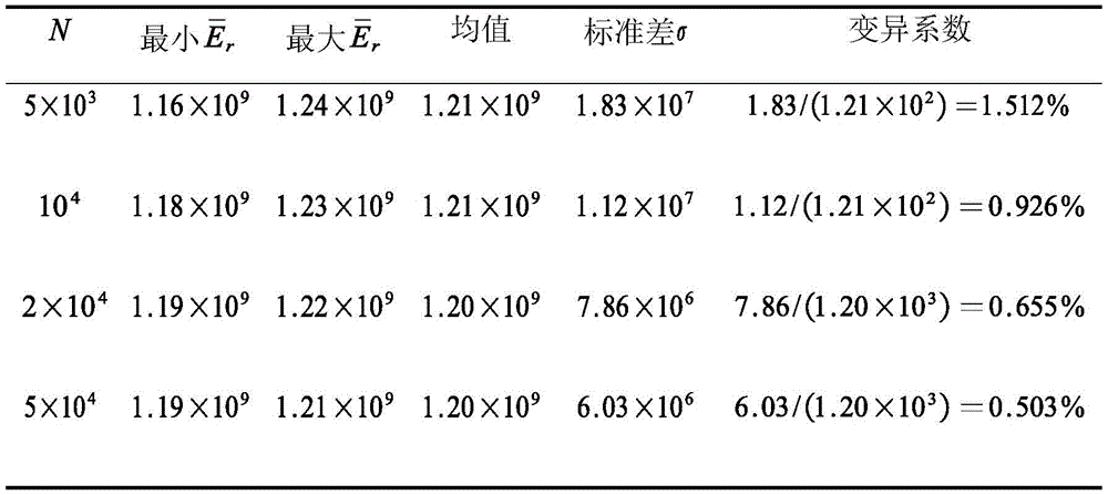
Let θ herei=[α3 β3]=[0° 0°],CθθiEach angle value of [ -35 °, 35 ° [ ]]N is 5X 10 respectively3、104、2×10⁴、5×10⁴And assume arm length L096mm, end effector length Lg110mm, base arm length Lb81mm, 15mm height h of lifting lug, radius r of distributed rope hole027.5mm, and then calculate Each value of N is calculated 30 times, each calculation is independent,
 the results are shown in FIGS. 9a to 9d, where FIG. 9a is a graph of N taken as
 5X 10³The time calculation results, FIG. 9b is N104Time of flight FIG. 9c shows the result of calculation of (2X 10) for N4Time of flight
 FIG. 9d shows the result of calculation of (1), N is
 5X 10⁴Time of flight The calculation result of (2).
The results of the calculations in fig. 9a to 9d were counted as shown in table 3. As can be seen from table 3, when N is 2 × 10⁴In this case, not only the amount of calculation is small, but also the coefficient of variation is small. In consideration of the computational efficiency and computational accuracy, equation (45) is expressed by N being 2 × 10⁴。
TABLE 3 calculation table for corresponding parameters of different N values
If one rope of the rope-driven mechanical arm is broken, the joint controlled by the rope becomes an under-actuated joint, and the remaining two ropes can locally drive the joint. The joint is locally adjusted by the two ropes, so that the global rope degeneration driving cost of the mechanical arm is adjusted to be minimum, and then the under-actuated joint is locked by external force and is not moved any more. Because of the redundancy characteristic of the rope-driven mechanical arm, even if the joint loses the motion capability, the mechanical arm can still complete the rest specified task, but the position adjusted by the joint can keep the average rope driving speed to be minimum in the process of completing the rest task, so that the motion performance of the mechanical arm is optimal.
The method for evaluating the operating performance of the rope-driven flexible mechanical arm provided by the preferred embodiment of the invention has the following advantages:
(1) and providing a performance evaluation index of rope driving cost. The rope driving cost degree provided by the invention comprehensively considers the driving space, the joint space and the working space, comprehensively considers the motion characteristic of the rope driving mechanical arm from the angle of minimizing the rope driving speed, and provides a theoretical reference basis for the control of the rope driving redundant mechanical arm.
(2) And (5) providing a rope degradation driving cost. Aiming at the condition that a controlled joint fails due to breakage of one rope, the invention provides the rope degradation driving cost degree to describe the operation performance of the mechanical arm at the moment, and provides an optimization target for engineering personnel when the rope of the rope-driven mechanical arm breaks.
(3) And (5) providing a global rope degradation driving cost degree and a control strategy after one rope is broken. The invention provides a global rope degradation driving cost degree to describe the influence of a failure joint on the operation performance of a mechanical arm by comprehensively considering various motion conditions of a rope-driven mechanical arm after one rope is broken, and a control strategy after one rope is broken is provided by taking the minimization of the global rope degradation driving cost degree as a target.
The foregoing is a more detailed description of the invention in connection with specific preferred embodiments and it is not intended that the invention be limited to these specific details. For those skilled in the art to which the invention pertains, several equivalent substitutions or obvious modifications can be made without departing from the spirit of the invention, and all the properties or uses are considered to be within the scope of the invention.
Claims (9)
1. The method for evaluating the operating performance of the rope-driven flexible mechanical arm is characterized by comprising the following steps of:
s1: according to the relational expression of the length change rate of the rope in each joint and the angular velocity of the joint, establishing the relational expression for solving the speed of the rope according to the angular velocity of the joint in a numerical integration mode;
s2: based on a DH coordinate system of the mechanical arm, establishing a relational expression for solving linear velocity and angular velocity of the end effector according to the joint angular velocity;
s3: establishing an expression of the rope driving cost degree reflecting the volume of the ellipsoid obtained by mapping the unit ball of the working space of the mechanical arm to the driving space by combining the relational expression of the step S1 and the relational expression of the step S2, and evaluating the operation performance of the mechanical arm according to the expression of the rope driving cost;
wherein the expression of the rope driving cost degree established in step S3 is:

in the formula (I), the compound is shown in the specification,


2. The operability evaluation method according to claim 1, wherein step S3 further includes establishing an expression of a rope-degrading drive cost degree and/or a global rope-degrading drive cost degree to evaluate operability when any one rope of the robot arm breaks, based on the expression of the rope-degrading drive cost degree and/or the global rope-degrading drive cost degree.
3. The method according to claim 1, wherein the robot arm includes a drive base, n arms, n joints, 3n ropes, and an end effector, wherein the n joints are connected between every two adjacent arms and between the endmost arm and the end effector, wherein first ends of the 3n ropes are driven by the drive base, second ends of the 3n ropes sequentially pass through rope passing holes in disks provided at both ends of the arms to be connected to ends of the n joints, wherein each joint is driven by the 3 ropes, wherein both ends of the arms and one end of the end effector are provided with rotation brackets, respectively, and rotation axes of the rotation brackets provided at both ends of each arm are perpendicular to each other, and wherein the arms between the two rotation brackets of every two adjacent arms and the endmost arm and the end effector are provided with rotation brackets, respectively Two of the device are connected to a universal joint through pin shafts to form the joints, and every two of the joints are formed and are perpendicular to each other.
4. The operability evaluation method according to claim 1, wherein the relationship between the length change rate of the rope in each joint and the joint angular velocity in step S1 is:

in the formula, vi,iFor the length change rate of the i-th drive rope in the i-th joint, vi,i+nFor the length change rate of the i + n th drive rope in the i-th joint, vi,i+2nFor the length change rate of the i +2n th drive rope in the i-th joint, li,iVariable length of i-th rope in i-th joint, li,i+nVariable length of i + n rope in i joint, li,i+2nIs the variable length of the i +2n rope in the i-th joint, alphaiIs the pitch angle, beta, of the ith jointiIs the yaw angle, w, of the ith jointiαPitch angle rate for the ith joint; w is aiβThe yaw rate of the ith joint is shown, and n is the number of joints of the mechanical arm.
5. The operability evaluation method according to claim 4, wherein the relation established in step S1 for solving the speed of the rope from the joint angular velocity is:

wherein the content of the first and second substances, vithe rope speed caused by driving the i-th rope by the driving base,
6. the operability evaluation method according to claim 1, wherein the relational expression for solving the linear velocity and the angular velocity of the end effector from the joint angular velocity established in step S2 is:

in the formula, veIs the velocity vector of the end effector, ve=[vex vey vez]T;weIs the angular velocity vector, w, of the end effectore=[wex wey wez]T;wiαPitch angle rate for the ith joint; w is aiβIs the yaw rate of the ith joint,0Ji,vejα∈R6represented is the joint space to working space velocity jacobian of the pitch angle alpha of the joint i,0Ji,vejβ∈R6represented is the joint space to workspace velocity jacobian of the yaw angle beta of the joint i,0Ji,vej=[0Ji,vejα 0Ji,vejβ]∈R6 ×2。
7. the handling performance evaluation method according to claim 1, wherein step S3 further includes establishing an expression of a rope-degradation driving cost degree for evaluating the handling performance when any one rope of the robot arm breaks according to the expression of the rope-degradation driving cost degree, wherein the expression of the rope-degradation driving cost degree when any one rope of the joints i of the robot arm breaks is:

in the formula (I), the compound is shown in the specification,


8. the operation performance evaluation method according to claim 7, wherein step S3 further includes establishing an expression of a global rope degradation drive cost degree for evaluating the operation performance when a certain rope of the robot arm breaks according to the expression of the global rope degradation drive cost degree, wherein the expression of the global rope degradation drive cost degree when any one rope of the joints i of the robot arm breaks is:

in the formula, CθθiRepresenting all angles except pitch and yaw corresponding to the failed joint i, and N represents the number of terms of the numerator sum.
9. A computer-readable storage medium storing computer-executable instructions that, when invoked and executed by a processor, cause the processor to implement the method of evaluating the operational performance of a rope-driven flexible robotic arm of any one of claims 1 to 8.
Priority Applications (1)
| Application Number | Priority Date | Filing Date | Title |
|---|---|---|---|
| CN202110156262.7A CN112959310B (en) | 2021-02-04 | 2021-02-04 | Method for evaluating operating performance of rope-driven flexible mechanical arm |
Applications Claiming Priority (1)
| Application Number | Priority Date | Filing Date | Title |
|---|---|---|---|
| CN202110156262.7A CN112959310B (en) | 2021-02-04 | 2021-02-04 | Method for evaluating operating performance of rope-driven flexible mechanical arm |
Publications (2)
| Publication Number | Publication Date |
|---|---|
| CN112959310A CN112959310A (en) | 2021-06-15 |
| CN112959310B true CN112959310B (en) | 2022-04-19 |
Family
ID=76274010
Family Applications (1)
| Application Number | Title | Priority Date | Filing Date |
|---|---|---|---|
| CN202110156262.7A Active CN112959310B (en) | 2021-02-04 | 2021-02-04 | Method for evaluating operating performance of rope-driven flexible mechanical arm |
Country Status (1)
| Country | Link |
|---|---|
| CN (1) | CN112959310B (en) |
Families Citing this family (1)
| Publication number | Priority date | Publication date | Assignee | Title |
|---|---|---|---|---|
| CN115958611B (en) * | 2023-03-17 | 2023-06-27 | 苏州艾利特机器人有限公司 | Mechanical arm dexterity assessment method, device and storage medium |
Family Cites Families (9)
| Publication number | Priority date | Publication date | Assignee | Title |
|---|---|---|---|---|
| DE202004012584U1 (en) * | 2004-08-10 | 2005-01-05 | Zf Friedrichshafen Ag | A robotic arm for instructional purposes has an exposed assembly including additional linked arms driven by toothed belts in several degrees of freedom |
| EP3095564B1 (en) * | 2015-05-20 | 2018-07-04 | Airbus Defence and Space, S.A. | Robot for inspection of confined spaces |
| CN106393172A (en) * | 2016-11-06 | 2017-02-15 | 浙江大学 | Multi-joint flexible underwater mechanical arm |
| CN106737628A (en) * | 2017-02-14 | 2017-05-31 | 深圳源创智能机器人有限公司 | A kind of flexible charging robot driven based on rope |
| CA2977077C (en) * | 2017-06-16 | 2019-10-15 | Robotiq Inc. | Robotic arm camera system and method |
| CN109176494B (en) * | 2018-09-28 | 2022-03-29 | 哈尔滨工业大学(深圳) | Self-calibration method and system for rope-driven multi-joint flexible robot and storage medium |
| CN109760051B (en) * | 2019-01-16 | 2020-02-07 | 哈尔滨工业大学 | Rope length change determination method for rope-driven super-redundancy degree of freedom robot |
| CN111421531B (en) * | 2020-03-27 | 2022-03-29 | 哈尔滨工业大学(深圳)(哈尔滨工业大学深圳科技创新研究院) | Flexible mechanical arm for redundant backup of driving rope |
| CN111590602A (en) * | 2020-05-20 | 2020-08-28 | 清华大学深圳国际研究生院 | Multi-degree-of-freedom continuous arm based on optical fiber sensing and robot |
-
2021
- 2021-02-04 CN CN202110156262.7A patent/CN112959310B/en active Active
Also Published As
| Publication number | Publication date |
|---|---|
| CN112959310A (en) | 2021-06-15 |
Similar Documents
| Publication | Publication Date | Title |
|---|---|---|
| Liu et al. | A hybrid active and passive cable-driven segmented redundant manipulator: Design, kinematics, and planning | |
| US11077547B2 (en) | Parallel mechanism with kinematically redundant actuation | |
| US9814480B2 (en) | Forceps manipulator and forceps system comprising forceps manipulator | |
| Oh et al. | Cable suspended planar robots with redundant cables: Controllers with positive tensions | |
| CN112936271B (en) | Rope-driven flexible mechanical arm and three-dimensional space statics modeling method thereof | |
| CN112936273A (en) | Speed-level kinematics modeling method of rope-driven flexible mechanical arm | |
| Aref et al. | Geometrical workspace analysis of a cable-driven redundant parallel manipulator: KNTU CDRPM | |
| CN109176488B (en) | Flexible robot kinematics calibration method and system | |
| CN112959310B (en) | Method for evaluating operating performance of rope-driven flexible mechanical arm | |
| Huang et al. | A geometric algebra algorithm for the closed-form forward displacement analysis of 3-PPS parallel mechanisms | |
| Briot et al. | The hidden robot: An efficient concept contributing to the analysis of the controllability of parallel robots in advanced visual servoing techniques | |
| Yang et al. | Self-calibration of three-legged modular reconfigurable parallel robots based on leg-end distance errors | |
| CN109434838B (en) | Coordinated motion planning method and system for endoscopic operation of line-driven continuous robot | |
| CN112415086B (en) | High-altitude metal pipeline flaw detection system based on teleoperation flying mechanical arm | |
| Hesselbach et al. | Direct kinematic singularity detection of a hexa parallel robot | |
| Deashapriya et al. | Biomimetic flexible robot arm design and kinematic analysis of a novel flexible robot arm | |
| Shi et al. | Position and Orientation Control for Hyperelastic Multisegment Continuum Robots | |
| Bruckmann et al. | Wire robot suspension systems for wind tunnels | |
| Wang et al. | The kinematic analysis and stiffness optimization for an 8-DOF cable-driven manipulator | |
| Wang et al. | A novel 2-SUR 6-DOF parallel manipulator actuated by spherical motion generators | |
| Thanh et al. | Determination of constraint wrenches and design of parallel mechanisms | |
| Zhu et al. | Kinematics and Stiffness of Active-Passive Hybrid Cable-Driven Robots: Modeling and Analysis | |
| Itul et al. | 446. On the Kinematics and Dynamics of 3-DOF Parallel Robots with Triangle Platform. | |
| Qin et al. | Error compensation for snake arm maintainer under variable loads | |
| Qi et al. | Modeling, Vibration Control, and Trajectory Tracking of a Kinematically Constrained Planar Hybrid Cable-Driven Parallel Robot |
Legal Events
| Date | Code | Title | Description |
|---|---|---|---|
| PB01 | Publication | ||
| PB01 | Publication | ||
| SE01 | Entry into force of request for substantive examination | ||
| SE01 | Entry into force of request for substantive examination | ||
| GR01 | Patent grant | ||
| GR01 | Patent grant |