CN112955085A - Adjustable rail device for external fixing system - Google Patents
Adjustable rail device for external fixing system Download PDFInfo
- Publication number
- CN112955085A CN112955085A CN201980072615.6A CN201980072615A CN112955085A CN 112955085 A CN112955085 A CN 112955085A CN 201980072615 A CN201980072615 A CN 201980072615A CN 112955085 A CN112955085 A CN 112955085A
- Authority
- CN
- China
- Prior art keywords
- end housing
- clamping
- clamping member
- rotating
- rotating end
- Prior art date
- Legal status (The legal status is an assumption and is not a legal conclusion. Google has not performed a legal analysis and makes no representation as to the accuracy of the status listed.)
- Pending
Links
- 210000000988 bone and bone Anatomy 0.000 claims abstract description 35
- 210000001519 tissue Anatomy 0.000 claims abstract description 10
- 230000006835 compression Effects 0.000 claims description 25
- 238000007906 compression Methods 0.000 claims description 25
- 230000004323 axial length Effects 0.000 claims description 13
- 230000007246 mechanism Effects 0.000 description 14
- 238000000034 method Methods 0.000 description 14
- 230000000712 assembly Effects 0.000 description 8
- 238000000429 assembly Methods 0.000 description 8
- 230000008901 benefit Effects 0.000 description 6
- 230000007423 decrease Effects 0.000 description 2
- 239000000463 material Substances 0.000 description 2
- 238000012986 modification Methods 0.000 description 2
- 230000004048 modification Effects 0.000 description 2
- 239000011295 pitch Substances 0.000 description 2
- 230000003068 static effect Effects 0.000 description 2
- 230000004075 alteration Effects 0.000 description 1
- 230000015572 biosynthetic process Effects 0.000 description 1
- 230000006870 function Effects 0.000 description 1
- 230000013011 mating Effects 0.000 description 1
- 238000010079 rubber tapping Methods 0.000 description 1
- 238000006467 substitution reaction Methods 0.000 description 1
Images


Classifications
-
- A—HUMAN NECESSITIES
- A61—MEDICAL OR VETERINARY SCIENCE; HYGIENE
- A61B—DIAGNOSIS; SURGERY; IDENTIFICATION
- A61B17/00—Surgical instruments, devices or methods, e.g. tourniquets
- A61B17/56—Surgical instruments or methods for treatment of bones or joints; Devices specially adapted therefor
- A61B17/58—Surgical instruments or methods for treatment of bones or joints; Devices specially adapted therefor for osteosynthesis, e.g. bone plates, screws, setting implements or the like
- A61B17/60—Surgical instruments or methods for treatment of bones or joints; Devices specially adapted therefor for osteosynthesis, e.g. bone plates, screws, setting implements or the like for external osteosynthesis, e.g. distractors, contractors
- A61B17/64—Devices extending alongside the bones to be positioned
- A61B17/6466—Devices extending alongside the bones to be positioned with pin-clamps movable along a solid connecting rod
- A61B17/6475—Devices extending alongside the bones to be positioned with pin-clamps movable along a solid connecting rod the connecting rod being threaded
-
- A—HUMAN NECESSITIES
- A61—MEDICAL OR VETERINARY SCIENCE; HYGIENE
- A61B—DIAGNOSIS; SURGERY; IDENTIFICATION
- A61B17/00—Surgical instruments, devices or methods, e.g. tourniquets
- A61B17/56—Surgical instruments or methods for treatment of bones or joints; Devices specially adapted therefor
- A61B17/58—Surgical instruments or methods for treatment of bones or joints; Devices specially adapted therefor for osteosynthesis, e.g. bone plates, screws, setting implements or the like
- A61B17/60—Surgical instruments or methods for treatment of bones or joints; Devices specially adapted therefor for osteosynthesis, e.g. bone plates, screws, setting implements or the like for external osteosynthesis, e.g. distractors, contractors
- A61B17/64—Devices extending alongside the bones to be positioned
- A61B17/6458—Devices extending alongside the bones to be positioned with pin-clamps fixed at ends of connecting element
-
- A—HUMAN NECESSITIES
- A61—MEDICAL OR VETERINARY SCIENCE; HYGIENE
- A61B—DIAGNOSIS; SURGERY; IDENTIFICATION
- A61B17/00—Surgical instruments, devices or methods, e.g. tourniquets
- A61B17/56—Surgical instruments or methods for treatment of bones or joints; Devices specially adapted therefor
- A61B17/58—Surgical instruments or methods for treatment of bones or joints; Devices specially adapted therefor for osteosynthesis, e.g. bone plates, screws, setting implements or the like
- A61B17/60—Surgical instruments or methods for treatment of bones or joints; Devices specially adapted therefor for osteosynthesis, e.g. bone plates, screws, setting implements or the like for external osteosynthesis, e.g. distractors, contractors
- A61B17/64—Devices extending alongside the bones to be positioned
- A61B17/6425—Devices extending alongside the bones to be positioned specially adapted to be fitted across a bone joint
-
- A—HUMAN NECESSITIES
- A61—MEDICAL OR VETERINARY SCIENCE; HYGIENE
- A61B—DIAGNOSIS; SURGERY; IDENTIFICATION
- A61B17/00—Surgical instruments, devices or methods, e.g. tourniquets
- A61B17/56—Surgical instruments or methods for treatment of bones or joints; Devices specially adapted therefor
- A61B17/58—Surgical instruments or methods for treatment of bones or joints; Devices specially adapted therefor for osteosynthesis, e.g. bone plates, screws, setting implements or the like
- A61B17/60—Surgical instruments or methods for treatment of bones or joints; Devices specially adapted therefor for osteosynthesis, e.g. bone plates, screws, setting implements or the like for external osteosynthesis, e.g. distractors, contractors
- A61B17/64—Devices extending alongside the bones to be positioned
- A61B17/6466—Devices extending alongside the bones to be positioned with pin-clamps movable along a solid connecting rod
- A61B17/6483—Devices extending alongside the bones to be positioned with pin-clamps movable along a solid connecting rod the connecting rod having a non-circular section
-
- A—HUMAN NECESSITIES
- A61—MEDICAL OR VETERINARY SCIENCE; HYGIENE
- A61B—DIAGNOSIS; SURGERY; IDENTIFICATION
- A61B17/00—Surgical instruments, devices or methods, e.g. tourniquets
- A61B17/56—Surgical instruments or methods for treatment of bones or joints; Devices specially adapted therefor
- A61B17/58—Surgical instruments or methods for treatment of bones or joints; Devices specially adapted therefor for osteosynthesis, e.g. bone plates, screws, setting implements or the like
- A61B17/60—Surgical instruments or methods for treatment of bones or joints; Devices specially adapted therefor for osteosynthesis, e.g. bone plates, screws, setting implements or the like for external osteosynthesis, e.g. distractors, contractors
- A61B17/66—Alignment, compression or distraction mechanisms
Abstract
Adjustable rail devices and external bone and/or tissue fixation systems including the same are disclosed. The track set includes first and second outer fixed beam members having alignment grooves, and a joint connecting the first and second beam members and configured to selectively adjust the relative angular and rotational arrangements of the first and second beam members. The joint further includes first and second beam-end housings rotationally fixed to the first and second outer fixed beam elements, respectively. The joint further includes first and second clamp members axially and rotationally fixed to the first and second beam-end housings, respectively. The joint further includes first and second rotating end housings coupled to the first and second clamping members, respectively, the first and second rotating end housings being selectively rotatably adjustable relative to the first and second clamping members, respectively, over a fixed range of rotation.
Description
Cross Reference to Related Applications
The present application perfects and claims the benefit of U.S. provisional patent application No.62/727,116 entitled "adjustable track set for external fixation system" filed on 5.9.2018, the entire contents of which are expressly incorporated herein by reference.
Technical Field
The present application relates generally to rails for external bone fixation systems and related methods. More particularly, the present application relates to an adjustable track for an external bone fixation system that allows adjustability between orientations between two or more track portions and related methods.
Background
External fixation devices have been used to treat bone and tissue conditions by positioning bone or tissue segments in desired relative positions based on specific clinical needs. One form of external fixation is a fixation based on a single-sided or single-sided rail. These devices typically consist of a rail or beam member that serves as the structural backbone of the device, along which a clamp assembly is slidably connected that can accept a fixation element (e.g., a bone fixation pin or wire). In some embodiments, the clamp assemblies can be statically locked to the rail, or dynamically driven or axially translated along the rail. In some embodiments, the clamp assembly may rotate about the track and/or be angled relative to the axis of the track.
When configured as a bone or tissue fixation system, some external fixation systems typically include multiple clamp assemblies. In the most basic configuration, there is one static clamp assembly and one drivable clamp assembly connected to the beam member. In some embodiments, a beam element and clamp assembly arranged in this manner may be connected to a second beam and clamp assembly by using a joint element having one or more degrees of freedom (e.g., a hinge having one degree of freedom to a ball or universal joint having three degrees of freedom). However, the beam elements themselves are typically linear and static (i.e., cannot be adjusted outside of a linear shape or path). Thus, the relative positioning and orientation between two or more clips attached to a rail is limited by the linear nature of the rail. Furthermore, adding or removing additional segments or extensions of the components and/or rails of the clip assembly to fit a particular anatomical or fixation arrangement can be cumbersome and/or time consuming.
Accordingly, there is a need for an external bone fixation rail and external bone fixation system having a rail with two or more rail segments and joints that can be selectively adjusted to adjust the orientation between the rail segments to facilitate optimal fixation of bone elements by a clamp connected to the rail segments (and thus the respective bone or bone segments).
Disclosure of Invention
In one aspect, the present application provides an external fixation system comprised of a longitudinal rail or beam arrangement that receives and guides a plurality of clamp assemblies (of the same or different configurations) that may be positioned at different locations and/or orientations relative to the rail. The track set may include a plurality of track segments having adjustable joints connecting and extending between adjacent segments. The track segments may include axial engagement features (e.g., threaded or ribbed tracks) extending along the length or axis of the track segments that serve as a driving engagement point for each clamp assembly. The engagement features are configured to allow the clamp assembly to be locked in place along the axis or length of the respective track segment and selectively driven or translated along the respective track segment. Each rail segment may further include an axially extending alignment groove, and the central bore of the at least one drivable tie down cleat assembly includes an anti-rotation member extending into the alignment groove to rotationally secure the at least one drivable tie down cleat assembly and the beam segment/element about the axis of the beam segment.
In another aspect, the present application provides a joint arrangement for connecting and selectively adjusting the relative angular and rotational arrangements of first and second outer fixed beam elements. The apparatus includes a first beam-end housing including a sleeve portion configured to be rotationally fixed to a first outer fixed beam element and a column portion; a first screw for axially fixing the first beam-end housing to the first outer fixed beam element; a first clamping member axially and rotatably fixed to the column portion of the first outer fixed beam element; and a first rotating end housing including a rotating portion and a post connected with the first clamping member, the first rotating end housing being selectively rotatably adjustable relative to the first clamping member within a fixed range of rotation. The apparatus also includes a second beam-end housing including a sleeve portion configured to be rotationally fixed to the second outer fixed beam element and a post portion; a second screw for axially fixing the second beam-end housing to the second outer fixed beam element; a second clamping member axially and rotatably fixed to the pillar portion of the second outer fixed beam element; and a second rotating end housing including a rotating portion and a post connected with the second clamping member, the second rotating end housing being selectively rotatably adjustable relative to the second clamping member within a fixed range of rotation. The rotating portions of the first and second rotating-end housings are rotatably connected around a rotating shaft. The first clamping member includes a compression screw for selectively applying a compressive force to selectively rotatably secure the first rotating end housing to the first clamping member, and the second clamping member includes a compression screw for selectively applying a compressive force to selectively rotatably secure the second rotating end housing to the second clamping member.
In some embodiments, the first beam-end housing, the first clamping member, and the first rotating end housing include an aperture that forms a channel extending from the rotating portion of the first rotating end housing to the first screw. In some embodiments, the first beam-end housing, the first clamping member, the first rotating end housing, and the second rotating end housing include bores forming channels extending from the rotating portion of the first rotating end housing to the second screw in a first relative orientation of the first rotating end housing and the second rotating end housing about the axis of rotation. In some embodiments, the axis of rotation intersects the axes of the first and second screws. In some embodiments, the axis of rotation is oriented perpendicular to the axes of the first and second screws.
In another aspect, the present application provides an adjustable track set comprising: a first elongate outer fixation element defining a first axis and including a first axially extending threaded track portion; a second elongate outer fixation element defining a second axis and including a second axially extending threaded track portion; and a joint arrangement as disclosed herein connecting the first and second elongated outer fixed beam elements.
In some embodiments, the axis of rotation intersects the axes of the first and second elongated outer fixed beam elements. In some embodiments, the axis of rotation is oriented perpendicular to the axes of the first and second elongated external fixation beam elements.
In another aspect, the present application provides an external bone and/or tissue fixation system comprising an adjustable rail apparatus disclosed herein; and at least one actuatable fixation clamp assembly coupled to one of the first elongated outer fixation beam element and the second elongated outer fixation beam element.
In another aspect, the present application provides an adjustable track set. This adjustable rail set includes: an elongated first outer fixed beam member including a first shaft and an outer surface with an alignment groove; an elongated outer fixed beam member including a second shaft, an outer surface with an alignment groove; and a joint connecting the first and second beam members and configured to selectively adjust the relative angular and rotational arrangement of the first and second beam members. The joint includes a first beam-end housing including a column portion rotationally fixed to a first outer fixed beam element and a sleeve portion; a first screw axially securing the first beam-end housing to the first outer fixed beam element; a first clamping member axially and rotationally fixed to the column portion of the first beam-end housing; and a first rotating end housing including a rotating portion and a post connected with the first clamping member, the first rotating end housing being selectively rotatably adjustable relative to the first clamping member within a fixed range of rotation. The joint further includes a second beam-end housing including a post portion rotationally fixed to the second outer fixed beam element and a sleeve portion; a second screw axially securing the second beam-end housing to the second outer fixed beam element; a second clamping member axially and rotationally fixed to the post portion of the second beam-end housing; and a second rotating end housing including a rotating portion and a post connected with the second clamping member, the second rotating end housing being selectively rotatably adjustable relative to the second clamping member within a fixed range of rotation. The rotating portions of the first and second rotating end housings are rotationally fixed and pivotally connected at an angle about a third axis that is angled relative to the first and second axes of the first and second outer fixed beam elements, respectively. The first clamping member includes a first compression screw for selectively applying a compressive force to the post of the first rotating end housing to selectively rotatably and axially secure the first clamping member and the first rotating end housing. The second clamping member includes a second compression screw for selectively applying a compressive force to the post of the second rotating end housing to selectively rotatably and axially secure the second clamping member and the second rotating end housing.
In some embodiments, the first beam end housing, the first clamping member, and the first rotating end housing include a first bore forming a first channel extending from the rotating portion of the first rotating end housing to the first screw. In some embodiments, the first beam-end housing, the first clamping member, the first rotating end housing, and the second rotating end housing include a second bore forming a second channel extending from the rotating portion of the first rotating end housing to the second screw in a first relative orientation of the first rotating end housing and the second rotating end housing about the axis of rotation.
In some embodiments, the third axis intersects the first axis and the second axis. In some embodiments, the third axis is oriented perpendicular to the first axis and the second axis.
In some embodiments, the first end of the first outer fixed beam element is positioned within the opening of the sleeve portion of the first beam-end housing, and the joint further includes a first pin member connected to the sleeve portion and including a portion that extends within the opening of the sleeve portion and along a portion of the alignment groove of the first outer fixed beam element to be rotationally fixed to the first beam-end housing and the first outer fixed beam element. In some such embodiments, the first end portion of the first beam member includes an internally threaded axial bore, the first beam end housing includes an axial bore extending through the post portion thereof to the opening of the sleeve portion thereof, and the first screw includes an externally threaded shaft portion that is threaded within the internally threaded axial bore of the first end portion of the first beam member. In some such embodiments, the first screw further includes a head defining a cross-sectional dimension greater than a cross-sectional dimension of a portion of the axial bore of the first beam-end housing, thereby preventing the head from passing axially therethrough to axially secure the first beam-end housing and the first outer securing beam member.
In some embodiments, the first clamping member includes an internally threaded bore including a first end portion threadedly connected with the post portion of the first beam end housing and including a first slot having a width corresponding to a width of the first pin member, and the first pin member further includes a portion extending axially along an outer side of the post portion of the first beam end housing and within the first slot of the threaded bore of the first clamping member to rotationally and axially secure the first clamping member and the first beam end housing. In some such embodiments, the internally threaded bore of the first clamping member further includes a second end portion threadedly connected with the post of the first rotating end housing and including a first unthreaded recess having a width wider than a width of a second pin member connected to the first rotating end housing, and the second pin member includes a portion extending axially along an outer side of the post of the first rotating end housing and located within the first unthreaded recess of the threaded bore of the first clamping member, thereby selectively permitting a limited range of relative rotation between the first clamping member and the first rotating end housing. In some such embodiments, the first clamping member includes a compression slot extending along an entire axial length of the first clamping member from an outer side thereof to an internally threaded bore, and a pair of first clamping portions having substantially aligned clamping bores on opposite sides of the compression slot, and the joint further includes a first compression screw extending within the clamping bores of the first clamping portions and threadedly connected with at least one of the clamping bores of the first clamping portions such that rotation of the first clamping screw about its axis in a first direction draws the first clamping portions toward one another and inwardly deforms the internally threaded bore of the first clamping member such that the first clamping member exerts a compressive force on the post portion of the first rotation end housing to selectively rotatably secure the first clamping member and the first rotation end housing, and rotation of the first clamping screw about its axis in a second direction opposite the first direction allows the internally threaded bore of the first clamping member to deform outwardly such that the first clamping member exerts little or no compressive force on the post portion of the first rotating end housing, thereby selectively allowing a limited range of relative rotation between the first clamping member and the first rotating end housing. In some such embodiments, the rotating portions of the first and second rotating end housings are pivotably connected by a joint pin defining a third axis. In some such embodiments, the first and second rotating end housings include a split flange yoke pivotally connected by a joint pin and a shaft portion located within the split flange yoke.
In some embodiments, the rotating portions of the first and second rotating end housings are pivotably connected by a joint pin defining a third axis. In some such embodiments, the rotating portions of the first and second rotating end housings include a split flange yoke pivotally connected by a joint pin and a shaft portion located within the split flange yoke.
In some embodiments, the second end of the second outer fixed beam element is located within an opening of a sleeve portion of the second beam-end housing, and the joint further includes a third pin member connected to the sleeve portion and including a portion that extends within the opening of the sleeve portion and along a portion of the alignment groove of the second outer fixed beam element, thereby being rotationally fixed to the second beam-end housing and the second outer fixed beam element. In some such embodiments, the second end portion of the second beam member includes an internally threaded axial bore, the second beam-end housing includes an axial bore extending through the post portion thereof to the opening of the sleeve portion thereof, and the second screw includes an externally threaded shaft portion that is threaded within the internally threaded axial bore of the second end portion of the second beam member. In some such embodiments, the second screw further includes a head defining a cross-sectional dimension greater than a cross-sectional dimension of a portion of the axial bore of the second beam-end housing, thereby preventing the head from passing axially therethrough to axially secure the second beam-end housing and the second external fixation beam element. In some such embodiments, the second clamping member includes an internally threaded bore including a first end threadedly connected with the post portion of the second beam end housing and including a second slot having a width corresponding to a width of the third pin member, and the third pin member further includes a portion extending axially along an outer side of the post portion of the second beam end housing and within the first slot of the threaded bore of the second clamping member to rotationally and axially secure the second clamping member and the second beam end housing. In some such embodiments, the internally threaded bore of the second clamping member further includes a second end portion threadedly connected with the post portion of the second rotation end housing and including a second unthreaded recess having a width wider than a width of a fourth pin member connected to the second rotation end housing, and the fourth pin member includes a portion extending axially along an outer side of the post portion of the second rotation end housing and located within the second unthreaded recess of the threaded bore of the second clamping member to selectively permit relative rotation within a limited range between the second clamping member and the second rotation end housing. In some such embodiments, the second clamping member includes a compression slot extending from an outer side thereof along an entire axial length of the second clamping member to the internally threaded bore, and a pair of second clamping portions having substantially aligned clamping bores on opposite sides of the compression slot, and the joint further includes a second compression screw extending within the clamping bore of the second clamping portion and threadedly connected with at least one clamping bore of the second clamping portion such that rotation of the second clamping screw about its axis in a first direction draws the second clamping portions toward one another and inwardly deforms the internally threaded bore of the second clamping member such that the second clamping member exerts a compressive force on the post portion of the second rotation end housing to selectively rotatably secure the second clamping member and the second rotation end housing, and rotation of the second clamping screw about its axis in a second direction opposite the first direction allows the second clamping member to rotate about its axis in a second direction The internally threaded bore of the tightening member is deformed outwardly such that the second clamping member exerts little or no compressive force on the post portion of the second rotation end housing to selectively permit a limited range of relative rotation between the second clamping member and the second rotation end housing. In some such embodiments, the first clamping member includes an internally threaded bore including a first end portion threadedly connected with the post portion of the first beam end housing and including a first slot having a width corresponding to a width of the first pin member, and the first pin member further includes a portion extending axially along an outer side of the post portion of the first beam end housing and within the first slot of the threaded bore of the first clamping member to rotationally and axially secure the first clamping member and the first beam end housing. In some such embodiments, the internally threaded bore of the first clamping member further includes a second end portion threadedly connected with the post of the first rotating end housing and including a first unthreaded recess having a width wider than a width of a second pin member connected to the first rotating end housing, and the second pin member includes a portion extending axially along an outer side of the post of the first rotating end housing and located within the first unthreaded recess of the threaded bore of the first clamping member to selectively permit a limited range of relative rotation between the first clamping member and the first rotating end housing. In some such embodiments, the first clamping member includes a compression slot extending from an outer side thereof along an entire axial length of the first clamping member to the internally threaded bore, and a pair of first clamping portions having substantially aligned clamping bores on opposite sides of the compression slot, and the joint further includes a first compression screw extending within the clamping bores of the first clamping portions and threadedly connected with at least one of the clamping bores of the first clamping portions such that rotation of the first clamping screw about its axis in a first direction draws the first clamping portions toward one another and inwardly deforms the internally threaded bore of the first clamping member such that the first clamping member exerts a compressive force on the post portion of the first rotation end housing to selectively rotatably secure the first clamping member and the first rotation end housing, and rotation of the first clamping screw about its axis in a second direction opposite the first direction allows the first clamping member to rotate about its axis in a second direction opposite the first direction The internally threaded bore of the clamping member is outwardly deformed such that the first clamping member exerts little or no compressive force on the post portion of the first rotating end housing to selectively permit a limited range of relative rotation between the first clamping member and the first rotating end housing.
In another aspect, the present application provides an external bone and/or tissue fixation system. The fixation system includes an adjustable rail set as described above, and at least one drivable fixation clamp assembly connected to one of the first and second outer fixation beam elements.
In some embodiments, the at least one drivable fixed clamp assembly is configured to axially translate along one of the first and second outer fixed beam elements via an axially extending track portion of an outer surface thereof. In some such embodiments, the axially extending track portion includes external threads or a pattern engaging track. In some embodiments, at least one drivable fixed clamp assembly is rotationally fixed to one of the first and second outer fixed beam elements by its alignment groove.
These and other objects, features and advantages of the present application will become apparent from the following detailed description of the various aspects of the present application when taken in conjunction with the accompanying drawings.
Drawings
To illustrate the adjustable rails, external bone and/or tissue fixation systems, and related fixation methods described herein, exemplary embodiments are provided. These illustrative embodiments are in no way limiting as to the precise configuration, arrangement, and operation of the disclosed adjustable rail, external bone and/or tissue fixation system, and related fixation methods, and other similar embodiments are contemplated.
Fig. 1 shows a perspective view of an exemplary beam element of an external fixation system according to the present application.
FIG. 2 illustrates an end view of the exemplary beam member of FIG. 1 according to the present application.
Fig. 3 illustrates a side view of the exemplary beam element of fig. 1 according to the present application.
Fig. 4 illustrates a cross-sectional side view of the exemplary beam member of fig. 1 according to the present application.
FIG. 5 illustrates an enlarged cross-sectional view of a portion of the exemplary beam element of FIG. 1 as shown in FIG. 4 according to the present application.
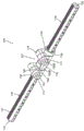
Fig. 6 illustrates a front perspective view of an adjustable track arrangement for an external fixation system according to the present application, the arrangement including a pair of the example beam members of fig. 1-5 connected in a linear arrangement by an example adjustable hinge.
FIG. 7 illustrates a side view of the example adjustable track set of FIG. 6 in a linear arrangement according to the present application.
Fig. 8 illustrates a front perspective view of the example adjustable track set of fig. 6 in a non-linear arrangement according to the present application.
Fig. 9 illustrates a bottom perspective view of the example adjustable track set of fig. 6 in a non-linear arrangement according to the present application.
FIG. 10 illustrates another side view of the example adjustable track set of FIG. 6 in a linear arrangement according to the present application.
FIG. 11 illustrates a top view of the example adjustable track set of FIG. 6 in a linear arrangement according to the present application.
FIG. 12 illustrates a side cross-sectional view of the example adjustable track set of FIG. 6 in a linear arrangement according to the present application.
FIG. 13 illustrates a front perspective view of an exemplary adjustable hinge of the adjustable track device of FIG. 6 in a non-linear arrangement according to the present application.
FIG. 14 illustrates a top view of the example adjustable hinge of FIG. 13 in a linear arrangement according to the present application.
FIG. 15 illustrates an end view of the example adjustable hinge of FIG. 13 in a linear arrangement according to the present application.
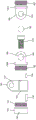
FIG. 16 illustrates an exploded side view of a portion of the example adjustable track set of FIG. 6 including an example adjustable hinge according to the present application.
FIG. 17 illustrates an exploded front perspective view of a portion of the example adjustable track set of FIG. 6 including an example adjustable hinge according to the present application.
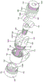
FIG. 18 illustrates an exploded front perspective view of a portion of an example adjustable hinge of the example adjustable track set of FIG. 6 according to the present application.
Fig. 19 illustrates an exploded front perspective view of another portion of an example adjustable hinge of the example adjustable track set of fig. 6 according to the present application.
Fig. 20 illustrates an exploded side view of a portion of an example adjustable hinge of the example adjustable track set of fig. 6 according to the present application.
Fig. 21 illustrates an exploded perspective view of a portion of an example adjustable hinge of the example adjustable track set of fig. 20 according to the present application.
Fig. 22 illustrates an exploded front perspective view of a portion of an example adjustable hinge of the example adjustable track set of fig. 20 according to the present application.
FIG. 23 illustrates a perspective view of the example adjustable track set of FIG. 6 in a non-linear arrangement according to the present application.
Fig. 24 illustrates a front perspective view of a portion of the example adjustable track set of fig. 6, including an example hinge thereof, in a non-linear arrangement according to the present application.
Fig. 25 illustrates a top view of a portion of the example adjustable track set of fig. 6, including an example hinge thereof, in a non-linear arrangement according to the present application.
Fig. 26 illustrates a top view of another portion of the example adjustable track set of fig. 6, including an example hinge thereof, in a non-linear arrangement according to the present application.
Detailed Description
When introducing elements of various embodiments of the present application, the articles "a," "an," "the," and "said" are intended to mean that there are one or more of the elements. The terms "comprising," "including," and "having" are intended to be inclusive and mean that there may be additional elements other than the listed elements. Any examples of parameters do not exclude other parameters of the disclosed embodiments. The components, aspects, features, configurations, arrangements, uses, etc. described, illustrated or otherwise disclosed herein with respect to any particular embodiment are equally applicable to any other embodiment disclosed herein.
As shown in fig. 6-26, the present application provides an external bone or tissue fixation system and associated fixation method 100. The fixation system and method 100 includes one or more independently drivable clamp assemblies (not shown) (which may provide at least 3 degrees of freedom), each of which may translate or be driven along a rail segment 132A, 132B … 132N of the rail device 130. In some other embodiments (not shown), the fixation system and method 100 may include at least one fixed rotatable end clamp assembly (which may provide at least 2 degrees of freedom) located at a free end of one of the rail segments 132A, 132B … 132N. The fixation system and method 100 of fig. 6-26 may be configured or particularly advantageous for use with relatively small bones, such as bones of the hand or foot. For example, the fixation systems and methods 100 of fig. 6-26 may be configured or particularly advantageous for fixing two or more small bones or bone segments of one or more relatively small bones, such as one or more bones or bone segments of a hand or foot, relative to one another. In some embodiments, as shown in fig. 6-26, the fixation system and associated fixation method 100 may be configured to, or particularly advantageous for, repairing a fracture or deformity of one or more bones, such as one or more relatively small bones in the hand or foot. However, the fixation system and associated fixation method 100 may also be configured or particularly advantageous for fixing two or more relatively long bones or bone segments of one or more relatively long bones, such as one or more bones or bone segments of an arm or leg, relative to each other.
Accordingly, the present application provides an external bone fixation system that provides relative movement of two or more bones or bone segments with respect to each other. The system may include movable and drivable clamp assemblies positioned along the axial length of the track elements 130 (provided that connection of at least one non-movable clamp assembly 120 is permitted), and the relative orientation between the track elements 130 may be adjustable or movable relative to each other through the use of a joint mechanism 127 (such as, but not limited to, a joint that provides for adjustment of the angle between the axes of the track elements 130 and/or the orientation of the track elements 130 about their axes), as shown in fig. 1-12.
As shown in fig. 1-12, the beam segments or elements 130 (to which at least one drivable clamp assembly and/or at least one stationary clamp assembly may be connected) may include axially extending or axially elongated beams 130, each beam defining an axis or linear length along a first direction. At least one drivable clamp assembly is translatably or drivably connected to an exterior of each beam member 130, e.g., a plurality of drivable clamp assemblies 110 are translatably connected to an exterior of beam members 130, spaced along the axis or axial length of beam members 130. For example, exemplary fixation systems and methods including at least a pair of beam members 130 may be positioned in a first configuration in which the major axes of the beam members 130 (and thus the clamp assemblies connected thereto) are aligned (e.g., collinear and/or co-oriented about their axes). According to such a first configuration, the joint between the beam elements 130 may be adjusted such that a pair of beam elements 130 are repositioned to a second configuration in which the major axes of the beam elements 130 (and thus the clamp assemblies connected thereto) are offset from one another (e.g., the axes are angled with respect to one another and/or differently oriented about their axes).
As described above, in some embodiments, at least one actuatable clamp assembly may pass through the beam member 130. In other words, in some embodiments, the beam elements 130 may extend through at least one actuatable clamp assembly, and the at least one actuatable clamp assembly may be configured to translate along or over an outer surface of at least the respective beam element 130.
As shown in fig. 1-12, the beam member 130 may be at least generally cylindrical and define an outer surface (e.g., a generally cylindrical outer surface having opposing bases or free ends) that surrounds the shaft and extends between substantially opposing free ends. At least one end of beam member 130 may include a bore or hole 132, with bore or hole 132 extending at least substantially axially into beam member 130 from the end face, as shown in fig. 1-12. The axially extending bore 132 may extend along an axial length of the beam member 130, at least partially (in an axial direction) into an interior or intermediate portion of the beam member 130. The at least one end aperture 132 of the beam member 130 may include internal threads such that the at least one end aperture 132 includes a threaded aperture 132. As shown in fig. 1-12, the at least one end aperture 132 may thus be configured to threadably engage or mate with the external threads of the bolt portion of the end clamp assembly. Similarly, at least one end aperture 132 may thus be configured to threadably engage or mate with an external thread of another beam member 130 or hinge or connection mechanism (e.g., a double threaded hinge or connection mechanism) to removably connect the ends of a pair of beam members 130. Thus, the beam arrangement 100 can be effectively axially elongated by the additional beam member. In other embodiments, the beam member 130 and/or at least one end aperture 132 of the beam member 130 may be unthreaded, or include other configurations or mechanisms in addition to internal threads for mating with the rotatable end clamp assembly 120 and/or additional beam members.
As shown in fig. 1-12, the outer surface of the beam member 130 may be generally cylindrical and include external threads or pattern engaging tracks 131 and alignment grooves or slots 133. The external threads or pattern engagement tracks 131 and/or alignment grooves 133 may extend the entire length of the beam member 130 along the axial length of the outer surface of the beam member 130, or partially along the length of the beam member 130. As shown in fig. 1-12, the engagement rail 131 may be retracted or recessed into the beam member 130. In this way, the tracks 131 may form grooves extending radially into the beam member 130 or within the beam member 130. The engagement track 131 may form a portion of the outer surface of the beam member 130. In some embodiments, as shown in fig. 4-8, the engagement track 131 may be a groove defined by a radius. As shown in fig. 4-8, the track 131 may include external threads (or internal threads, depending on the viewing angle) or other surface features that extend along the axial length of the track 131. The threads of the engagement track 131 may cooperate with the threads of the drive member of the drivable clamp assembly to allow the drivable clamp assembly to be axially translated or driven along the length of the beam element 130 by the drive member. As such, the pitch of the threads of the engagement track 131 and the threads of the drive member of the drivable clamp assembly may have compatible pitches and/or other configurations. In some embodiments, engagement track 131 may be a hemispherical threaded groove extending into beam member 130. It should be noted that such radially or semi-spherically grooved thread engagement tracks 131 can be machined relatively easily. For example, the hemispherical grooved thread engagement track 131 may be machined by a ball nose mill, which alleviates the difficulties associated with tapping relatively long section holes, as opposed to a standard 60 or trapezoidal thread, for example. However, engagement track 131 may include any threaded design and/or other surface features to allow the clamp assembly to be locked or secured to beam member 130 and/or driven axially along beam member 130.
As also shown in fig. 1-12, similar to the engagement rail 131, the alignment groove 133 may be indented or recessed into the beam member 130. As such, alignment groove 133 may form a groove that extends radially into beam member 130 or within beam member 130. Alignment groove 133 may form a portion of the outer surface of beam member 130. In some embodiments, as shown in fig. 1-12, the alignment groove 133 may be defined by a radius, such as a hemispherical groove. In other embodiments, the alignment groove 133 may be any other shape or configuration. The alignment groove 133 may be coupled with an alignment member (e.g., a pin or ball bearing) of the drivable clamp assembly to allow the drivable clamp assembly 110 (via the drive member and the engagement track 131) to translate or drive axially along the length of the beam member 130 while being aligned or positioned at a particular orientation about the axis of the beam member 130, as will be explained further below. The alignment groove 133 may thus function as a linear, partially cylindrical groove for providing anti-rotation of the drivable clamp assembly about the beam element 130, as will be explained further below. The alignment groove 133 and the drivable clamp assembly may only be engaged by the alignment member in a particular relative direction between the drivable clamp assembly and the beam element 130, and the drivable clamp assembly may be prevented from rotating about the beam element 130 from that direction (but allowed to translate or slide axially along the alignment groove 133 when driven axially by its driving member).
In some embodiments, the beam member 130 may include an intermediate outer surface portion 134 extending between the alignment groove 133 and the engagement rail 131 portion of the beam member 130, as shown in fig. 1-12. In some embodiments, the alignment groove 133 and the engagement track 131 portion of the beam member 130 may be substantially opposite each other about the axis of the beam member 130, and thus two substantially similar intermediate outer surface portions 134 may extend therebetween. In other embodiments, the alignment groove 133 and engagement track 131 portions of the beam member 130 may be offset about the axis of the beam member 131. As shown in fig. 1-12, the intermediate outer surface portion 134 may be a substantially smooth surface (e.g., a non-threaded surface), and may be curved or arcuate. In some embodiments, intermediate outer surface portion 134 may be a cylindrical surface portion (e.g., a convex surface defined by a single radius) that extends around the axis of beam member 130 and/or along the axial length of beam member 130.
As shown in the first linear and aligned configuration of beam members 130 of adjustable beam apparatus 125 shown in fig. 6 and 7, hinge mechanism 127 allows a user to adjust or configure the angle of the axes of beam members 130 relative to each other and/or the relative orientation of beam members 130 about their axes (relative to each other) as compared to the second non-linear/angled and rotated configuration of beam members 130 of adjustable beam apparatus 125 of fig. 3 and 4 shown in fig. 8 and 9.
As shown in fig. 6-26, the hinge mechanism 127 can include a beam-end housing 152 axially fixed or connected to the end 132 of the beam member 130. For example, as shown in fig. 4, 5, 12-22, 25, and 26, the beam-end housing 152 may include a through-hole configured to allow the threaded post portion of the cap screw 154 to extend therethrough and threadably connect with the threaded bore 132 extending into the end portion of the respective beam member 130. The through-hole of the spar-end housing 152 may also be configured to prevent the head of the cap screw 154 from (axially) moving/translating therethrough. The head of the cap screw 154 may also include a rotational recess, hole, protrusion, or other feature that allows the cap screw 154 to be engaged and rotated or torqued (about its axis) to screw the threaded post portion extending through/past the hole of the beam-end housing 152 into the internal bore 132 of the corresponding beam member 130.
As shown in fig. 6-26, the hinge mechanism 127 can be configured or arranged such that the cap screw 154 is captured or received within the beam-end housing 152, and its rotational features can be accessed through access holes 199A, 199B in at least one opposing configuration or arrangement of the hinge mechanism 127 (e.g., along the axis of rotation of the cap screw 154 via one or more through-holes), as shown in fig. 23-26, such that the hinge mechanism 127 can be connected between/to the ends 132 of a pair of beam members 130, as described further below. Thus, the hinge mechanism 127 can be initially provided separate or disconnected from the pair of beam members 130 and then connected thereto by screwing (by rotation) the cap screw 154 into the interior bore 132 of the beam member 130.
As shown in fig. 6-26, the beam-end housing 152 can include a sleeve portion 156, the sleeve portion 156 extending at least partially around an outer surface of the end 132 of the beam member 130 (e.g., when the adjustment hinge 127 is coupled thereto by a cap screw 154). As shown in fig. 12, 13, and 16-22, the sleeve portion 156 of the beam-end housing 152 may include a protrusion or pin 158 that engages within the groove 133 of the beam member 130 (e.g., when the adjustment hinge 127 is connected thereto by the cap screw 154) to rotationally lock the beam-end housing 152 and the beam member 130 together (i.e., prevent the beam-end housing 152 from rotating about the axis of the respective beam member 130). As shown in fig. 12, 13, and 16-22, in one exemplary embodiment, the protrusion 158 may comprise a pin or similar member that is positioned or captured within and extends from a hole or slot in the inner surface of the sleeve portion 156 of the beam end housing 152.
The sleeve portion 156 and the protrusion 158 of the beam-end housing 152 may be configured to translate axially onto the end 132 of the beam member 130 (i.e., to threadably connect with the internally threaded axial bore of the end 132 of the beam member 130) by rotation of the cap screw 154 such that the end 132 of the beam member 130 is received/positioned within the sleeve portion 156 and the protrusion 158 is located within the recess 133 of the beam member 130. The beam-end housings 152 may thus be axially and rotationally fixed relative to the respective beam members 130.
As shown in fig. 6-26, adjustment hinge 127 may also include a pair of split collars 160. As shown in fig. 12 and 16-22, each split clamp ring 160 includes an internally threaded axial bore 162, the internally threaded axial bore 162 configured to threadably mate with an externally threaded post portion 164 of the respective beam-end housing 152 and an externally threaded post portion 182 of the respective rotating- end housing 180A, 180B to axially secure (via the respective cap screw 154) each clamp ring 160 with the respective beam-end housing 152, the respective rotating- end housing 180A, 180B, and the respective beam member 130. As shown in fig. 12 and 16-22, the threaded post portion 164 of the spar-end housing 152 is disposed/positioned at one axial end of the spar-end housing 152 and the sleeve portion 156 thereof is disposed/positioned at the other axial end of the spar-end housing 152.
As shown in fig. 12, 17-19, 21 and 22, the distal axial side of the threaded bore 162 of each clamp collar 160 may include a recess or unthreaded portion 166 (when the externally threaded post portion 164 of the respective spar cap housing 152 is threadably coupled with the distal axial side of the threaded bore 162) that the recess or unthreaded portion 166 mates with a protrusion or pin 158 mounted on/associated with the respective spar cap housing 152. For example, as shown in fig. 12, 17-19, 21 and 22, each beam-end housing 152 may be configured with holes and/or slots that receive a projection or pin 158, the projection or pin 158 extending partially inside/inboard of the sleeve portion 156 and outside/outboard of the post portion 164. As shown in fig. 12, 17-19, 21 and 22, the recess or unthreaded portion 166 of the threaded bore 162 of the clamp ring 160 and the portion of the projection or pin 158 mounted outside of/associated with the threaded post portion 164 of the beam end housing 152 are configured such that the clamp ring 160 and the beam end housing 152 are rotationally fixed (about the axis of the beam member 130) when the projection 158 is located within the recess 166. For example, the width of the recess or unthreaded portion 166 of the threaded bore 162 of the clamp ring 160 may match or substantially correspond to the width of the protrusion or pin 158 mounted on/associated with the outside of the threaded post portion 164 of the beam-end housing 152.
Similarly, as shown in fig. 12, 16-19, 21 and 22, the proximal axial side of the threaded bore 162 of each clamp collar 160 may include a recess or unthreaded portion 168 (when the externally threaded post portion 182 of the respective rotating end housing 180A, 180B is threaded with the proximal axial side of the threaded bore 162), which recess or unthreaded portion 168 engages a protrusion or pin 196 mounted on/associated with the threaded post portion 182 of the respective rotating end housing 180A, 180B. For example, as shown in fig. 12, 16-19, 21 and 22, the threaded post portion 182 of each rotating end housing 180A, 180B may be configured with a hole and/or slot that receives a projection or pin 196, which projection or pin 196 extends partially outside of the post portion 182. As shown in fig. 12, 16-19, 21 and 22, the recess or unthreaded portion 168 of the threaded bore 162 of the clamp collar 160 and the portion of the projection or pin 196 mounted on/associated with the outer side of the threaded post portion 182 of the rotating end housing 180A, 180B are configured such that when the projection or pin 196 is located within the recess or unthreaded portion 168, only limited relative rotation of the respective rotating end housing 180A, 180B (and thus about the axis of the beam member 130) within the bore 162 of the clamp collar 160 is provided. For example, as shown in fig. 17, 18, 21 and 22, the width of the recess or unthreaded portion 168 of the threaded bore 162 of the clamp ring 160 can be substantially greater than or longer than the width of a protrusion or pin 196 mounted on/associated with the outer side of the threaded post portion 182 of the respective rotating end housing 180A, 180B. As such, the relative rotational arrangement or orientation of the associated beam member 130 with respect to the respective rotating end housing 180A, 180B (and, thus, the pivot or rotation point or axis, as will be further explained below) may be adjusted or selected within the range provided for/by the recess 168 by relative rotation (e.g., about the axis thereof) of the respective clamping member 160, beam end housing 156, and beam member 130.
When a particular relative rotational arrangement or orientation of the beam member 130 and the respective rotating end housings 180A, 180B is selected or achieved, for example, relative to the joint 127 (e.g., a pivot or rotation point or axis of the joint 127, as will be explained further below) and/or the respective clamp ring 160, the respective split clamp ring 160 can be used to selectively lock that particular rotational arrangement. As shown in fig. 6-26, the split collet 160 includes a gripping portion 170, the gripping portion 170 being separated by a gap or split that passes along the entire axial length of the collet 160 from the exterior of the collet 160 to the central bore 162. As shown in fig. 6-26, the clamping portions 170 may include substantially aligned through-holes having axes extending through gaps between the clamping portions 170. As shown in fig. 6-26, at least one through-hole of the clamping portion 170 may be threaded, and the through-hole may be configured to mate with a clamping or compression screw 172. The clamp ring 160 and the clamp screw 172 may be configured such that as the clamp screw 172 is rotated or axially advanced into/through the bore of the clamp portion 170 and through the gap of the clamp ring 160, the clamp portion 170 is drawn together and the central bore 162 is compressed (i.e., the diameter or width of its central bore 162 becomes smaller) such that the clamp ring 160 applies a compressive force to the associated threaded post 164 of the respective rotating end housing 180A, 180B to rotationally fix (e.g., about the axis of the associated beam member 130) the associated threaded post 164 of the respective rotating end housing 180A, 180B and the respective clamp ring 160.
Thus, as described above, when the clamp ring 160 is rotationally fixed to the respective beam-end housing 156 and its associated beam member 130, the relative rotational arrangement or orientation of the respective beam member 130 with respect to the respective rotating end housing 180A, 180B (and thus the pivot or rotational point or axis of the joint 127, as will be further explained below) may be selectively fixed by a clamping or compressive force applied by the clamp ring 160 to the threaded post portion 164 of the respective rotating end housing 180A, 180B. Conversely, by reducing (or eliminating) the clamping or compressive force applied to the threaded post portion 164 of the respective rotating end housing 180A, 180B by the clamp collar 160 (via rotation of the clamp screw 172) and rotating the respective beam member 130 (and associated clamp collar 160 and beam end housing 152 rotationally secured thereto) about its axis relative to the respective rotating end housing 180A, 180B (and thus the pivot or rotation point or axis of the joint 127, as will be further explained below), the relative rotational arrangement or orientation of the respective beam member 130 relative to the respective rotating end housing 180A, 180B (and thus the pivot or rotation point or axis of the joint 127, as will be further explained below) may be selectively provided or adjusted.
In some embodiments, the split clamp ring 160 may be deformed by rotation of the clamp screw 172 such that the clamping portions 170 move closer toward each other (i.e., the gap decreases) and thereby the diameter or other dimension of the central bore 162 decreases to apply a compressive force to the threaded post portion 164 of the respective beam-end housing 152 and the threaded post portion 164 of the respective rotating end housing 180A, 180B (to rotationally fix the components).
As shown in fig. 12-14 and 16-22, the rotating end housings 180A, 180B each include a joint or rotating portion 186 rotatably or pivotally connected or mated by at least one joint pin 192 extending through aligned apertures 188 thereof. As shown in fig. 12-14 and 16-22, the rotating portion 186 of the rotating end housing 180A, 180B and the at least one joint pin 192 may form a U-shaped joint such that the second rotating end housing 180B includes a "U" shaped or split flange yoke and the first rotating end housing 180A forms a shaft portion that fits within and rotates within the rotating end housing 180B (or vice versa). At least one joint pin 192 (e.g., at least one stepped pin) may extend through the bore 188 of the rotating portion 186 of the second rotating end housing 180B and at least partially through the bore 188 of the rotating portion 186 of the first rotating end housing 180A. The at least one pin 192 may rotationally fix the rotating portions 186 of the first and second rotating end housings 180A and 180B together, but allow pivoting or angular rotation therebetween along an axis that is angled relative to the axis of the beam member 130. For example, at least one joint pin 192 may secure the rotating portions 186 of the first and second rotating end housings 180A and 180B together (and thereby secure the associated beam members 130 together) along the axis of the associated beam members 130, but allow angular/pivotal movement therebetween (and thus between the associated beam members 130) about the axis of the at least one joint pin 192, as shown by the arrangement of the joint 127 in fig. 6 and 7 in comparison to fig. 8 and 9.
The angular movement or rotation between the rotating portions 186 of the first and second rotating end housings 180A, 180B provided by the at least one joint pin 192, and thus the associated beam member 130 (i.e., the axis of the at least one joint pin 192), is thereby angled relative to the axis of the associated beam member 130. In some embodiments, the axis of angular movement or rotation between the first and second rotating end housings 180A and 180B (i.e., the axis of the at least one joint pin 192) (and thus between the associated beam elements 130) intersects the axis of the associated beam elements 130. In some embodiments, the angular motion or axis of rotation (i.e., the axis of the at least one joint pin 192) between the first and second rotating end housings 180A and 180B (and thus between the associated beam elements 130) is oriented orthogonal or perpendicular to the axis of the associated beam elements 130.
As also shown in fig. 6-26, the first rotating end housing 180A can include a first connection hole 199A and a second connection hole 199B extending therethrough from the rotating portion 186. The first connection aperture 199A of the first rotating end housing 180A may be at least partially aligned with the axis captured within the associated beam end housing 152 to which the cap screw 154 is connected. Similarly, the associated beam end housing 152 can further include a first connection hole 199A that is at least partially aligned with the first connection hole 199A of the first rotating end housing 180A and the shaft captured therein to which the cap screw 154 is connected. As such, when the hinge mechanism 127 is configured/arranged (e.g., the angular orientation of the beam member 130 is configured/arranged) such that the first connection hole 199A at the rotating portion 186 of the first rotating end housing 180A is exposed or accessible, as shown in fig. 23-25, a tool can be inserted through the first connection hole 199A and engaged with the cap screw 154 to apply a torque thereto, and ultimately the cap screw 154 (and thus the first rotating end housing 180A and the hinge mechanism 127 as a whole) can be threaded or disconnected from the end hole 132 of the first beam member 130.
Similarly, as shown in fig. 23, 24 and 26, in a particular arrangement or rotational arrangement of the first and second rotation end housings 180A and 180B about the axis of rotation (and thus a particular angular orientation of the beam member 130), the second connection aperture 199B of the first rotation end housing 180A may be at least partially aligned with the axis of the cap screw 154 connection captured within the beam end housing 152 associated with the second rotation end housing 180B. As shown in fig. 23, 24 and 26, the second rotating end housing 180B and associated beam end housing 152 can further include a second attachment aperture 199B that is at least partially aligned with the shaft captured therein to which the cap screw 154 is attached and the second attachment aperture 199A of the first rotating end housing 180A. As such, when the hinge mechanism 127 is configured/arranged (e.g., the angular orientation of the beam member 130 is configured/arranged) such that the second connection aperture 199B at the rotation portion 186 of the first rotation end housing 180A is at least partially aligned with the connected cap screw 154 associated with the second rotation end housing 180A, as shown in fig. 23, 24, and 26, a tool may be inserted through the second connection aperture 199B of the first and second rotation end housings 180A and 180B and the associated beam end housing 152 and engaged with the connected cap screw 154 to apply a torque thereto and ultimately to thread or disconnect the cap screw 154 (and thus the second rotation end housing 180B and the hinge mechanism 127 as a whole) from the end aperture 132 of the second beam member 130.
It is to be understood that the above description is intended to be illustrative, and not restrictive. Numerous changes and modifications may be made herein by one of ordinary skill in the art without departing from the general spirit and scope of the application as defined by the following claims and the equivalents thereof. For example, the above-described embodiments (and/or aspects thereof) may be used in combination with each other. In addition, many modifications may be made to adapt a particular situation or material to the teachings of the various embodiments without departing from their scope. While the dimensions and types of materials described herein are intended to define the parameters of the various embodiments, they are by no means limiting and are merely exemplary. Many other embodiments will be apparent to those of skill in the art upon reviewing the above description. The scope of various embodiments should, therefore, be determined with reference to the appended claims, along with the full scope of equivalents to which such claims are entitled. In the appended claims, the terms "including" and "in which" are used as the plain-english equivalents of the respective terms "comprising" and "wherein". Furthermore, in the appended claims, the terms "first," "second," and "third," etc. are used merely as labels, and do not impose numerical requirements on their objects. Moreover, the term "operably linked" is used herein to refer to a connection that results from the joining of separate and distinct components, either directly or indirectly, and the formation of an integral (i.e., one-piece) component. Furthermore, the limitations of the following claims are not written in a functionally defined format, nor are they to be construed based on 35u.s.c. § 112 sixth paragraph, unless such claim limitations explicitly use the word "for … …", followed by a functional description without other structure. It is to be understood that not necessarily all such objects or advantages described above may be achieved in accordance with any particular embodiment. Thus, for example, those skilled in the art will recognize that the systems and techniques described herein may be embodied or carried out in a manner that achieves or optimizes one advantage or group of advantages as taught herein without necessarily achieving other objects or advantages as may be taught or suggested herein.
While the application has been described in detail in connection with only a limited number of embodiments, it should be readily understood that the application is not limited to such disclosed embodiments. But can be modified to incorporate any number of variations, alterations, substitutions or equivalent arrangements not heretofore described, but which are commensurate with the spirit and scope of the application. Additionally, while various embodiments of the application have been described, it is to be understood that aspects of the application may include only some of the described embodiments. Accordingly, the application is not to be seen as limited by the foregoing description, but is only limited by the scope of the appended claims.
This written description uses examples to disclose the application, including the best mode, and also to enable any person skilled in the art to practice the application, including making and using any devices or systems and performing any incorporated methods. The scope of the patent of the present application is defined by the claims and may include other examples that occur to those skilled in the art. Such other examples are intended to be within the scope of the claims if they have structural elements that do not differ from the literal language of the claims, or if they include equivalent structural elements with insubstantial differences from the literal languages of the claims.
Claims (28)
1. An adjustable track set comprising:
an elongated first outer fixed beam member including a first shaft and an outer surface having an alignment groove;
an elongated second outer fixed beam member including a second shaft and an outer surface having an alignment groove; and
a joint connecting first and second beam members and configured to selectively adjust relative angular and rotational arrangements of the first and second beam members, the joint comprising:
a first beam-end housing including a column portion rotationally fixed to the first outer fixed beam element and a sleeve portion;
a first screw axially securing the first beam-end housing to the first outer fixed beam element;
a first clamping member axially and rotationally fixed to the column portion of the first beam-end housing;
a first rotating end housing including a rotating portion and a post connected with the first clamping member, the first rotating end housing being selectively rotatably adjustable relative to the first clamping member within a fixed range of rotation;
a second beam-end housing including a column portion rotationally fixed to the second outer fixed beam element and a sleeve portion;
a second screw axially securing the second beam-end housing to the second outer fixed beam element;
a second clamping member axially and rotationally fixed to the post portion of the second beam-end housing; and
a second rotating end housing including a rotating portion and a post connected with the second clamping member, the second rotating end housing being selectively rotatably adjustable relative to the second clamping member within a fixed range of rotation;
wherein the rotating portions of the first and second rotating end housings are rotationally fixed and pivotally angularly connected about third axes, respectively, that are angled relative to the first and second axes of the first and second outer fixed beam elements;
wherein the first clamping member comprises a first compression screw for selectively applying a compressive force to a post portion of the first rotating end housing to selectively rotatably and axially secure the first clamping member and the first rotating end housing; and
wherein the second clamping member comprises a second compression screw for selectively applying a compressive force to the post portion of the second rotating end housing to selectively rotatably and axially secure the second clamping member and the second rotating end housing.
2. The fitting of claim 1, wherein the first beam end housing, the first clamping member, and the first rotating end housing include a first bore forming a first channel extending from a rotating portion of the first rotating end housing to the first screw.
3. The joint of claim 1 or 2, wherein the first beam end housing, the first clamping member, the first rotating end housing, and the second rotating end housing comprise a second bore forming a second channel extending from a rotating portion of the first rotating end housing to the second screw in a first relative orientation of the first and second rotating end housings about an axis of rotation.
4. The joint of claim 1, wherein the third axis intersects the first and second axes.
5. The joint of claim 1 or 4, wherein the third axis is oriented perpendicular to the first and second axes.
6. The joint of claim 1, wherein the first end of the first outer fixed beam element is positioned within an opening of a sleeve portion of the first beam-end housing, and wherein the joint further comprises a first pin member connected to the sleeve portion and including a portion extending within the opening of the sleeve portion and along a portion of the alignment groove of the first outer fixed beam element to rotationally fix to the first beam-end housing and the first outer fixed beam element.
7. The fitting of claim 6, wherein the first end portion of the first beam member includes an internally threaded axial bore, wherein the first beam end housing includes an open axial bore extending through the post portion thereof to the sleeve portion thereof, and wherein the first screw includes an externally threaded shaft portion that is threaded within the internally threaded axial bore of the first end portion of the first beam member.
8. The fitting of claim 7, wherein the first screw further includes a head defining a cross-sectional dimension that is greater than a cross-sectional dimension of a portion of the axial bore of the first beam-end housing, thereby preventing the head from passing axially therethrough to axially secure the first beam-end housing and the first outer securing beam element.
9. The fitting according to any one of claims 6 to 8, wherein the first clamping member includes an internally threaded bore including a first end portion threadedly connected with the first beam end housing post portion and including a first slot having a width corresponding to a width of the first pin member, and wherein the first pin member further includes a portion extending axially along an outer side of the first beam end housing post portion and within the first slot of the first clamping member threaded bore to rotationally and axially secure the first clamping member and the first beam end housing.
10. The fitting of claim 9, wherein the internally threaded bore of the first clamping member further includes a second end portion threadedly coupled with the post portion of the first rotating end housing and including a first unthreaded recess having a width wider than a width of a second pin member coupled to the first rotating end housing, and wherein the second pin member includes a portion extending axially along an outer side of the post portion of the first rotating end housing and within the first unthreaded recess of the threaded bore of the first clamping member to selectively permit a limited range of relative rotation between the first clamping member and the first rotating end housing.
11. The fitting of claim 10, wherein the first clamping member includes a compression slot extending from an exterior thereof to the internally threaded bore along an entire axial length of the first clamping member, and a pair of first clamping portions having substantially aligned clamping bores on opposite sides of the compression slot, and wherein the fitting further includes a first compression screw extending within the clamping bores of the first clamping portion and threadedly connected with at least one clamping bore of the first clamping portion such that rotation of the first clamping screw about its axis in a first direction draws the first clamping portions toward one another and inwardly deforms the internally threaded bore of the first clamping member such that the first clamping member exerts a compressive force on the post portion of the first rotating end housing, to selectively rotatably secure the first clamping member and the first rotating end housing, and rotation of the first clamping screw about its axis in a second direction opposite the first direction allows the internally threaded bore of the first clamping member to deform outwardly such that the first clamping member exerts little or no compressive force on the post portion of the first rotating end housing to selectively allow a limited range of relative rotation between the first clamping member and the first rotating end housing.
12. The joint of claim 11, wherein the rotating portions of the first and second rotating end housings are pivotably connected by a joint pin defining the third axis.
13. The joint of claim 12 wherein the rotating portions of the first and second rotating end housings comprise a split flange yoke and a shaft portion pivotally connected by the joint pin, the shaft portion being located within the split flange yoke.
14. The joint of claim 1, wherein the rotating portions of the first and second rotating end housings are pivotably connected by a joint pin defining the third axis.
15. The joint of claim 14 wherein the rotating portions of the first and second rotating end housings comprise a split flange yoke and a shaft portion pivotally connected by the joint pin, the shaft portion being located within the split flange yoke.
16. The joint of any of claims 6 to 8, wherein the second end of the second outer fixing beam element is located within an opening of a sleeve portion of the second beam end housing, and wherein the joint further comprises a third pin member connected to the sleeve portion and including a portion extending within the opening of the sleeve portion and along a portion of the alignment groove of the second outer fixing beam element to be rotationally fixed to the second beam end housing and the second outer fixing beam element.
17. The joint of claim 16, wherein the second end portion of the second beam member includes a female threaded axial bore, wherein the second beam-end housing includes an open axial bore extending through the post portion thereof to the sleeve portion thereof, and wherein the second screw includes a male threaded shaft portion that is threaded into the female threaded axial bore of the second end portion of the second beam member.
18. The fitting of claim 17, wherein the second screw further comprises a head defining a cross-sectional dimension that is greater than a cross-sectional dimension of a portion of the axial bore of the second beam-end housing, thereby preventing the head from passing axially therethrough to axially secure the second beam-end housing and the second external fixation beam element.
19. The fitting of claim 18, wherein the second clamping member includes an internally threaded bore including a first end that is threadedly connected with the post portion of the second spar end housing and includes a second slot having a width that corresponds to a width of the third pin member, and wherein the third pin member further includes a portion that extends axially along an outer side of the post portion of the second spar end housing and within the first slot of the threaded bore of the second clamping member to rotationally and axially secure the second clamping member and the second spar end housing.
20. The fitting of claim 19, wherein the internally threaded bore of the second clamping member further includes a second end portion threadedly coupled with the post portion of the second rotating end housing and including a second unthreaded recess having a width wider than a width of a fourth pin member coupled to the second rotating end housing, and wherein the fourth pin member includes a portion extending axially along an outer side of the post portion of the second rotating end housing and within the second unthreaded recess of the threaded bore of the second clamping member to selectively permit a limited range of relative rotation between the second clamping member and the second rotating end housing.
21. The fitting according to claim 20, wherein the second clamping member includes a compression groove extending from an outer side thereof to the internally threaded bore along an entire axial length of the second clamping member, and a pair of second clamping portions having substantially aligned clamping bores on opposite sides of the compression groove, and wherein the fitting further includes a second compression screw extending within the clamping bores of the second clamping portion and threadedly connected with at least one clamping bore of the second clamping portion such that rotation of the second clamping screw about an axis thereof in a first direction draws the second clamping portions toward each other and inwardly deforms the internally threaded bore of the second clamping member such that the second clamping member exerts a compressive force on the post portion of the second rotating end housing, to selectively rotatably secure the second clamping member and the second rotating end housing, and rotation of the second clamping screw about its axis in a second direction opposite the first direction allows the internally threaded bore of the second clamping member to deform outwardly such that the second clamping member exerts little or no compressive force on the post portion of the second rotating end housing to selectively allow a limited range of relative rotation between the second clamping member and the second rotating end housing.
22. The fitting of claim 21, wherein the first clamping member includes an internally threaded bore including a first end that is threadedly connected with the post portion of the first beam end housing and includes a first slot having a width that corresponds to a width of the first pin member, and wherein the first pin member further includes a portion that extends axially along an outer side of the post portion of the first beam end housing and within the first slot of the threaded bore of the first clamping member to rotationally and axially secure the first clamping member and the first beam end housing.
23. The fitting of claim 22, wherein the internally threaded bore of the first clamping member further includes a second end portion threadedly coupled with the post of the first rotating end housing and including a first unthreaded recess having a width wider than a width of a second pin member coupled to the first rotating end housing, and wherein the second pin member includes a portion extending axially along an outer side of the post of the first rotating end housing and within the first unthreaded recess of the threaded bore of the first clamping member to selectively permit a limited range of relative rotation between the first clamping member and the first rotating end housing.
24. The fitting according to claim 23, wherein the first clamping member includes a compression groove extending from an outer side thereof to the internally threaded bore along an entire axial length of the first clamping member, and a pair of first clamping portions having substantially aligned clamping bores on opposite sides of the compression groove, and wherein the fitting further includes a first compression screw extending within the clamping bores of the first clamping portion and threadedly connected with at least one clamping bore of the first clamping portion such that rotation of the first clamping screw about an axis thereof in a first direction draws the first clamping portions toward each other and inwardly deforms the internally threaded bore of the first clamping member such that the first clamping member exerts a compressive force on the post portion of the first rotating end housing, to selectively rotatably secure the first clamping member and the first rotating end housing, and rotation of the first clamping screw about its axis in a second direction opposite the first direction allows the internally threaded bore of the first clamping member to deform outwardly such that the first clamping member exerts little or no compressive force on the post portion of the first rotating end housing to selectively allow a limited range of relative rotation between the first clamping member and the first rotating end housing.
25. An external bone and/or tissue fixation system comprising:
an adjustable track arrangement as claimed in any one of claims 1 to 24; and
at least one actuatable mounting fixture assembly coupled to one of the first outer mounting beam member and the second first outer mounting beam member.
26. The fixation system according to claim 25, wherein the at least one drivable fixation clamp assembly is configured to axially translate along one of the first and second first outer fixation beam elements via an axially extending track portion of an outer surface thereof.
27. The fixation system of claim 26, wherein the axially extending track portion comprises external threads or a pattern engaging track.
28. The securing system of claim 25, wherein the at least one drivable securing clip assembly is rotationally secured to one of the first and second first outer securing beam elements by its alignment groove.
Applications Claiming Priority (3)
| Application Number | Priority Date | Filing Date | Title |
|---|---|---|---|
| US201862727116P | 2018-09-05 | 2018-09-05 | |
| US62/727,116 | 2018-09-05 | ||
| PCT/US2019/049828 WO2020051384A1 (en) | 2018-09-05 | 2019-09-05 | Adjustable rail apparatus for external fixation systems |
Publications (1)
| Publication Number | Publication Date |
|---|---|
| CN112955085A true CN112955085A (en) | 2021-06-11 |
Family
ID=69723254
Family Applications (1)
| Application Number | Title | Priority Date | Filing Date |
|---|---|---|---|
| CN201980072615.6A Pending CN112955085A (en) | 2018-09-05 | 2019-09-05 | Adjustable rail device for external fixing system |
Country Status (8)
| Country | Link |
|---|---|
| US (1) | US20210186562A1 (en) |
| EP (1) | EP3846707A4 (en) |
| JP (1) | JP2021536308A (en) |
| CN (1) | CN112955085A (en) |
| AU (1) | AU2019335016A1 (en) |
| BR (1) | BR112021004093A2 (en) |
| CA (1) | CA3111335A1 (en) |
| WO (1) | WO2020051384A1 (en) |
Families Citing this family (2)
| Publication number | Priority date | Publication date | Assignee | Title |
|---|---|---|---|---|
| US11737786B2 (en) | 2019-12-31 | 2023-08-29 | Orthopediatrics Corp. | Multiple track system for positioning of bone segments |
| US20230173957A1 (en) * | 2021-12-02 | 2023-06-08 | Safran Seats Usa Llc | Mounting system for seat frame structure |
Citations (12)
| Publication number | Priority date | Publication date | Assignee | Title |
|---|---|---|---|---|
| WO1991011149A1 (en) * | 1990-02-05 | 1991-08-08 | Anthony Philip Pohl | Improvements in and to an external fixation device |
| US5846245A (en) * | 1995-10-20 | 1998-12-08 | New York University | Bone-adjusting device |
| US20030105460A1 (en) * | 2000-03-15 | 2003-06-05 | Dennis Crandall | Multidirectional pivoting bone screw and fixation system |
| CN101208168A (en) * | 2005-05-02 | 2008-06-25 | 布林克曼产品公司 | Quick-change mechanism for use with the stationary spindle of a Davenport(r) automatic screw machine |
| US20100030273A1 (en) * | 2008-02-26 | 2010-02-04 | Spartek Medical, Inc. | Versatile polyaxial connector assembly and method for dynamic stabilization of the spine |
| WO2010077309A2 (en) * | 2008-12-17 | 2010-07-08 | Nutek Orthopaedics, Inc. | External fixation apparatus with adjustable pin clamping means and convergent bone pins |
| CN101876394A (en) * | 2010-06-25 | 2010-11-03 | 胡安武 | Universal turning bench multifunctional bracket |
| US20100312243A1 (en) * | 2008-02-08 | 2010-12-09 | Texas Scottish Rite Hospital For Children | External fixator ring |
| US20110172666A1 (en) * | 2010-01-08 | 2011-07-14 | Heilman Benjamin P | Variable angle locking screw |
| CN103596511A (en) * | 2011-05-17 | 2014-02-19 | 新特斯有限责任公司 | Telescoping screw for femoral neck fractures |
| CN106641506A (en) * | 2015-08-17 | 2017-05-10 | 胜赛斯光谱责任有限公司 | Pipe coupling having double-threaded tightening fastener and associated methods |
| WO2017151822A1 (en) * | 2016-03-01 | 2017-09-08 | Amdt Holdings, Inc. | External bone fixation systems |
Family Cites Families (6)
| Publication number | Priority date | Publication date | Assignee | Title |
|---|---|---|---|---|
| GB2280608A (en) * | 1993-08-05 | 1995-02-08 | Hi Shear Fasteners Europ Ltd | External bone fixator |
| IT1278856B1 (en) * | 1995-09-19 | 1997-11-28 | Orthofix Srl | ACCESSORY FOR EXTERNAL FIXER |
| US7507240B2 (en) | 2005-03-18 | 2009-03-24 | Ron Anthon Olsen | Adjustable splint for osteosynthesis |
| GB2519981B (en) * | 2013-11-02 | 2015-09-23 | Ali Abdullah Mohammed | Sliding external fixator |
| US9867637B2 (en) * | 2014-10-01 | 2018-01-16 | Foot Innovations, Llc | Clamping device for use with an anatomic external fixation device |
| CN106725783B (en) * | 2017-01-08 | 2019-05-17 | 北京工业大学 | A kind of elbow joint external fixator |
-
2019
- 2019-09-05 CN CN201980072615.6A patent/CN112955085A/en active Pending
- 2019-09-05 EP EP19856630.9A patent/EP3846707A4/en active Pending
- 2019-09-05 JP JP2021512636A patent/JP2021536308A/en active Pending
- 2019-09-05 AU AU2019335016A patent/AU2019335016A1/en active Pending
- 2019-09-05 CA CA3111335A patent/CA3111335A1/en active Pending
- 2019-09-05 WO PCT/US2019/049828 patent/WO2020051384A1/en unknown
- 2019-09-05 BR BR112021004093-5A patent/BR112021004093A2/en unknown
-
2021
- 2021-03-03 US US17/190,803 patent/US20210186562A1/en active Pending
Patent Citations (12)
| Publication number | Priority date | Publication date | Assignee | Title |
|---|---|---|---|---|
| WO1991011149A1 (en) * | 1990-02-05 | 1991-08-08 | Anthony Philip Pohl | Improvements in and to an external fixation device |
| US5846245A (en) * | 1995-10-20 | 1998-12-08 | New York University | Bone-adjusting device |
| US20030105460A1 (en) * | 2000-03-15 | 2003-06-05 | Dennis Crandall | Multidirectional pivoting bone screw and fixation system |
| CN101208168A (en) * | 2005-05-02 | 2008-06-25 | 布林克曼产品公司 | Quick-change mechanism for use with the stationary spindle of a Davenport(r) automatic screw machine |
| US20100312243A1 (en) * | 2008-02-08 | 2010-12-09 | Texas Scottish Rite Hospital For Children | External fixator ring |
| US20100030273A1 (en) * | 2008-02-26 | 2010-02-04 | Spartek Medical, Inc. | Versatile polyaxial connector assembly and method for dynamic stabilization of the spine |
| WO2010077309A2 (en) * | 2008-12-17 | 2010-07-08 | Nutek Orthopaedics, Inc. | External fixation apparatus with adjustable pin clamping means and convergent bone pins |
| US20110172666A1 (en) * | 2010-01-08 | 2011-07-14 | Heilman Benjamin P | Variable angle locking screw |
| CN101876394A (en) * | 2010-06-25 | 2010-11-03 | 胡安武 | Universal turning bench multifunctional bracket |
| CN103596511A (en) * | 2011-05-17 | 2014-02-19 | 新特斯有限责任公司 | Telescoping screw for femoral neck fractures |
| CN106641506A (en) * | 2015-08-17 | 2017-05-10 | 胜赛斯光谱责任有限公司 | Pipe coupling having double-threaded tightening fastener and associated methods |
| WO2017151822A1 (en) * | 2016-03-01 | 2017-09-08 | Amdt Holdings, Inc. | External bone fixation systems |
Also Published As
| Publication number | Publication date |
|---|---|
| JP2021536308A (en) | 2021-12-27 |
| CA3111335A1 (en) | 2020-03-12 |
| EP3846707A4 (en) | 2022-06-08 |
| BR112021004093A2 (en) | 2021-06-22 |
| AU2019335016A1 (en) | 2021-04-15 |
| EP3846707A1 (en) | 2021-07-14 |
| WO2020051384A1 (en) | 2020-03-12 |
| US20210186562A1 (en) | 2021-06-24 |
Similar Documents
| Publication | Publication Date | Title |
|---|---|---|
| US11471192B2 (en) | External bone fixation systems | |
| US6171308B1 (en) | Method and apparatus for external fixation of large bones | |
| US11006976B2 (en) | External bone fixation systems | |
| US6520961B1 (en) | Method and apparatus for external fixation of a hinged joint | |
| KR20090092802A (en) | Keyed crown orientation for multi-axial screws | |
| US20210186562A1 (en) | Adjustable rail apparatus for external fixation systems | |
| US20220133357A1 (en) | Strut assemblies and external fixation systems | |
| US11969191B2 (en) | External bone fixation struts and systems |
Legal Events
| Date | Code | Title | Description |
|---|---|---|---|
| PB01 | Publication | ||
| PB01 | Publication | ||
| SE01 | Entry into force of request for substantive examination | ||
| SE01 | Entry into force of request for substantive examination |