CN1129484A - Signal level indicator and associated method - Google Patents
Signal level indicator and associated method Download PDFInfo
- Publication number
- CN1129484A CN1129484A CN95190557A CN95190557A CN1129484A CN 1129484 A CN1129484 A CN 1129484A CN 95190557 A CN95190557 A CN 95190557A CN 95190557 A CN95190557 A CN 95190557A CN 1129484 A CN1129484 A CN 1129484A
- Authority
- CN
- China
- Prior art keywords
- lighted
- led
- visual element
- signal
- signal level
- Prior art date
- Legal status (The legal status is an assumption and is not a legal conclusion. Google has not performed a legal analysis and makes no representation as to the accuracy of the status listed.)
- Pending
Links
- 238000000034 method Methods 0.000 title claims description 20
- 230000000007 visual effect Effects 0.000 claims description 26
- 238000009434 installation Methods 0.000 claims description 11
- 230000008859 change Effects 0.000 claims description 5
- GOLXNESZZPUPJE-UHFFFAOYSA-N spiromesifen Chemical compound CC1=CC(C)=CC(C)=C1C(C(O1)=O)=C(OC(=O)CC(C)(C)C)C11CCCC1 GOLXNESZZPUPJE-UHFFFAOYSA-N 0.000 claims description 3
- 230000001413 cellular effect Effects 0.000 description 13
- 238000010586 diagram Methods 0.000 description 5
- 230000008878 coupling Effects 0.000 description 3
- 238000010168 coupling process Methods 0.000 description 3
- 238000005859 coupling reaction Methods 0.000 description 3
- 238000005457 optimization Methods 0.000 description 3
- 230000008569 process Effects 0.000 description 3
- 230000035807 sensation Effects 0.000 description 3
- 244000287680 Garcinia dulcis Species 0.000 description 1
- 230000005540 biological transmission Effects 0.000 description 1
- 238000006243 chemical reaction Methods 0.000 description 1
- 230000000694 effects Effects 0.000 description 1
- 230000005284 excitation Effects 0.000 description 1
- 238000001914 filtration Methods 0.000 description 1
- 230000006870 function Effects 0.000 description 1
- 238000004519 manufacturing process Methods 0.000 description 1
- 230000002688 persistence Effects 0.000 description 1
- 238000005070 sampling Methods 0.000 description 1
- 238000003860 storage Methods 0.000 description 1
Images


Classifications
-
- H—ELECTRICITY
- H04—ELECTRIC COMMUNICATION TECHNIQUE
- H04B—TRANSMISSION
- H04B17/00—Monitoring; Testing
- H04B17/30—Monitoring; Testing of propagation channels
- H04B17/309—Measuring or estimating channel quality parameters
-
- H—ELECTRICITY
- H04—ELECTRIC COMMUNICATION TECHNIQUE
- H04B—TRANSMISSION
- H04B17/00—Monitoring; Testing
- H04B17/20—Monitoring; Testing of receivers
- H04B17/23—Indication means, e.g. displays, alarms, audible means
Abstract
A signal level indicator (204, 304) utilizes illuminating each of a number of (for example five) light-emitting diodes (LED) (314-318, 414-418) for an individual period of time. The number of LEDs to be illuminated and the individual period of time that each is to be illuminated varies with the magnitude of the input signal (421).
Description
The present invention relates to signal level indicator, be specifically related to improve the method and apparatus of signal level indicator efficient.
User's demand has promoted the scientific-technical progress of person in electronics.Exploitation that industry member is positive and production had impelled electronic component to get over miniaturization already, and had caused occurring quite light and the limited hand-held portable electronic device of size.This device is typically battery-powered.The operation persistence of this electronic installation is based on the life-span of associated batteries, and this has become the basic starting point when the user promotes the sale of products.In order to use battery to greatest extent to satisfy user's requirement, must make it the power consumption optimization by these electronic installations of exploitation, also do not damage the functional of user's sensation.
The user buys before the electronic installation, but will assess the operation characteristic of these electronic installations and relevant user's sense quality earlier usually.For example, the user to buy this telephone set operation characteristic of being considered before the portable honeycomb telephone set be to measure battery allowed continuous " air time " amount or " standby time " relevant with this portable honeycomb telephone set operation.
But important user's sense quality (for example need to utilize a visual element that has and comprehensively the display in electronic installation show service data to the user) relevant with operation characteristic.For example, but portable honeycomb telephone set is equipped with to such an extent that a vision indication of a contiguous cellular basestation communication validity can be provided to the user usually.These a plurality of visual element of normally utilizing a kind of bar chart tabular form to arrange realize, promptly light these visual element in regular turn according to the size or the intensity of the control signal that receives from this vicinity cellular basestation.This sampling device of visual display unit is called signal level indicator or S meter.
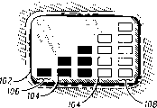
The comprehensively level indicator 100 in light emitting diode (LED) display 102 of a kind of prior art of Fig. 1 example.The signal level indicator 100 of this prior art contains five row LED unit, and every row have for example LED104 of a LED unit at least.The signal level indicator 100 of this prior art visually shows the relative intensity of received signal, and promptly first row 106 from least significant bit (LSB) begin to finish to light in order the LED unit that each is listed as to the 5th row 108 of highest significant position.Like this, high-intensity signal receives will light whole five row LED unit, and the first row LED106 is only lighted in the low intensity signal reception.During Fig. 1 illustrates intensity control signal receive light in regular turn first three columns LED unit (for illustrate clear for the purpose of, the LED that lights indicates hacures).
The quantity of power of the signal level indicator consumption of prior art as shown in Figure 1 is difficult to accept.The reception of strong control signal causes more LED to light, thereby causes consuming the more power of battery.For this reason, but need a kind of shows signal level now and consume the apparatus and method that minimal power is not also damaged user's vision signal level data sharpness.But manufacturer can increase the useful life of battery by the user's sense quality optimization that makes portable electron device, thereby allows the continuous operation that this electronic installation can the long period.Whereby, manufacturer can produce the product that more can attract the user.
Fig. 1 illustrates a kind of signal level indicator of prior art;
Fig. 2 illustrate one with near the combine cellular telephone of work of cellular basestation, it has according to signal level indicator of the present invention;
Fig. 3 illustrates the part block scheme according to reception path of the present invention and signal level indicator circuit;
Fig. 4 illustrates the signal level indication timing diagram according to input signal of the present invention;
Fig. 5 A and Fig. 5 B illustrate the method flow diagram according to the signal level indication of input signal of the present invention.
The invention provides a kind of improved in order to visually to show the method and apparatus of received signal size on the signal level indicator of forming by a plurality of LED at.A plurality of LED are allowed to (enable) and selected each that make these a plurality of LED of passing to individually lighted during showing.The number of the LED that will light during showing is relevant with the size of received signal.Each of a plurality of LED that will light lighted a period of time individually, so that fill up this display time interval.When the demonstration phase finished, the LED of this signal level indicator was under an embargo (disable) and enters one period stand-down.When finish stand-down, open demonstration phase of beginning again.During showing, can and demonstrate the size of received signal in the mode of battery-efficient rate according to visual means according to mentioned above by gating LED.
Fig. 2 illustrates a kind of sub-device of portable battery of visual display received signal size.The work that combines of powered battery type portable honeycomb telephone set 200 shown in Figure 2, near the cellular basestation 202 it and, and have a signal level indicator 204 according to function operation of the present invention.This cellular telephone 200 contains a display 206, antenna 208, a keyboard 210 and an earpiece 212.Cellular telephone 200 1 energized just can be through antenna 208 emitting radio frequency signals, near cellular basestation 202 these cellular telephones 200 of registration.When registration is finished and before the user attempts starting a calling, near the radio frequency control channel signals of cellular basestation 202 emissions cellular telephone 200 monitors.Cellular telephone 200 is handled the control channel signals that monitors, and visually exports the size or the intensity of these control signals on signal level indicator 204 to the user.Such signal level information in order near the communication validity of cellular basestation 202 determining and user can originating call possibility.
In a preferred embodiment, signal level indicator 204 is made up of the LED of five homeotropic alignments, is positioned at an end of display 206.Though, having used LCD here, signal level indicator also can be made of LCD display, vacuum fluorescent display, other luminescent device such as bulb or any other visual element.The LED of signal level indicator 204 is homeotropic alignments, and the LED of least significant bit (LSB) is positioned at the bottom.This arrangement is corresponding with the grade of user's natural vision, shown by lighting of a small amount of LED that is positioned at lower position than weak signal, and strong signal is lighted and shown by being positioned at a plurality of LED below the higher position.But note that the number of LED and arrangement mode thereof can change by the requirement of using.
Take the LED and the arrangement thereof of signal level indicator 204 into consideration, these LED are lighted in the mode that can allow the user feel efficiently and to differentiate displayed information.With reference to the explanation of Fig. 1, this prior art visual display input signal strength is the LED that lights continuously by the corresponding proportion number as mentioned; So strong signal is shown by the more LED that lights continuously.Can pass on distinguishable signal strength information to the user easily though light LED continuously, this consume battery power consumption of lighting is unacceptable in portable electron device.For making the power consumption optimization not sacrifice the ability that the user feels received signal intensity again, the present invention is according to a plurality of LEDs of input signal strength with a kind of speedgate signal level indicator.
Fig. 3 illustrates the block scheme according to reception path of the present invention and signal level indicator.This block scheme comprises one pair of antenna 300, receiving circuit 301, a processor 302 and a storer 308.A control register 311 of display sub-component 310 is coupled on the processor 302.Control register 311 also is coupled on brightness controller 312 and cathodic field driver 313 and the anode current source 319, and be coupled to by first to the 5th signal level indicator that LED314-318 forms 304 in anode current source 319.Please note and can also use additional processor, this depends on the complexity of this electronic installation.
When receiving a modulated radiofrequency signal such as the above-mentioned control signal relevant with cell phone system, antenna 300 receives and change radiofrequency signal becomes electric signal, and it is coupled on the receiver circuit 301.This received signal of the common filtering of receiver circuit 301 work with this signal down coversion, to the down signals demodulation, to the signal decoding after the demodulation, is fed to other circuit unit that this electronic installation includes to decoded signal again.
Processor 302 is the operation of receiver control circuit 301 not only, and receives from the decoded signal of receiver circuit 301 outputs.In case the simulating signal of receiving just allows it pass through A/D converter (A/D) 306 to be converted into corresponding discrete digital signal.306 pairs of these analog samples of A/D converter are exported a digital discrete value effectively, and its scope is between 0 and 255, and it represents amplitude or the size or the intensity of received signal.Note that if it is digital signals that receiver circuit 301 outputs to the decoded signal of processor 302, then need not A/D converter 306 conversions.
Because of the electronic installation that utilizes radio frequency to receive path has relevant " noise-floor (a noise floor) " usually, must make processor 302 revise the size of digitizing received signal so need consider intrinsic system noise.In a preferred embodiment, a parameter of definition " noise-floor " has been stored in the storer 308 that is connected with processor 302.It is 0 to 255 digitizing numerical value that processor 302 utilizes this parameter to revise big or small defined its scope by the digitizing received signal effectively.Consequently, the actual lower bound of digitizing scope rises to 30 from 0, is set to 30 so be in the size of the digitizing received signal within the noise-floor.
Similarly, consider maximum system performance, processor 302 is revised the size of digitizing received signal.Processor 302 utilizes one to be stored in a similar parameter that receives the true peak performance of path in the storer 308 in order to the definition radio frequency.The actual upper bound of digitizing scope in a preferred embodiment, is reduced to 100 from 255.For this reason, the size that surpasses the digitizing received signal of true peak performance is set to 100.So the actual range of representing the digitizing numerical value of received signal size is between 30 to 100.
The actual range of this digitizing numerical value and then be used for is determined the number of the LED that must light, with the size or the intensity of correctly indicating this received signal.Processor 302 utilizes the expression that is stored in the storer 308 to form a parameter of the LED number of comprehensive signal level indicator 304, determines to light the value of threshold value for the LED that forms signal level indicator 304.Processor 302 realizes that this point are to utilize on the mathematics actual range with digitizing numerical value divided by the LED number of forming signal level indicator 304.In a preferred embodiment, the actual range of digitizing numerical value is 70 (peak value 100 " deducts " noise-floor 30), and signal level indicator 304 is made up of five LED unit 314-318; Therefore, the step level lighted that increases progressively is 14 (70 " divided by " 5); Threshold value value of lighting of five LED unit 314-318 is respectively 30,44,58,72 and 86.In view of this, if the size of for example digitizing received signal is 50, then preceding two LED314 and 315 will be lighted; Similarly, if signal magnitude is 75, then preceding four LED314-317 will be lighted.
In case determined the number of the LED that will light, the lighting the time of each in the LED number that processor 302 is just determined to light.So allow LED to light, occur in the demonstration phase.In a preferred embodiment, the extended period that shows the phase utilizes in the storer 308 value to set, and is about 0.5 second.Then, processor 302 is determined the time of lighting, that is shows phase five equilibrium in the number of the LED that will light according to the big young pathbreaker of digitizing received signal.Utilize above-mentioned example again, if preceding two LED314 and 315 will light, then these preceding two LED314 and 315 each light 0.25 second (0.5 second " divided by " 2) separately; If preceding four LED314-317 will light, then each of these preceding four LED314-317 is lighted 0.125 second (0.5 second " divided by " 4) separately.In view of the above, inverse ratio ground changes with the size of received signal to light the time separately.
Processor 302 utilizes a timer 307 to assist to light the time separately in the bright LED number of Control essentials.Timer 307 is coordinated from the control register 311 of processor 302 to the data of control register 311 transmission, and then the LED314-318 of control composition signal level indicator 304 lights separately.For example, if preceding two LED314 and 315 will be lighted 0.25 second separately, then control register 311 receives data from processor 302 when the demonstration phase began in 0.5 second, individually lights first LED314, and simultaneously, timer 307 resets and initialization.After timer 307 was gone through 0.25 second, processor 302 made control register 311 turn-off first LED314 and light second LED315.After timer 307 was gone through 0.5 second, processor 302 made control register 311 turn-off second LED315, like this, has improved user's visuality of signal level indicator, has reduced the battery consumption of this signal level indicator simultaneously.
Control register 311 responses of display sub-component 310 are lighted needed LED from the data controlling signal of processor 302.Anode current source 319 is coupling between control register 311 and the signal level indicator 304, provides electric current to the LED314-318 of signal level indicator 304.Cathodic field driver 313 utilizes 5 to 1 multiplexing buses also to be coupling between controller storage 311 and the signal level indicator 304, and is coupled to LED314-318 respectively.Each corresponding LED is lighted in the corresponding output of control register 311 by excitation cathodic field driver 313 (that is biasing is provided to corresponding LED).The electric current that is provided by anode current source 319 allows to flow through LED and it is lighted.Brightness controller 312 is coupling between control register 311 and the cathodic field driver 313, can additionally regulate the electric current that flows through the LED that is biased.Dynamic brilliance control can be used for the application scenario that the LED that has lighted of signal level indicator 304 must be felt by an opaque basically lens cover.
Fig. 4 illustrates the timing diagram of explanation indication input signal size example.This timing diagram is illustrated in five LED414 to 418 results of input signal 421 and signal level indicator 304 under the situation about matching with " allowing/a forbid " cycle signal 420 and lights corresponding relation between the activity.Should relate to about 0.5 second demonstration phase (indicating) by " allowing/forbid " cycle signal 420 by the high position line, LED is allowed to light during this period, also relate to about 1.5 seconds stand-down (being indicated by the lower position line in the timing lines), LED is under an embargo and is not lighted during this period.Some lighting by the high position line indicates among five LED414-418, and its lower position line indicates and do not light.This example is to have the also discussion hereinafter that draws under the situation of amplitude shown in Figure 4 32,94 and 65 at receiving inputted signal 421.
Receiving inputted signal 421 with amplitude 32 is weak signals, the whole demonstration phase that causes first LED414 to light 0.5 second.When received stand-down, the amplitude of input signal was defined as five LED of signal level indicator are one after the other shown.By amplitude compare with the value of determining of lighting threshold value (referring to discussion) to Fig. 3 stipulate these LED particularly.Received signal regulation with amplitude 32 is lighted a LED.Then, the time of lighting individually of a LED who is prescribed is calculated as 0.5 second.Note that under the situation of a LED, this LED is lighted the whole demonstration phase.In demonstration phase in the initial moment 422, first LED414 is lighted.Showing finish time 424 phase, first LED414 is turned off.
The input signal with amplitude 94 421 that receives in 0.5 second demonstration phase is strong signals, causes five all LED414-418 all to be lighted.During stand-down subsequently, received signal is taken a sample again, and is determined and has amplitude 94, and this stipulates that all five LED are lighted.Each time of lighting individually of calculating the LED of five regulations then is 0.1 second.In the initial moment 426 of subsequently demonstration phase, first LED414 was lighted 0.1 second.When this 0.1 second time finished, LED414 was turned off, and second LED415 lighted 0.1 second.After showing 0.2 second of the phase in the past and second LED415 lighted 0.1 second, second LED415 is turned off, and the 3rd LED416 lighted.After showing 0.3 second of the phase in the past and the 3rd LED416 lighted 0.1 second, the 3rd LED41 6 is turned off, and the 4th LED417 lighted.After showing 0.4 second of the phase in the past and the 4th LED417 lighted 0.1 second, the 4th LED417 is turned off, and the 5th LED418 lighted.When 0.5 second demonstration phase finished, the 5th LED418 lighted 0.1 second and had been turned off.
The input signal with amplitude 65 421 that receives is medium-strength signal, causes that three LED414-416 are lighted in 0.5 second demonstration phase.The time of lighting is about 0.167 second individually to calculate each of this three LED414-416.In view of the above, began from first LED414 in 0.5 second demonstration phase, each among three LED414-416 will individually be lighted about 0.167 second.
As previously mentioned, utilize lighting of a plurality of LED and shows signal level information continuously, institute's consumed power amount is unacceptable.The example of top shows signal level information has proposed not sacrifice a kind of method of saving power of visual resolution.Realizing saving power realizes by making a plurality of LED light the short time.Gating signal level indicator in the manner described above, signal level information can show by a plurality of LED unit of being lighted, and its consumed power amount to be a LED of previous signal level indicator lighted the quantity of power that consumed in 0.5 second continuously.
By making signal level show the phase and having kept user's visible resolution and visual sense feeling than pegging graft mutually long stand-down.This can prevent the incident that the unlikely generation of signal message is taken a sample individually from " operation together ".Although the extended period of demonstration phase and stand-down was respectively 0.5 second and 1.5 seconds, these times can replace with other time value, also can make signal level indicator that visual resolution is provided.In addition, change on the contrary with the size of received signal, so the user not only utilizes the number of the LED that lights, and the speed of utilizing LED to be lighted in regular turn, distinguish the demonstration amplitude of received signal expediently because of indivedual LED light the time.
Fig. 5 A and Fig. 5 B are illustrated in the process flow diagram of a kind of method of indication input signal size on the signal level indicator.This process receives an input signal and is sent to processor 302 from step 500.Amplitude at this input signal of step 502 is digitized, with the number of preprocessor 302 according to the definite LED that is lighted of digitized amplitude, so that demonstrate the amplitude of input signal pro rata on signal level indicator 204,304.Step 504 then processor 302 calculate lighting the time individually of each LED that will be lighted, the demonstration phase length that is about to 0.5 second is divided by the number of the LED that will be lighted.In step 506, if none LED will be lighted, this only occurs under the situation that this electronic installation stands the system failure usually in this stage, then in step 508 whole LED is under an embargo, and withdraws from this process of step 530.These guide's steps are normally carried out in stand-down at signal level indicator.In stand-down, the LED of signal level indicator is under an embargo, and is not lighted.
Starting from first LED314,414 in the demonstration phase that the LED of step 510 signal level indicator is lighted is lighted.In step 512, first LED314,414 is lighted before lighting the time of indivedual LED of calculating in step 504.If will be lighted, then want this second LED315,415 of step 516 to be lighted, and first LED34,414 is turn-offed at second LED315 of step 514,415.Yet, if first LED314, the 414th, unique LED that will be lighted, whole LED are turned off in step 508, withdraw from the step 530 demonstration phase.In step 518, second LED315,415 lighted before the shinny time of the indivedual LED that calculate in step 504.Light in order in the manner described above and shutoff continues, when all individually being lit in the time period that step 504 calculates because of determined all LED that will light in step 502 till.Be presented among the figure with the number of times of related these iterative steps of this method, it can not surpass the actual number of the LED that exists in the signal level indicator 204,304, in step 502 with variable " n " table not.
In a word, the present invention provides a kind of signal level indicator for the portable electron device of efficient and visual sensation.The big I of input signal for example shows to the user on the LED in a series of visual element by hierarchical arrangement of forming signal level indicator.One receives input signal, just stipulates the number of spendable LED according to the amplitude of this input signal.In addition, each LED the time of not lighted among the LED that has also determined to stipulate.In the demonstration phase of continuing, each of the LED of regulation is all individually lighted that time.Like this, the time of individually being lighted by the number of the LED that lighted and each LED is along with the amplitude of input signal changes.Light signal level indicator in a manner mentioned above and just realized power-saving.Signal level information can be shown by a plurality of LED unit of being lighted, and in its consumed power amount and the previous signal level indicator LED to be lighted the power that was consumed in 0.5 second continuously identical.Moreover, utilize the demonstration phase of signal level indicator to plug the stand-down of length, but keep user's the visible resolution and the sensation of vision with.
Except visually showing as discussed above the amplitude of received RF signal, signal level indicator among the present invention and relevant method thereof also can be in order to the level indicator as other, for example battery level indicator.
Claims (10)
1. portable electron device with signal level indicator is visually indicated the amplitude of at least one input signal, it is characterized in that, comprising:
A plurality of visual element;
A processor circuit operationally is coupled the unit of lighting number in order to the quilt of the described a plurality of visual element of gating, and the amplitude of this number and at least one input signal is proportional.
2. according to the portable electron device of claim 1, it is characterized in that described processor circuit is individually lighted each unit that described a plurality of visual element is lighted number, the amplitude of lighting at least one input signal of period and this is associated.
3. according to the portable electron device of claim 2, it is characterized in that the described period is inverse change with the amplitude of this at least one input signal.
4. according to the electronic installation of claim 2, it is characterized in that described processor circuit allows described a plurality of visual element of being lighted number to be lighted during showing, described processor circuit forbids that between stand-down described a plurality of visual element is lighted.
5. one kind operationally being coupled to the method for visually indicating an input signal amplitude on a plurality of visual element of processor circuit, it is characterized in that described method may further comprise the steps:
(a) receiving inputted signal at least one input end of processor circuit;
(b) gating is lighted a plurality of visual element of number.
6. according to the method for claim 5, it is characterized in that (a) is further comprising the steps of for described step:
(a1) determine the number that a plurality of visual element are lighted, the number that these a plurality of visual element are lighted and the amplitude of this input signal are proportional.
7. according to the method for claim 6, it is characterized in that described step (a) also comprises following substep:
(a2) each time of being lighted individually of a plurality of visual element of number is lighted in calculating, and is described by the amplitude inverse change of the time of lighting with this input signal.
8. according to the method for claim 5, it is characterized in that described step (b) may further comprise the steps:
(b1) allow described a plurality of visual element of being lighted number to be lighted a demonstration phase.
9. according to the method for claim 8, it is characterized in that described step (b) comprises following substep:
(b2) each that makes a plurality of visual element of being lighted number lighted lighting the time separately.
10. according to the method for claim 5, it is characterized in that, may further comprise the steps:
(c) forbid that in stand-down a plurality of visual element are lighted.
Applications Claiming Priority (2)
| Application Number | Priority Date | Filing Date | Title |
|---|---|---|---|
| US08/264,656 US5486843A (en) | 1994-06-23 | 1994-06-23 | Signal level indicator and associated method |
| US264656 | 1994-06-23 |
Publications (1)
| Publication Number | Publication Date |
|---|---|
| CN1129484A true CN1129484A (en) | 1996-08-21 |
Family
ID=23007044
Family Applications (1)
| Application Number | Title | Priority Date | Filing Date |
|---|---|---|---|
| CN95190557A Pending CN1129484A (en) | 1994-06-23 | 1995-05-08 | Signal level indicator and associated method |
Country Status (11)
| Country | Link |
|---|---|
| US (1) | US5486843A (en) |
| KR (1) | KR100193057B1 (en) |
| CN (1) | CN1129484A (en) |
| AU (1) | AU2471495A (en) |
| BR (1) | BR9506004A (en) |
| FR (1) | FR2721742A1 (en) |
| GB (1) | GB2295711B (en) |
| IT (1) | IT1278490B1 (en) |
| TW (1) | TW316344B (en) |
| WO (1) | WO1996000434A1 (en) |
| ZA (1) | ZA953936B (en) |
Families Citing this family (9)
| Publication number | Priority date | Publication date | Assignee | Title |
|---|---|---|---|---|
| JPH0830231A (en) * | 1994-07-18 | 1996-02-02 | Toshiba Corp | Led dot matrix display device and method for dimming thereof |
| US5841855A (en) * | 1995-11-15 | 1998-11-24 | Lucent Technologies Inc. | Menu level indicator for a telephone terminal |
| US5774540A (en) * | 1995-11-15 | 1998-06-30 | Lucent Technologies Inc. | Hierarchical menu screen interface for displaying and accessing telephone terminal features |
| JPH11187440A (en) * | 1997-12-22 | 1999-07-09 | Nec Shizuoka Ltd | Radio receiver display system |
| DE60044965D1 (en) * | 1999-04-06 | 2010-10-28 | Koninkl Philips Electronics Nv | DEVICE FOR PROCESSING SIGNALS |
| WO2003087655A2 (en) * | 2002-04-05 | 2003-10-23 | Gibson Guitar Corp. | Multicolor function indicator light |
| JP4217043B2 (en) * | 2002-09-20 | 2009-01-28 | 京セラ株式会社 | Adaptive array radio communication apparatus, reception level display method, reception level adjustment method, reception level display program, and reception level adjustment program |
| ATE542319T1 (en) * | 2006-08-03 | 2012-02-15 | Oticon As | METHOD AND SYSTEM FOR VISUAL FUNCTIONAL DISPLAY OF WIRELESS RECEIVER AND A WIRELESS RECEIVER. |
| US10893264B1 (en) | 2019-06-21 | 2021-01-12 | Voxx International Corporation | Traffic light-type signal strength meter/indicator linked to an antenna AGC circuit |
Family Cites Families (13)
| Publication number | Priority date | Publication date | Assignee | Title |
|---|---|---|---|---|
| US286029A (en) * | 1883-10-02 | Egbeet l | ||
| US3487263A (en) * | 1966-07-18 | 1969-12-30 | Aerospace Prod Res | Display device with separate means for defining and positioning the symbol |
| JPS5757718B2 (en) * | 1973-10-19 | 1982-12-06 | Hitachi Ltd | |
| US4001699A (en) * | 1975-09-15 | 1977-01-04 | Burroughs Corporation | Bar graph digital interface circuit |
| US4110665A (en) * | 1977-07-13 | 1978-08-29 | Moore Products Co. | Control circuit for bar graph display panel |
| CH616231A5 (en) * | 1977-07-29 | 1980-03-14 | Bbc Brown Boveri & Cie | |
| US4336534A (en) * | 1978-07-17 | 1982-06-22 | Trio Kabushiki Kaisha | Control generator for use in broadcast receiver including improved signal level indicator |
| USD286029S (en) * | 1984-02-15 | 1986-10-07 | Bristol-Myers Company | Liquid crystal bar graph display |
| JPS623536A (en) * | 1985-06-29 | 1987-01-09 | Oki Electric Ind Co Ltd | Propriety discrimination system for mobile body data communication |
| CA2021217C (en) * | 1989-07-18 | 1994-11-01 | Akira Ishikura | Radio communication apparatus having a function for displaying reception field strength and method of controlling the apparatus |
| US5039978A (en) * | 1990-01-08 | 1991-08-13 | Kronberg James W | Analog graphic display method and apparatus |
| EP0443248A2 (en) * | 1990-02-20 | 1991-08-28 | Seiko Epson Corporation | Liquid crystal display device |
| US5119426A (en) * | 1990-06-07 | 1992-06-02 | Peavey Electronics Corporation | Linear array level meter displaying multiple audio characteristics |
-
1994
- 1994-06-23 US US08/264,656 patent/US5486843A/en not_active Expired - Fee Related
-
1995
- 1995-05-08 BR BR9506004A patent/BR9506004A/en not_active Application Discontinuation
- 1995-05-08 GB GB9603598A patent/GB2295711B/en not_active Expired - Fee Related
- 1995-05-08 AU AU24714/95A patent/AU2471495A/en not_active Abandoned
- 1995-05-08 KR KR1019960700870A patent/KR100193057B1/en not_active IP Right Cessation
- 1995-05-08 CN CN95190557A patent/CN1129484A/en active Pending
- 1995-05-08 WO PCT/US1995/005626 patent/WO1996000434A1/en active Application Filing
- 1995-05-15 ZA ZA953936A patent/ZA953936B/en unknown
- 1995-05-15 TW TW084104798A patent/TW316344B/zh active
- 1995-05-23 FR FR9506139A patent/FR2721742A1/en active Pending
- 1995-06-14 IT IT95RM000399A patent/IT1278490B1/en active IP Right Grant
Also Published As
| Publication number | Publication date |
|---|---|
| IT1278490B1 (en) | 1997-11-24 |
| ITRM950399A0 (en) | 1995-06-14 |
| AU2471495A (en) | 1996-01-19 |
| ITRM950399A1 (en) | 1996-12-14 |
| TW316344B (en) | 1997-09-21 |
| GB2295711B (en) | 1998-02-18 |
| US5486843A (en) | 1996-01-23 |
| FR2721742A1 (en) | 1995-12-29 |
| KR100193057B1 (en) | 1999-06-15 |
| WO1996000434A1 (en) | 1996-01-04 |
| GB2295711A (en) | 1996-06-05 |
| ZA953936B (en) | 1996-04-09 |
| GB9603598D0 (en) | 1996-04-17 |
| BR9506004A (en) | 1997-08-19 |
Similar Documents
| Publication | Publication Date | Title |
|---|---|---|
| US6891525B2 (en) | Electronic apparatus with backlighting device | |
| CA2674871C (en) | Systems and methods for reducing power consumption in a device through a content adaptive display | |
| CN100555402C (en) | The selective illumination in electronic console zone | |
| AU2010241267B2 (en) | Backlight control for a portable computing device | |
| CN1036040C (en) | Data display radio pager | |
| CN102300004A (en) | Backlight brightness regulation method for mobile terminal and mobile terminal | |
| CN1129484A (en) | Signal level indicator and associated method | |
| JPH02129690A (en) | Portable radio equipment with display | |
| CN103260048B (en) | Method for improving energy efficiency index of liquid crystal display television | |
| CA2472548C (en) | Solar panel having visual indicator | |
| CN201868067U (en) | LED static module testing card | |
| US6583569B1 (en) | Device for automatically switching color of luminescent dashboard | |
| CN202339692U (en) | Detection device for light emitting diode (LED) display screen driving plate | |
| CN200976014Y (en) | Backlight type pointer type universal meter | |
| CN201765242U (en) | Combined instrument with backlight changing with automobile speed | |
| CN109782576B (en) | Intelligent watch | |
| CN1606768A (en) | Display apparatus and cellular device | |
| CN114286481A (en) | Energy-saving control method for vehicle illuminating lamp instrument | |
| JPH0764499A (en) | Display board | |
| CN2438170Y (en) | Input keyboard with uniformly backlighting | |
| JP2008249593A (en) | Digital multimeter | |
| CN102556222A (en) | Lamp signal control method for displaying running efficiency | |
| JP2000036861A (en) | Portable terminal | |
| CN2765402Y (en) | Signal intensity indicator | |
| KR20010015809A (en) | Mobile handheld telephone |
Legal Events
| Date | Code | Title | Description |
|---|---|---|---|
| C06 | Publication | ||
| PB01 | Publication | ||
| C10 | Entry into substantive examination | ||
| SE01 | Entry into force of request for substantive examination | ||
| C02 | Deemed withdrawal of patent application after publication (patent law 2001) | ||
| WD01 | Invention patent application deemed withdrawn after publication |