CN112942633A - Assembled wall with junction box and manufacturing method thereof - Google Patents
Assembled wall with junction box and manufacturing method thereof Download PDFInfo
- Publication number
- CN112942633A CN112942633A CN202011618037.2A CN202011618037A CN112942633A CN 112942633 A CN112942633 A CN 112942633A CN 202011618037 A CN202011618037 A CN 202011618037A CN 112942633 A CN112942633 A CN 112942633A
- Authority
- CN
- China
- Prior art keywords
- wall
- junction box
- body layer
- wall body
- unit
- Prior art date
- Legal status (The legal status is an assumption and is not a legal conclusion. Google has not performed a legal analysis and makes no representation as to the accuracy of the status listed.)
- Pending
Links
- 238000004519 manufacturing process Methods 0.000 title claims abstract description 11
- 238000005192 partition Methods 0.000 claims abstract description 19
- 238000009413 insulation Methods 0.000 claims description 23
- 238000010276 construction Methods 0.000 claims description 5
- 238000000034 method Methods 0.000 claims description 2
- 238000009434 installation Methods 0.000 description 17
- 238000010079 rubber tapping Methods 0.000 description 13
- 238000004321 preservation Methods 0.000 description 8
- 230000008901 benefit Effects 0.000 description 5
- 229910052602 gypsum Inorganic materials 0.000 description 5
- 239000010440 gypsum Substances 0.000 description 5
- 229920000742 Cotton Polymers 0.000 description 4
- 239000011521 glass Substances 0.000 description 4
- 239000012634 fragment Substances 0.000 description 3
- 239000011490 mineral wool Substances 0.000 description 3
- 229910000831 Steel Inorganic materials 0.000 description 2
- 239000010959 steel Substances 0.000 description 2
- 230000000712 assembly Effects 0.000 description 1
- 238000000429 assembly Methods 0.000 description 1
- 230000015572 biosynthetic process Effects 0.000 description 1
- 210000002421 cell wall Anatomy 0.000 description 1
- 239000000428 dust Substances 0.000 description 1
- 239000000463 material Substances 0.000 description 1
- 238000002360 preparation method Methods 0.000 description 1
Images








Classifications
-
- E—FIXED CONSTRUCTIONS
- E04—BUILDING
- E04B—GENERAL BUILDING CONSTRUCTIONS; WALLS, e.g. PARTITIONS; ROOFS; FLOORS; CEILINGS; INSULATION OR OTHER PROTECTION OF BUILDINGS
- E04B2/00—Walls, e.g. partitions, for buildings; Wall construction with regard to insulation; Connections specially adapted to walls
- E04B2/74—Removable non-load-bearing partitions; Partitions with a free upper edge
- E04B2/7407—Removable non-load-bearing partitions; Partitions with a free upper edge assembled using frames with infill panels or coverings only; made-up of panels and a support structure incorporating posts
- E04B2/7453—Removable non-load-bearing partitions; Partitions with a free upper edge assembled using frames with infill panels or coverings only; made-up of panels and a support structure incorporating posts with panels and support posts, extending from floor to ceiling
-
- E—FIXED CONSTRUCTIONS
- E04—BUILDING
- E04B—GENERAL BUILDING CONSTRUCTIONS; WALLS, e.g. PARTITIONS; ROOFS; FLOORS; CEILINGS; INSULATION OR OTHER PROTECTION OF BUILDINGS
- E04B2/00—Walls, e.g. partitions, for buildings; Wall construction with regard to insulation; Connections specially adapted to walls
- E04B2/74—Removable non-load-bearing partitions; Partitions with a free upper edge
- E04B2/7407—Removable non-load-bearing partitions; Partitions with a free upper edge assembled using frames with infill panels or coverings only; made-up of panels and a support structure incorporating posts
- E04B2/7409—Removable non-load-bearing partitions; Partitions with a free upper edge assembled using frames with infill panels or coverings only; made-up of panels and a support structure incorporating posts special measures for sound or thermal insulation, including fire protection
- E04B2/7414—Posts or frame members with projections for holding sound or heat insulating fillings
-
- E—FIXED CONSTRUCTIONS
- E04—BUILDING
- E04B—GENERAL BUILDING CONSTRUCTIONS; WALLS, e.g. PARTITIONS; ROOFS; FLOORS; CEILINGS; INSULATION OR OTHER PROTECTION OF BUILDINGS
- E04B2/00—Walls, e.g. partitions, for buildings; Wall construction with regard to insulation; Connections specially adapted to walls
- E04B2/74—Removable non-load-bearing partitions; Partitions with a free upper edge
- E04B2/7407—Removable non-load-bearing partitions; Partitions with a free upper edge assembled using frames with infill panels or coverings only; made-up of panels and a support structure incorporating posts
- E04B2/7453—Removable non-load-bearing partitions; Partitions with a free upper edge assembled using frames with infill panels or coverings only; made-up of panels and a support structure incorporating posts with panels and support posts, extending from floor to ceiling
- E04B2/7457—Removable non-load-bearing partitions; Partitions with a free upper edge assembled using frames with infill panels or coverings only; made-up of panels and a support structure incorporating posts with panels and support posts, extending from floor to ceiling with wallboards attached to the outer faces of the posts, parallel to the partition
-
- E—FIXED CONSTRUCTIONS
- E04—BUILDING
- E04B—GENERAL BUILDING CONSTRUCTIONS; WALLS, e.g. PARTITIONS; ROOFS; FLOORS; CEILINGS; INSULATION OR OTHER PROTECTION OF BUILDINGS
- E04B2/00—Walls, e.g. partitions, for buildings; Wall construction with regard to insulation; Connections specially adapted to walls
- E04B2/74—Removable non-load-bearing partitions; Partitions with a free upper edge
- E04B2/82—Removable non-load-bearing partitions; Partitions with a free upper edge characterised by the manner in which edges are connected to the building; Means therefor; Special details of easily-removable partitions as far as related to the connection with other parts of the building
- E04B2/825—Removable non-load-bearing partitions; Partitions with a free upper edge characterised by the manner in which edges are connected to the building; Means therefor; Special details of easily-removable partitions as far as related to the connection with other parts of the building the connection between the floor and the ceiling being achieved without any restraining forces acting in the plane of the partition
-
- H—ELECTRICITY
- H02—GENERATION; CONVERSION OR DISTRIBUTION OF ELECTRIC POWER
- H02G—INSTALLATION OF ELECTRIC CABLES OR LINES, OR OF COMBINED OPTICAL AND ELECTRIC CABLES OR LINES
- H02G3/00—Installations of electric cables or lines or protective tubing therefor in or on buildings, equivalent structures or vehicles
- H02G3/02—Details
- H02G3/08—Distribution boxes; Connection or junction boxes
- H02G3/12—Distribution boxes; Connection or junction boxes for flush mounting
- H02G3/123—Distribution boxes; Connection or junction boxes for flush mounting in thin walls
- H02G3/125—Distribution boxes; Connection or junction boxes for flush mounting in thin walls with supporting bar extending between two separate studs of a wall frame
-
- E—FIXED CONSTRUCTIONS
- E04—BUILDING
- E04B—GENERAL BUILDING CONSTRUCTIONS; WALLS, e.g. PARTITIONS; ROOFS; FLOORS; CEILINGS; INSULATION OR OTHER PROTECTION OF BUILDINGS
- E04B2/00—Walls, e.g. partitions, for buildings; Wall construction with regard to insulation; Connections specially adapted to walls
- E04B2/74—Removable non-load-bearing partitions; Partitions with a free upper edge
- E04B2002/7461—Details of connection of sheet panels to frame or posts
- E04B2002/7477—Details of connections using screws or nails
-
- E—FIXED CONSTRUCTIONS
- E04—BUILDING
- E04B—GENERAL BUILDING CONSTRUCTIONS; WALLS, e.g. PARTITIONS; ROOFS; FLOORS; CEILINGS; INSULATION OR OTHER PROTECTION OF BUILDINGS
- E04B2/00—Walls, e.g. partitions, for buildings; Wall construction with regard to insulation; Connections specially adapted to walls
- E04B2/74—Removable non-load-bearing partitions; Partitions with a free upper edge
- E04B2002/7488—Details of wiring
Landscapes
- Engineering & Computer Science (AREA)
- Architecture (AREA)
- Civil Engineering (AREA)
- Structural Engineering (AREA)
- Physics & Mathematics (AREA)
- Electromagnetism (AREA)
- Joining Of Building Structures In Genera (AREA)
Abstract
The invention discloses an assembled wall with a junction box and a manufacturing method thereof. The assembled wall with the junction box comprises a ceiling keel, a first wall body layer and a second wall body layer, wherein the first wall body layer and the second wall body layer are arranged in an overlapped mode in the thickness direction of the assembled wall to form a partition wall; the first wall body layer and the second wall body layer are both formed by a plurality of unit wall boards, and each unit wall board comprises a wall panel, an insulating layer and a vertical keel; the unit wall plate is set as a first wall plate or a second wall plate; at least one be provided with the terminal box subassembly on the unit wallboard, the shingle nail corresponds the terminal box subassembly is equipped with the breach. The manufacturing method comprises the following steps: preparing unit wall boards, installing the ceiling keel and the ground keel and fixing the partition wall. The invention relates to the field of buildings, and provides an assembly type wall with a junction box and a manufacturing method thereof.
Description
Technical Field
The invention relates to the field of buildings, in particular to an assembled wall with a junction box and a manufacturing method thereof.
Background
Traditional wall body is formed by on-the-spot preparation such as fossil fragments skeleton, gypsum board and rock wool board, and the terminal box in it need install just can install behind the fossil fragments skeleton, and on-the-spot process time is long, and the staff is on-the-spot to be cut moreover, install, can produce a large amount of wastes material, can cause the staff to be in the dust environment in addition inevitable.
Some fabricated walls are installed with junction boxes in factory processing, but the installation of the junction boxes is limited, the junction boxes can only be installed at designated positions and cannot be flexibly installed, if pipelines are changed, the junction boxes can only be modified by damaging the walls, and unnecessary troubles are brought to workers inevitably.
Disclosure of Invention
The embodiment of the invention provides an assembly type wall body with a junction box, which comprises a ceiling keel fixed on a floor and a ceiling, a first wall body layer and a second wall body layer, wherein the first wall body layer and the second wall body layer are overlapped in the thickness direction of the assembly type wall body to form a partition wall, and the upper end and the lower end of the partition wall are respectively fixed with the ceiling keel;
the first wall body layer and the second wall body layer are both composed of a plurality of unit wall boards which are arranged along the length direction of the first wall body layer and the second wall body layer, each unit wall board comprises a wall panel, and a heat insulation layer and a vertical keel which are arranged on one side of the wall panel, and the heat insulation layer is laid on the wall panel and separates the vertical keel and the wall panel;
the unit wall plate is set to be a first wall plate or a second wall plate, and the length of the second wall plate is smaller than that of the first wall plate;
at least one be provided with the terminal box subassembly on the unit wallboard, the shingle nail corresponds the terminal box subassembly is equipped with the breach.
One possible design is that the junction box assembly comprises a junction box, a cross bracket and a wire pipe, wherein the junction box is fixed on the cross bracket, the wire pipe is led out from the junction box, and the cross bracket is fixed between the two vertical keels.
The utility model provides a possible design, the horizontal stand includes the horizontally horizontal stand main part and sets up the rigging board at horizontal stand main part both ends, the rigging board with it offsets and fixes to erect fossil fragments.
One possible design, at least one be equipped with the spool support on the unit wallboard, the spool support is fixed two between the vertical keel, the spool passes the spool support for support the spool.
One possible design, the cross support main body is a U-shaped keel, a C-shaped keel, an L-shaped keel or a square tube.
In one possible embodiment, the cross member has a plurality of terminal boxes, and the openings of the plurality of terminal boxes are arranged in the same direction or in opposite directions.
In one possible design, the gaps between the adjacent unit wall panels of the first wall body layer are staggered with the gaps between the adjacent unit wall panels of the second wall body layer.
The invention also provides a manufacturing method of the assembled wall body with the junction box, which comprises the following steps:
(1) preparing a plurality of unit wall boards in a factory, fixing a junction box assembly on at least one unit wall board, and transporting the unit wall boards to a construction site after the completion;
(2) fixing a ceiling keel and a floor keel on the ceiling and the floor respectively, wherein the ceiling keel is arranged along the length direction of the assembled wall body;
(3) and installing each unit wallboard to form a partition wall.
In one possible design, in step (1), a notch is preformed in at least one of the wall panels, and the junction box assembly is fixed corresponding to the notch.
In one possible design, in step (3), the unit wall boards of the first wall body layer are fixed on the ceiling keel, and then the second wall body layer is fixed on the first wall body layer; or the unit wall boards of the first wall body layer and the unit wall boards of the second wall body layer are alternately installed.
According to the embodiment of the invention, the junction box assembly of the assembly wall body is not required to be installed on site, so that the installation efficiency is improved, and the labor intensity of construction workers is reduced.
The partition wall provided by the embodiment of the invention is divided into two parts in the thickness direction, namely the first wall body layer and the second wall body layer, so that the weight of the unit wall board forming the first wall body layer and the second wall body layer is greatly reduced compared with that of the existing assembly type wall body module, the labor intensity during manual carrying and installation is greatly reduced, and the installation is more convenient.
Additional features and advantages of the invention will be set forth in the description which follows, and in part will be obvious from the description, or may be learned by practice of the invention. The objectives and other advantages of the invention may be realized and attained by the structure particularly pointed out in the written description and drawings.
Drawings
The accompanying drawings are included to provide a further understanding of the invention and are incorporated in and constitute a part of this specification, illustrate embodiments of the invention and together with the example serve to explain the principles of the invention and not to limit the invention.
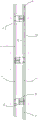
FIG. 1 is a schematic view of an assembled wall with a junction box according to an embodiment of the present invention;
FIG. 2 is a schematic view of an assembled wall according to an embodiment of the present invention;
FIG. 3 is an enlarged view of a portion of FIG. 2;
FIG. 4 is a schematic view of a first wall panel;
FIG. 5 is a schematic view of a second wall panel;
FIG. 6 is a schematic view of a ceiling keel on a floor;
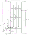
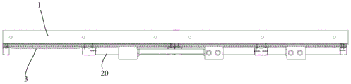
FIG. 7 is a schematic view of the installation of the wiring assembly;
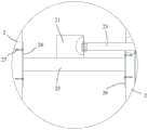
FIG. 8 is an enlarged view of a portion of FIG. 7 at B;
FIG. 9 is an enlarged view of a portion of FIG. 7 at C;
FIG. 10 is a schematic view of a cell wall panel with a junction box assembly;
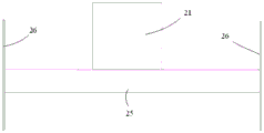
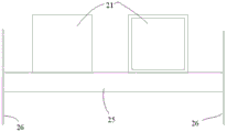
FIG. 11 is a schematic view of the junction box integrated with the cross bracket;
FIG. 12 is a schematic view of a conduit mount;
FIG. 13 is a schematic view of a first wall layer installation;
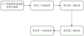
FIG. 14 is a schematic view of a manufacturing method according to an embodiment of the invention;
FIG. 15 is a schematic view of a wiring assembly according to another embodiment of the present invention.
Reference numerals: 1-top and bottom keel, 2-keel assembly, 3-first wall body layer, 4-second wall body layer, 5-first wall plate, 6-second wall plate, 7-first self-tapping nail, 8-second self-tapping nail, 9-third self-tapping nail, 10-first vertical keel, 11-second vertical keel, 12-wall panel, 13-heat insulation layer, 14-expansion screw, 15-floor, 16-unit wall plate, 17-ceiling, 20-junction box assembly, 21-junction box, 22-cross bracket, 23-line pipe, 24-line pipe bracket, 25-cross bracket body, 26-binding plate, 27-fourth self-tapping nail and 28-perforation.
Detailed Description
In order to make the objects, technical solutions and advantages of the present invention more apparent, embodiments of the present invention will be described in detail below with reference to the accompanying drawings. It should be noted that the embodiments and features of the embodiments in the present application may be arbitrarily combined with each other without conflict.
Please refer to fig. 1 to 14, which illustrate an assembled wall with a junction box according to the present invention. The assembled wall body comprises a ceiling keel 1 fixed on a ceiling and a floor respectively, and a partition wall erected between the ceiling and the floor, wherein the partition wall is composed of a first wall body layer 3 and a second wall body layer 4, the first wall body layer 3 and the second wall body layer 4 are parallel, the upper end and the lower end of the first wall body layer 3 and the upper end and the lower end of the second wall body layer 4 are respectively connected with the ceiling keel 1, and the first wall body layer 3 and the second wall body layer 4 are fixed into a whole to form the partition wall, namely the first wall body layer 3 and the second wall body layer 4 are overlapped in the thickness direction of the partition wall. Specifically, the first wall body layer 3 and the second wall body layer 4 are both composed of a plurality of unit wall panels 16 arranged along the length direction thereof, the unit wall panels 16 further include wall panels 12, and heat insulation layers 13 and studs 2 provided on one side thereof, and at least one unit wall panel 16 is provided with a terminal box assembly 20, and the wall panel 12 is provided with a notch (not shown) corresponding to the terminal box assembly 20 for wiring. From this, this assembled wall body is with partition wall in thickness direction share two parts, first wall body layer 3 and second wall body layer 4 promptly, assembles, has avoided the tenon and the mortise structure of current assembled wall body, does not destroy the heat preservation during the installation, and can guarantee the good thermal-insulated sound insulation performance of whole wall body. Meanwhile, the junction box assembly 20 does not need to be installed on site, so that the installation efficiency can be improved, and the labor intensity of construction workers can be reduced.
Specifically, the gaps between the adjacent unit wall panels 16 of the first wall body layer 3 and the gaps between the adjacent unit wall panels 16 of the second wall body layer 4 are staggered, so that the heat preservation and insulation performance can be further improved. The plurality of unit wall panels 16 are divided into a first wall panel 5 and a second wall panel 6 according to their lengths, wherein the first wall panel 5 and the second wall panel 6 have the same height, and the length of the second wall panel 6 is half of the length of the first wall panel 5. Meanwhile, the first wall panel 5 and the second wall panel 6 are both composed of a wall panel 12, an insulation layer 13 and a mullion 2. Therefore, the first wall plate 5 and the second wall plate 6 are arranged in a mixed mode, and gap staggering can be achieved.
As for the first wall panel 5, as shown in fig. 3 and 4, the wall panel 12 of the first wall panel 5 is gypsum board; the heat preservation 14 is laid on shingle nail 12 and is separated vertical keel 2 and shingle nail 12, and the heat preservation 14 bonds one side of covering whole shingle nail 12, and it is cotton for glass, and it also is not limited to glass cotton, also can be rock wool, and the heat preservation 14 is installed between vertical keel 2 and shingle nail 12, has reduced the acoustic bridge and the heat bridge between vertical keel 2 and shingle nail 12, and is of benefit to the thermal-insulated sound insulation that keeps warm. The mullion 2 includes a first mullion 10 vertically disposed at both ends of the first wall panel 5 in the length direction, and a second mullion 11 disposed at the center of the wall panel 12 of the first wall panel 5. Further, the first and second studs 10 and 11 are light steel studs, and have C-shaped cross sections, and an opening is formed at one side thereof. The first and second studs 10 and 11 have the same length and height, but the width of the first stud 10 is half of the width of the second stud 11, the opening of the first stud 10 faces away from the insulation layer 14 adjacent thereto, and the opening of the second stud 11 faces toward the insulation layer 14 adjacent thereto. Meanwhile, the first vertical keel 10 and the second vertical keel 11 are fixed on the wall panel 12 through the third self-tapping screw 9, wherein the third self-tapping screw 9 is driven into the wall panel 12 from one side of the wall panel and penetrates through the wall panel 12 and the heat insulation layer 14, the first vertical keel 10 or the second vertical keel 11 is driven into the wall panel, the heat insulation layer 14 is extruded by the first vertical keel 10 or the second vertical keel 11, and the thickness of the heat insulation layer 14 at the position of the vertical keel 2 is smaller than that of the heat insulation layer 14 at other positions. Notably, first vertical keel 10 sets up at 5 length direction both ends of first wallboard, and protect gypsum board limit portion, can promote gypsum board limit portion intensity, and the transportation of being convenient for reduces the damage of shingle nail limit portion.
In the case of the second wall panel 6, as shown in fig. 3 and 5, the wall panel 12 of the second wall panel 6 is gypsum board, the wall panel 12 of the second wall panel 6 has the same thickness as the wall panel 12 of the first wall panel 5, and the wall panel 12 of the second wall panel 6 has a length which is one-half of the length of the wall panel 12 of the first wall panel 5. The heat preservation 14 is laid on shingle nail 12 and is separated vertical keel 2 and shingle nail 12, and the heat preservation 14 bonds one side of covering whole shingle nail 12, and it is cotton for glass, and it also is not limited to glass cotton, also can be rock wool, and the heat preservation 14 is installed between vertical keel 2 and shingle nail 12, has reduced the acoustic bridge and the heat bridge between vertical keel 2 and shingle nail 12, and is of benefit to the thermal-insulated sound insulation that keeps warm. The vertical keel 2 comprises a first vertical keel 10 vertically arranged at two ends of the first wall plate 5 in the length direction, wherein the first vertical keel 10 and the second vertical keel 11 are light steel keels, the cross sections of the first vertical keel 10 and the second vertical keel 11 are C-shaped, openings are formed in one sides of the first vertical keel 10 and the second vertical keel 11, and the first vertical keel 10 and the second vertical keel 11 can also be rectangular fully-closed keels. The first vertical keel 10 has the same size, shape and length as the first vertical keel 10 of the first wall panel 5, and the opening of the first vertical keel 10 faces away from the heat insulation layer 14 tightly attached to the first vertical keel. Meanwhile, the first stud 10 is fixed on the wall panel 12 through a third self-tapping screw 9, wherein the third self-tapping screw 9 is driven into and penetrates through the wall panel 12 and the heat insulation layer 14 from one side of the wall panel 12, the first stud 10 is driven into the first stud 10, and the heat insulation layer 14 is extruded by the first stud 10, so that the thickness of the heat insulation layer 14 at the vertical keel 2 is smaller than that of the heat insulation layers 14 at other positions.
In addition, the vertical keel 2 on the first wall body layer 3 corresponds the counterbalance with the vertical keel 2 on the second wall body layer 4, and the shingle nail on the first wall body layer 3 and the shingle nail on the second wall body layer 4 are in both sides, as the wall, simultaneously, first wall body layer 3 and second wall body layer 4 are fixed through first self-tapping screw 7, first self-tapping screw 7 runs through first wall body layer 3 or second wall body layer 4 to the vertical keel 2 of relative unit wallboard 16 is squeezed into, guarantee that the wall wholly has very high intensity. Also, the junction box assembly 20 may be installed regardless of the first wall panel 5 or the second wall panel 6, and thus, the unit wall panels 16 may be divided into two types according to whether the junction box assembly 20 is provided or not, i.e., the unit wall panel 16 with the junction box assembly and the unit wall panel 16 without the junction box assembly. Taking the first wall plate 5 with the junction box assembly as an example, as shown in fig. 10, the first wall plate 5 is provided with three vertical keels 2, two gaps are formed between the three vertical keels 2, a junction box assembly 20 is installed in each gap, and the first wall plate 5 is provided with a notch (not shown) corresponding to all the junction box assemblies 20.
As shown in fig. 1, 2 and 6, the ceiling keel 1 is L-shaped, or may be U-shaped, wherein two L-shaped ceiling keels may be disposed on the ceiling 17 or the floor 15, and the L-shaped ceiling keels 1 on the ceiling 17 and the floor 15 are fixed to the unit wall panels 16 in the same manner. Taking the floor 15 as an example, two L-shaped top and bottom keels 1 are respectively fixed with the floor 15 through expansion screws 14, the two L-shaped top and bottom keels 1 are arranged in parallel and along the length direction of the partition wall, the two L-shaped top and bottom keels 1 form a 'er' shape, and an installation space of the partition wall is formed between the two L-shaped top and bottom keels 1. The top and bottom keel 1 is fixed with the unit wall board 16 through a second self-tapping screw 8, and the second self-tapping screw 8 is driven into the outer side of the L-shaped top and bottom keel 1, penetrates through the wall panel 12 and the heat insulation layer 13 and is driven into the vertical keel 2. In addition, the upper and lower ends of the partition wall are not provided with transverse keels, a keel frame is not formed by the transverse keels and the vertical keels 2, and the partition wall can be connected with the ceiling 17 or the floor 15 only through the L-shaped ceiling keel 1.
As shown in fig. 1, 7, 8 and 11, the junction box assembly 20 includes a junction box 21, a cross bracket 22 and a conduit 23, wherein the junction box 21 is fixed on the cross bracket 22, the conduit is led out from the junction box 23, the cross bracket 22 is fixed on the vertical keel 2 of the first wall body 3, and the first wall body 3 is provided with a notch (not shown) corresponding to the junction box 21, so that the junction box 21 is exposed out of the wall panel 12 for connection. The transverse support 22 is fixed between the two vertical keels 2 and comprises a horizontal transverse support body 25 and attachment plates 26 arranged at two ends of the transverse support body 25, the transverse support body 25 is perpendicular to the attachment plates 26, the transverse support body 25 is a U-shaped keel, but is not limited to a U-shaped keel, and can also be a C-shaped keel, an L-shaped keel or a square tube; the attachment plate 26 abuts against the stud and is fixed by a fourth self-tapping screw 27. The conduits 23 connecting the junction boxes 21 may be arranged horizontally or vertically, and a plurality of conduits 23 may be connected to a single junction box 21 according to the number of cables. As shown in fig. 9 and 12, in order to keep the conduit 23 vertical, a horizontal conduit bracket 24 is provided between the two vertical keels 2 on the unit wall panel provided with the junction box assembly, and is of the same structure as the transverse bracket 22 and is composed of a transverse bracket body 25 and an abutting plate 26, and the main difference is that a through hole 28 is provided on the transverse bracket body 25, so that the conduit 23 can pass through the conduit bracket to support the conduit 23 and keep the conduit 23 in a straight line arrangement.
In the formation of the assembled wall, as shown in fig. 14, first, the first wall panel 5 and the second wall panel 6 are manufactured and assembled in a factory, and a plurality of first wall panels 5 or second wall panels 6 are fixed with a junction box assembly, and then transported to an installation site. Subsequently, according to the preset position, the ceiling 17 and the floor 15 are respectively fixed with the ground keel 1, when the installation is carried out, the horizontal and vertical laser instrument is used for marking the line on the ceiling and the floor, and the ink line is used for popping up the mark, so that the ground keel 1 can be fixed corresponding to the mark. Then, the installation of the first wall body layer 3 is completed, that is, the unit wall panels 16 of the first wall body layer 3 are sequentially fixed on the ceiling keel 1. Finally, the installation of the second wall body layer 4 is completed, the unit wall boards 16 of the second wall body layer 4 are fixed on the first wall body layer 3 one by one, and then another ceiling keel 1 is installed, thereby realizing the installation of the whole assembly type wall body.
In addition, when the assembled wall body is formed, the unit wall boards 16 of the first wall body layer 3 and the unit wall boards 16 of the second wall body layer 4 can be alternately installed, and the second wall body layer 4 does not need to be installed after the first wall body layer 3 is installed.
In another embodiment, as shown in fig. 15, two junction boxes 21 are fixed on the cross bracket 22, and the two junction boxes 21 have different opening directions, i.e. one faces the first wall body layer 3 and the other faces the second wall body layer 4, when the junction boxes 21 are installed, the first wall body layer 3 and the second wall body layer 4 need to be notched corresponding to the different junction boxes 21, so that the junction boxes 21 are exposed out of the wall body.
By combining the embodiment, the junction box assembly of the assembled wall body does not need to be installed on site, the installation efficiency is improved, and the labor intensity of construction workers is reduced. The partition wall provided by the embodiment of the invention is divided into two parts in the thickness direction, namely the first wall body layer and the second wall body layer, so that the weight of the unit wall board forming the first wall body layer and the second wall body layer is greatly reduced compared with that of the existing assembly type wall body module, the labor intensity during manual carrying and installation is greatly reduced, and the installation is more convenient.
In the description of the present invention, it should be noted that the terms "upper", "lower", "one side", "the other side", "one end", "the other end", "side", "opposite", "four corners", "periphery", "mouth" structure ", and the like indicate orientations or positional relationships based on those shown in the drawings, and are only for convenience of describing the present invention and simplifying the description, but do not indicate or imply that the structures referred to have specific orientations, are configured and operated in specific orientations, and thus, are not to be construed as limiting the present invention.
In the description of the embodiments of the present invention, unless otherwise explicitly specified or limited, the terms "connected," "directly connected," "indirectly connected," "fixedly connected," "mounted," and "assembled" are to be construed broadly and may, for example, be fixedly connected, detachably connected, or integrally connected; the terms "mounted," "connected," and "fixedly connected" may be directly connected or indirectly connected through intervening media, or may be connected through two elements. The specific meanings of the above terms in the present invention can be understood in specific cases to those skilled in the art.
Although the embodiments of the present invention have been described above, the above description is only for the convenience of understanding the present invention, and is not intended to limit the present invention. It will be understood by those skilled in the art that various changes in form and details may be made therein without departing from the spirit and scope of the invention as defined by the appended claims.
Claims (10)
1. The assembled wall body with the junction box comprises a ceiling keel fixed on a floor and a ceiling, and is characterized by comprising a first wall body layer and a second wall body layer, wherein the first wall body layer and the second wall body layer are overlapped in the thickness direction of the assembled wall body to form a partition wall, and the upper end and the lower end of the partition wall are respectively fixed with the ceiling keel;
the first wall body layer and the second wall body layer are both composed of a plurality of unit wall boards which are arranged along the length direction of the first wall body layer and the second wall body layer, each unit wall board comprises a wall panel, and a heat insulation layer and a vertical keel which are arranged on one side of the wall panel, and the heat insulation layer is laid on the wall panel and separates the vertical keel and the wall panel;
the unit wall plate is set to be a first wall plate or a second wall plate, and the length of the second wall plate is smaller than that of the first wall plate;
at least one be provided with the terminal box subassembly on the unit wallboard, the shingle nail corresponds the terminal box subassembly is equipped with the breach.
2. The assembly wall with junction box of claim 1, wherein the junction box assembly comprises a junction box, a cross bracket and a conduit, the junction box is fixed on the cross bracket, the conduit is led out from the junction box, and the cross bracket is fixed between the two vertical keels.
3. The assembly type wall with the junction box as claimed in claim 2, wherein the cross bracket comprises a horizontal cross bracket body and abutting plates arranged at two ends of the cross bracket body, and the abutting plates abut against and are fixed to the vertical keels.
4. An assembled wall with a junction box as claimed in claim 3, wherein at least one of said unit wall panels is provided with a conduit bracket, said conduit bracket is fixed between two of said vertical keels, and said conduit passes through said conduit bracket for supporting said conduit.
5. The assembly-type wall with the junction box as claimed in claim 3, wherein the cross bracket main body is a U-shaped keel, a C-shaped keel, an L-shaped keel or a square tube.
6. The assembly wall with junction box of claim 2, wherein said cross bracket has a plurality of junction boxes, and openings of said plurality of junction boxes are arranged in a same direction or in a back direction.
7. The assembled wall with junction box of any of claims 1-6, wherein the gaps between adjacent unit wall panels of the first wall body course are staggered from the gaps between adjacent unit wall panels of the second wall body course.
8. A method of manufacturing an assembled wall with a junction box according to any one of claims 1 to 7, comprising:
(1) preparing a plurality of unit wall boards in a factory, fixing a junction box assembly on at least one unit wall board, and transporting the unit wall boards to a construction site after the completion;
(2) fixing a ceiling keel and a floor keel on the ceiling and the floor respectively, wherein the ceiling keel is arranged along the length direction of the assembled wall body;
(3) and installing each unit wallboard to form a partition wall.
9. The method of manufacturing an assembled wall with a junction box as set forth in claim 8, wherein in the step (1), a notch is preformed in at least one of the wall panels, and the junction box assembly is fixed in correspondence with the notch.
10. The method for manufacturing an assembled wall with junction box as claimed in claim 8, wherein in step (3), the unit wall panels of the first wall layer are fixed on the ceiling keel, and then the second wall layer is fixed on the first wall layer; or the unit wall boards of the first wall body layer and the unit wall boards of the second wall body layer are alternately installed.
Priority Applications (1)
| Application Number | Priority Date | Filing Date | Title |
|---|---|---|---|
| CN202011618037.2A CN112942633A (en) | 2020-12-31 | 2020-12-31 | Assembled wall with junction box and manufacturing method thereof |
Applications Claiming Priority (1)
| Application Number | Priority Date | Filing Date | Title |
|---|---|---|---|
| CN202011618037.2A CN112942633A (en) | 2020-12-31 | 2020-12-31 | Assembled wall with junction box and manufacturing method thereof |
Publications (1)
| Publication Number | Publication Date |
|---|---|
| CN112942633A true CN112942633A (en) | 2021-06-11 |
Family
ID=76235386
Family Applications (1)
| Application Number | Title | Priority Date | Filing Date |
|---|---|---|---|
| CN202011618037.2A Pending CN112942633A (en) | 2020-12-31 | 2020-12-31 | Assembled wall with junction box and manufacturing method thereof |
Country Status (1)
| Country | Link |
|---|---|
| CN (1) | CN112942633A (en) |
Cited By (2)
| Publication number | Priority date | Publication date | Assignee | Title |
|---|---|---|---|---|
| CN113594989A (en) * | 2021-06-29 | 2021-11-02 | 北新集团建材股份有限公司 | Quick mounting structure of terminal box |
| CN115030370A (en) * | 2022-06-30 | 2022-09-09 | 北新集团建材股份有限公司 | Wall with wiring bottom box and construction method |
Citations (7)
| Publication number | Priority date | Publication date | Assignee | Title |
|---|---|---|---|---|
| CN206174422U (en) * | 2016-10-26 | 2017-05-17 | 中冶建工集团有限公司 | A fixed knot constructs for inciting somebody to action on line box is fixed in light gypsum board partition wall |
| CN206585293U (en) * | 2017-01-18 | 2017-10-24 | 山东飞越钢结构工程有限公司 | A kind of terminal box fixing device |
| CN108301539A (en) * | 2018-03-16 | 2018-07-20 | 广东省建筑装饰工程有限公司 | Unit assembled integration facing light steel keel partition structure and its construction method |
| CN110469048A (en) * | 2019-07-30 | 2019-11-19 | 北新集团建材股份有限公司 | A kind of wiring method of assembled wall |
| CN110872879A (en) * | 2018-08-30 | 2020-03-10 | 北新集团建材股份有限公司 | Modular wall |
| CN110872875A (en) * | 2018-08-30 | 2020-03-10 | 北新集团建材股份有限公司 | Assembled wall and mounting method |
| CN211774823U (en) * | 2019-10-21 | 2020-10-27 | 绿城装饰工程集团有限公司 | Assembled light partition wall |
-
2020
- 2020-12-31 CN CN202011618037.2A patent/CN112942633A/en active Pending
Patent Citations (7)
| Publication number | Priority date | Publication date | Assignee | Title |
|---|---|---|---|---|
| CN206174422U (en) * | 2016-10-26 | 2017-05-17 | 中冶建工集团有限公司 | A fixed knot constructs for inciting somebody to action on line box is fixed in light gypsum board partition wall |
| CN206585293U (en) * | 2017-01-18 | 2017-10-24 | 山东飞越钢结构工程有限公司 | A kind of terminal box fixing device |
| CN108301539A (en) * | 2018-03-16 | 2018-07-20 | 广东省建筑装饰工程有限公司 | Unit assembled integration facing light steel keel partition structure and its construction method |
| CN110872879A (en) * | 2018-08-30 | 2020-03-10 | 北新集团建材股份有限公司 | Modular wall |
| CN110872875A (en) * | 2018-08-30 | 2020-03-10 | 北新集团建材股份有限公司 | Assembled wall and mounting method |
| CN110469048A (en) * | 2019-07-30 | 2019-11-19 | 北新集团建材股份有限公司 | A kind of wiring method of assembled wall |
| CN211774823U (en) * | 2019-10-21 | 2020-10-27 | 绿城装饰工程集团有限公司 | Assembled light partition wall |
Non-Patent Citations (2)
| Title |
|---|
| 王鹏起等: "装配式内隔墙系统探讨", 《新型建筑材料》 * |
| 贺剑平等: "《室内建筑装饰构造与工艺》", 31 January 2016 * |
Cited By (2)
| Publication number | Priority date | Publication date | Assignee | Title |
|---|---|---|---|---|
| CN113594989A (en) * | 2021-06-29 | 2021-11-02 | 北新集团建材股份有限公司 | Quick mounting structure of terminal box |
| CN115030370A (en) * | 2022-06-30 | 2022-09-09 | 北新集团建材股份有限公司 | Wall with wiring bottom box and construction method |
Similar Documents
| Publication | Publication Date | Title |
|---|---|---|
| CN110469049B (en) | Building wall and installation method thereof | |
| CN112942633A (en) | Assembled wall with junction box and manufacturing method thereof | |
| CN112814211B (en) | Mounting method of assembled wall | |
| WO2021227450A1 (en) | Modular factory building | |
| CN112814213A (en) | Assembly type wall with wire box and installation method thereof | |
| CN111424854B (en) | Keel pipeline module assembled with cement lath | |
| CN218522129U (en) | Well wall | |
| CN112814212A (en) | Mounting method of assembled wall | |
| CN116815956A (en) | Assembled wall with window and installation method thereof | |
| CN113605549A (en) | Multi-cavity wall structure | |
| CN113700164A (en) | Support keel suitable for multi-cavity wall and mounting structure | |
| CN212405594U (en) | Wall module and assembled wall | |
| CN212001696U (en) | Sound insulation type light steel keel partition wall | |
| CN218149084U (en) | Green building and assembled partition wall | |
| CN112832418A (en) | Assembled wall body system | |
| CN221399986U (en) | Light steel sandwich board fast-assembling room of titanium magnesium fire-proof board | |
| CN219261432U (en) | Modular mortise and tenon partition wall | |
| CN218091455U (en) | Modularization wall body pipeline assembly structure | |
| CN115450397B (en) | Hoistway wall and installation method thereof | |
| CN219604577U (en) | Photovoltaic heat preservation integrated plate and photovoltaic heat preservation system | |
| CN221001526U (en) | Light steel joist wall system with limiting groove | |
| CN112814220B (en) | Assembly type wall body structure with square tube air duct and installation method | |
| CN217326672U (en) | Split corridor module | |
| CN213773815U (en) | Assembled house structure system based on composite heat-insulation wallboard | |
| CN217537409U (en) | Composite wall structure for modular substation |
Legal Events
| Date | Code | Title | Description |
|---|---|---|---|
| PB01 | Publication | ||
| PB01 | Publication | ||
| SE01 | Entry into force of request for substantive examination | ||
| SE01 | Entry into force of request for substantive examination | ||
| RJ01 | Rejection of invention patent application after publication | ||
| RJ01 | Rejection of invention patent application after publication |
Application publication date: 20210611 |