CN112937227A - Automatic assembling machine for solid tire of electric bicycle - Google Patents
Automatic assembling machine for solid tire of electric bicycle Download PDFInfo
- Publication number
- CN112937227A CN112937227A CN202110352420.6A CN202110352420A CN112937227A CN 112937227 A CN112937227 A CN 112937227A CN 202110352420 A CN202110352420 A CN 202110352420A CN 112937227 A CN112937227 A CN 112937227A
- Authority
- CN
- China
- Prior art keywords
- tire
- driving
- plate
- lifting
- positioning
- Prior art date
- Legal status (The legal status is an assumption and is not a legal conclusion. Google has not performed a legal analysis and makes no representation as to the accuracy of the status listed.)
- Pending
Links
Images


Classifications
-
- B—PERFORMING OPERATIONS; TRANSPORTING
- B60—VEHICLES IN GENERAL
- B60C—VEHICLE TYRES; TYRE INFLATION; TYRE CHANGING; CONNECTING VALVES TO INFLATABLE ELASTIC BODIES IN GENERAL; DEVICES OR ARRANGEMENTS RELATED TO TYRES
- B60C25/00—Apparatus or tools adapted for mounting, removing or inspecting tyres
- B60C25/01—Apparatus or tools adapted for mounting, removing or inspecting tyres for removing tyres from or mounting tyres on wheels
- B60C25/05—Machines
- B60C25/0503—Machines for mounting only
-
- B—PERFORMING OPERATIONS; TRANSPORTING
- B60—VEHICLES IN GENERAL
- B60C—VEHICLE TYRES; TYRE INFLATION; TYRE CHANGING; CONNECTING VALVES TO INFLATABLE ELASTIC BODIES IN GENERAL; DEVICES OR ARRANGEMENTS RELATED TO TYRES
- B60C25/00—Apparatus or tools adapted for mounting, removing or inspecting tyres
- B60C25/01—Apparatus or tools adapted for mounting, removing or inspecting tyres for removing tyres from or mounting tyres on wheels
- B60C25/05—Machines
- B60C25/0521—Handling of rim or tyre, e.g. lifting and positioning devices
-
- B—PERFORMING OPERATIONS; TRANSPORTING
- B60—VEHICLES IN GENERAL
- B60C—VEHICLE TYRES; TYRE INFLATION; TYRE CHANGING; CONNECTING VALVES TO INFLATABLE ELASTIC BODIES IN GENERAL; DEVICES OR ARRANGEMENTS RELATED TO TYRES
- B60C25/00—Apparatus or tools adapted for mounting, removing or inspecting tyres
- B60C25/01—Apparatus or tools adapted for mounting, removing or inspecting tyres for removing tyres from or mounting tyres on wheels
- B60C25/05—Machines
- B60C25/053—Support of wheel parts during machine operation
- B60C25/0539—Support of wheel parts during machine operation radially fixing the rim, e.g. with gripping claws
-
- B—PERFORMING OPERATIONS; TRANSPORTING
- B60—VEHICLES IN GENERAL
- B60C—VEHICLE TYRES; TYRE INFLATION; TYRE CHANGING; CONNECTING VALVES TO INFLATABLE ELASTIC BODIES IN GENERAL; DEVICES OR ARRANGEMENTS RELATED TO TYRES
- B60C25/00—Apparatus or tools adapted for mounting, removing or inspecting tyres
- B60C25/01—Apparatus or tools adapted for mounting, removing or inspecting tyres for removing tyres from or mounting tyres on wheels
- B60C25/05—Machines
- B60C25/053—Support of wheel parts during machine operation
- B60C25/0542—Support of wheel parts during machine operation with self-centering means, e.g. cones
-
- B—PERFORMING OPERATIONS; TRANSPORTING
- B60—VEHICLES IN GENERAL
- B60C—VEHICLE TYRES; TYRE INFLATION; TYRE CHANGING; CONNECTING VALVES TO INFLATABLE ELASTIC BODIES IN GENERAL; DEVICES OR ARRANGEMENTS RELATED TO TYRES
- B60C25/00—Apparatus or tools adapted for mounting, removing or inspecting tyres
- B60C25/01—Apparatus or tools adapted for mounting, removing or inspecting tyres for removing tyres from or mounting tyres on wheels
- B60C25/05—Machines
- B60C25/0548—Machines equipped with sensing means, e.g. for positioning, measuring or controlling
-
- B—PERFORMING OPERATIONS; TRANSPORTING
- B60—VEHICLES IN GENERAL
- B60C—VEHICLE TYRES; TYRE INFLATION; TYRE CHANGING; CONNECTING VALVES TO INFLATABLE ELASTIC BODIES IN GENERAL; DEVICES OR ARRANGEMENTS RELATED TO TYRES
- B60C2200/00—Tyres specially adapted for particular applications
- B60C2200/12—Tyres specially adapted for particular applications for bicycles
Landscapes
- Engineering & Computer Science (AREA)
- Mechanical Engineering (AREA)
- Tyre Moulding (AREA)
Abstract
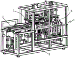
The invention relates to an automatic assembling machine for solid tires of an electric bicycle, which comprises a rack, wherein a linear conveying line is arranged on the rack, a tire installing mechanism is also arranged on the rack, and the tire installing mechanism comprises a positioning and lifting mechanism and a tire supporting mechanism positioned right above the positioning and lifting mechanism; the linear conveying line passes through the positioning and lifting mechanism; according to the invention, the expander is adopted to expand the inner ring of the solid tire, and then the solid tire is sleeved on the wheel hub, so that the problem of low efficiency of the existing extrusion mode for assembling the vacuum wheel is solved, the assembly speed of the solid lift is greatly improved, and the invention has the characteristics of reasonable structure and high efficiency.
Description
Technical Field
The invention relates to tire assembly equipment, in particular to an automatic assembly machine for solid tires of electric bicycles.
Background
The shared bicycle usually adopts solid tires in order to avoid tire puncture, the conventional automatic tire assembling machine mainly aims at vacuum wheels, and the conventional automatic extrusion tire assembling machine is small in extrusion deformation quantity of the side parts of the solid tires, cannot automatically complete the assembling work of the solid tires and needs workers to assist or assist other tools, so that the conventional solid tire assembling effect is poor, the assembling speed is low, and the production efficiency is limited.
Disclosure of Invention
The invention aims to provide an automatic assembling machine for solid tires of electric bicycles, which adopts an expander to expand the inner ring of the solid tire and then sleeves the solid tire on a wheel hub.
The following technical scheme is adopted for achieving the purpose:
the utility model provides an electric bicycle solid tyre automatic assembly machine, includes the frame, is provided with the straight line transmission line in the frame, its characterized in that: the tire installing mechanism comprises a positioning and lifting mechanism and a tire supporting mechanism positioned right above the positioning and lifting mechanism; the linear conveying line passes through the positioning and lifting mechanism.
The positioning and lifting mechanism 2 comprises a positioning mechanism 22 and a lifting mechanism 21, the lifting mechanism 21 is arranged on the frame 1, the lifting mechanism 21 comprises a lifting platform 211 and a platform lifting driving mechanism 212, the platform lifting driving mechanism 212 drives the lifting platform 211 to ascend or descend, and a channel 213 for a linear transmission line to pass through is arranged on the lifting platform 211; the positioning mechanism 22 is arranged at the bottom of the channel; the linear conveyor line 11 passes through the passage 213.
The positioning mechanism 22 comprises a bottom plate 221 and a lifting plate 222 above the bottom plate, the bottom plate 221 is connected with the lifting plate 222 through a positioning lifting cylinder 223, two groups of positioning columns 224 are arranged on the upper surface of the lifting plate 222 through a guide mechanism, the direction of the guide mechanism is the same as that of a linear transmission line, a positioning gear 225 is arranged in the middle of the upper surface of the lifting plate 222, the two groups of positioning columns 224 are distributed on two sides of the linear transmission line of the positioning gear 225, the two groups of positioning columns 224 are meshed with the positioning gear 225 through racks 226 of the guide mechanism, the two linear racks 226 are distributed on two sides of the positioning gear 225, and the positioning gear 225 is driven by a motor.
The tire supporting mechanism comprises a support, a rotating motor, a tire supporting lifting cylinder, a separating plate, a guide plate, a driving plate and a plurality of tire supporting rods, wherein the support is fixedly connected with a rack, the tire supporting lifting cylinder is fixed on the support, a connecting seat is arranged below the support, the driving plate is rotatably sleeved on the connecting seat, the guide plate is fixedly connected with the connecting seat and arranged below the driving plate in parallel, a plurality of guide grooves which vertically penetrate through the guide plate are arranged on the guide plate along the radial direction by taking the central axis of the driving plate as an axis, a plurality of driving grooves which vertically penetrate through the driving plate are arranged on the driving plate corresponding to the guide grooves, the tire supporting rods are arranged between the guide plate and the driving plate, the tire supporting rods are connected with the guide plate through radial guide mechanisms, a driving part at the tops of the tire supporting rods is accommodated in the driving grooves, supporting rods at the lower parts of, the driving groove and the guide groove are matched to drive the plurality of tire supporting rods to expand or contract along the direction of the guide groove; a separation plate is arranged below the guide plate, and a notch for the stay bar to move in the radial direction is formed in the separation plate; the tire supporting lifting cylinder drives the guide plate and the separating plate to be separated from each other up and down.
The driving plate is sleeved on the connecting seat through a bearing, the connecting seat is fixedly connected with the bracket, and the driving rod of the tire supporting lifting cylinder is connected with the separating plate; the separation plate is matched with the guide post sleeve on the bracket through the guide post.
The rotating motor is fixed on the bracket through a connecting plate; an arc-shaped rack is arranged on the top surface of the driving plate close to the connecting edge and meshed with a driving gear of an output shaft of the rotating motor; the rotating motor drives the driving plate to rotate through the meshing of the driving gear and the arc-shaped rack.
The radial guide mechanism comprises radial guide rails distributed on two sides of the radial guide groove, a tire supporting rod is fixedly connected with a sliding block on the radial guide rails, a driving part on the upper portion of the tire supporting rod is provided with a driving bearing, and the outer diameter of the driving bearing is matched with the width of the driving groove.
The projection of the driving groove on the guide plate along the axial direction forms an included angle of 30-60 degrees with the guide groove.
The driving groove is linear or arc.
The machine frame is also provided with a tire finishing mechanism, and the tire finishing mechanism comprises a rotary driving mechanism and a tire pressing and shaping mechanism; the linear conveying line passes through the interior of the rotary driving mechanism; the tire pressing and shaping mechanism comprises an upper tire pressing mechanism and a lower tire pressing mechanism, and the upper tire pressing mechanism and the lower tire pressing mechanism are distributed above and below the linear conveying line.
The rotary driving mechanism comprises two groups of friction driving columns distributed on two sides of the linear transmission line, each group of friction driving columns is pivoted on a respective friction support, the two groups of friction supports are symmetrically distributed on two sides of the linear transmission line, a linkage mechanism is arranged between the two groups of friction supports, and the linkage mechanism drives the friction supports to be close to or far away from the linear transmission line synchronously.
The linkage mechanism comprises a linkage arm, a connecting rod and a linkage cylinder, wherein the cylinder body of the linkage cylinder is pivoted on the rack, the driving rod of the linkage cylinder is connected with the friction support on one side, the middle part of the linkage arm is pivoted on the rack, and the two ends of the linkage arm are respectively movably connected with the friction supports on the two sides through the connecting rod.
Each group of friction driving columns comprises a driving column and a driven friction column which are arranged in parallel, and the driving columns are driven by a driving motor.
The middle parts of the driving column and the driven friction column are provided with annular grooves, and the side walls of the annular grooves are of inclined planes or cambered surface structures.
Go up and press child mechanism down and all include the tire pressing wheel group, adjust the seat and press child elevating system, the regulation seat include regulating plate, accommodate the lead screw and screw seat, accommodate the lead screw is provided with on the screw seat through the bearing, the accommodate the lead screw direction is parallel with straight line transmission line direction, be equipped with the screw thread section of two sections direction looks boards on the accommodate the lead screw, two sections screw thread section symmetric distribution are at accommodate the lead screw's both ends, all connect screw-nut soon on two sections screw thread sections, be provided with the guide rail in one side or both sides of accommodate the lead screw, the tire pressing wheel group links firmly with the slider on the guide rail, the tire pressing wheel group still links firmly with.
The tire pressing wheel group comprises a tire pressing seat and two pressing wheels, the tire pressing seat is provided with a protruding part, the end part of the protruding part is fixed with the tire pressing seat, the tire pressing seat is provided with a wheel pressing shaft, and the two pressing wheels are pivoted on the wheel pressing shaft.
The invention aims at the installation mode that the solid tire adopts the tire expanding assembly, the positions of the tire and the wheel hub are fixed by a positioning mechanism during the assembly, the characteristic of high strength of the solid tire is utilized, the inner ring of the solid tire is expanded by a tire supporting mechanism, then the wheel hub can be easily placed in the inner ring of the solid tire, then the solid tire and the wheel hub are fixed on the same plane from the upper side and the lower side by a tire supporting mechanism separating plate and a lifting platform of the positioning mechanism, and simultaneously a tire supporting rod is pulled out to enable the solid tire to retract and tighten the wheel hub to complete the assembly work.
Drawings
FIG. 1 is a schematic structural view of the present invention;
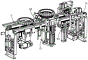
FIG. 2 is a side view of the present invention;
FIG. 3 is a schematic view of a linear conveyor line according to the present invention;
FIG. 4 is a schematic view of a linear conveyor line and a portion of the components of the present invention;
FIG. 5 is a schematic structural view of the positioning and lifting mechanism of the present invention;
FIG. 6 is a schematic diagram of the lifting mechanism of the present invention;
FIG. 7 is a schematic structural view of a positioning mechanism of the present invention;
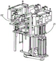
FIG. 8 is a structural schematic view (one) of the tire supporting mechanism of the present invention;
FIG. 9 is a structural schematic view of the tire supporting mechanism of the present invention (II);
FIG. 10 is a bottom view of the tire support mechanism of the present invention;
FIG. 11 is a cross-sectional view taken along line C-C of FIG. 10 in accordance with the present invention;
FIG. 12 is a cross-sectional view taken along line D-D of FIG. 10 in accordance with the present invention;
FIG. 13 is a schematic structural view of the components of the tire support mechanism portion of the present invention;
FIG. 14 is a schematic structural view (one) of a tire retreading mechanism in accordance with the present invention;
FIG. 15 is a schematic structural view of the tire retreading mechanism of the present invention;
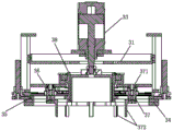
FIG. 16 is a schematic structural view (III) of the tire retreading mechanism of the present invention;
FIG. 17 is a schematic view of the rotary drive mechanism of the present invention;
fig. 18 is a schematic structural view of the tire press shaping mechanism of the present invention.
Detailed Description
As shown in fig. 1-18, an automatic assembling machine for solid tyres of electric bicycles comprises a frame 1, wherein a linear conveyor line 11 is arranged on the frame 1, and is characterized in that: the tire installing mechanism is arranged on the rack 1 and comprises a positioning and lifting mechanism 2 and a tire supporting mechanism 3 positioned right above the positioning and lifting mechanism 2; the straight line conveying line 11 passes through the positioning and lifting mechanism 2.
The positioning and lifting mechanism 2 comprises a positioning mechanism 22 and a lifting mechanism 21, the lifting mechanism 21 is arranged on the frame 1, the lifting mechanism 21 comprises a lifting platform 211 and a platform lifting driving mechanism 212, the platform lifting driving mechanism 212 drives the lifting platform 211 to ascend or descend, and a channel 213 for a linear transmission line to pass through is arranged on the lifting platform 211; the positioning mechanism 22 is arranged at the bottom of the channel; the linear conveyor line 11 passes through the passage 213.
The positioning mechanism 22 comprises a bottom plate 221 and a lifting plate 222 above the bottom plate, the bottom plate 221 is connected with the lifting plate 222 through a positioning lifting cylinder 223, two groups of positioning columns 224 are arranged on the upper surface of the lifting plate 222 through a guide mechanism, the direction of the guide mechanism is the same as the direction of a linear transmission line, a positioning gear 225 is arranged in the middle of the upper surface of the lifting plate 222, the two groups of positioning columns 224 are distributed on two sides of the linear transmission line of the positioning gear 225, the two groups of positioning columns 224 are meshed with the positioning gear 225 through a linear rack 226 of the guide mechanism, and the positioning gear 225 is driven by a motor; the bottom plate 221 of the positioning mechanism 22 is fixed to the bottom of the channel 213.
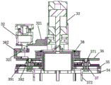
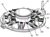
The tire supporting mechanism 3 comprises a support 31, a rotating motor 32, a tire supporting lifting cylinder 33, a separating plate 34, a guide plate 35, a drive plate 36 and a plurality of tire supporting rods 37, the support 31 is fixedly connected with the rack 1, the tire supporting lifting cylinder 32 is fixed on the support 31, a connecting seat 38 is arranged below the support 31, the drive plate 36 is rotatably sleeved on the connecting seat 38, the guide plate 35 is fixedly connected with the connecting seat 38 and is arranged below the drive plate 36 in parallel, a plurality of guide grooves 351 vertically penetrating through the guide plate are arranged on the guide plate 35 along the radial direction by taking the central axis of the drive plate 36 as an axis, a plurality of drive grooves 361 vertically penetrating through the drive plate are arranged on the drive plate 36 corresponding to the guide grooves 351, the tire supporting rods 37 are arranged between the guide plate 35 and the drive plate 36, the tire supporting rods 37 are connected with the guide plate 35 through radial guide mechanisms 39, and drive parts at the tops of the tire supporting rods 37 are accommodated, the support rods 372 at the lower parts of the tire supporting rods 37 downwards penetrate through the guide grooves 351, and the rotary motor 32 drives the driving plate 36 to rotate to drive the plurality of tire supporting rods 37 to expand or contract along the direction of the guide grooves 351 through the matching of the driving grooves 361 and the guide grooves 351; a separation plate 34 is arranged below the guide plate 35, and a notch 341 for the lower part of the stay bar 372 to move in the radial direction is formed in the separation plate 34; the tire supporting lifting cylinder 33 drives the guide plate 35 and the separating plate 34 to be separated up and down.
The driving plate 36 is sleeved on the connecting seat 38 through a bearing, the connecting seat 38 is fixedly connected with the bracket 31, and the driving rod of the tire supporting lifting cylinder 33 is connected with the separating plate 34; the separator plate 34 is fitted to the guide post housing on the bracket 31 by means of the guide post 40.
The rotating motor 32 is fixed on the bracket 31 through a connecting plate 321; an arc-shaped rack 362 is arranged on the top surface of the driving plate 36 close to the connecting edge, and the arc-shaped rack 362 is meshed with the driving gear 321 of the output shaft of the rotating motor 32; the rotary motor 32 drives the driving plate 36 to rotate by engaging the driving gear 321 with the arc-shaped rack 362.
The radial guide mechanism 39 comprises radial guide rails 391 distributed on two sides of the radial guide groove 351, the tire support rod 37 is fixedly connected with a slide block 392 on the radial guide rail 391, a drive part on the upper part of the tire support rod 37 is provided with a drive bearing 371, and the outer diameter of the drive bearing 371 is matched with the width of the drive groove 361.
The projection of the driving groove 361 on the guide plate 35 along the axial direction forms an included angle of 30-60 degrees with the guide groove 351.
The driving groove 361 is linear or arc.
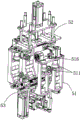
The frame 1 is also provided with a tire finishing mechanism 5, and the tire finishing mechanism 5 comprises a rotary driving mechanism 51 and a tire pressing and shaping mechanism; the linear conveyor line 11 passes through the rotary driving mechanism 51; the tire pressing and shaping mechanism comprises an upper tire pressing mechanism 52 and a lower tire pressing mechanism 53, wherein the upper tire pressing mechanism 52 and the lower tire pressing mechanism 53 are distributed above and below the linear conveying line 11.
The rotary driving mechanism 51 comprises two groups of friction driving columns 511 distributed on two sides of the linear transmission line 11, each group of friction driving columns 511 is pivoted on a respective friction support 512, the two groups of friction supports 512 are symmetrically distributed on two sides of the linear transmission line 11, a linkage mechanism is arranged between the two groups of friction supports 512, and the linkage mechanism drives the friction supports 512 to synchronously approach or keep away from the linear transmission line 11.
The linkage mechanism comprises a linkage arm 513, a connecting rod 514 and a linkage air cylinder 515, wherein a cylinder body of the linkage air cylinder 515 is pivoted on the rack 1, a driving rod of the linkage air cylinder 515 is connected with the friction support 512 on one side, the middle part of the linkage arm 513 is pivoted on the rack 1, and two ends of the linkage arm 513 are respectively movably connected with the friction supports 512 on two sides through the connecting rod 513.
Each set of friction drive columns 511 includes a driving drive column and a driven friction column arranged in parallel, the driving drive column being driven by a drive motor 516.
An annular groove 517 is arranged in the middle of the driving column and the driven friction column, and the side wall of the annular groove 517 is of an inclined plane or an arc surface structure.
The upper tire pressing mechanism 52 and the lower tire pressing mechanism 53 respectively comprise a tire pressing wheel set 521, an adjusting seat 522 and a tire pressing lifting mechanism 523, the adjusting seat 522 comprises an adjusting plate 524, an adjusting screw 525 and a screw seat 526, the adjusting screw 525 is arranged on the screw seat 526 through a bearing, the direction of the adjusting screw 525 is parallel to the direction of the linear transmission line 11, the adjusting screw 525 is provided with two sections of thread sections of directional phase plates, the two sections of thread sections are symmetrically distributed at two ends of the adjusting screw 525, screw nuts are screwed on the two sections of thread sections, a guide rail 527 is arranged on one side or two sides of the adjusting screw 525, the tire pressing wheel set 521 is fixedly connected with a slide block 528 on the guide rail 527, and meanwhile, the tire pressing wheel set 521 is further fixedly connected with the screw.
The tire pressing wheel set 521 comprises a tire pressing seat 529 and two pressing wheels 533, the tire pressing seat 529 is provided with a protruding part 530, the end part of the protruding part 530 is fixed with a wheel pressing seat 532, the wheel pressing seat 532 is provided with a wheel pressing shaft, and the two pressing wheels 533 are pivoted on the wheel pressing shaft.
The working process of the invention is as follows:
firstly, a hub and a tire are placed on a linear transmission line 11 at a working platform of a frame, the tire is stacked above the hub, when the hub and the tire are transmitted to a tire mounting mechanism by the linear transmission line 11 in an overline manner, inductive probes at two sides of the linear transmission line 11 detect that the hub and the tire enter a tire mounting area and stop transmitting, at the moment, a positioning column 224 of a positioning mechanism 22 rises, a motor drives a positioning gear 225 to rotate, the positioning gear 225 drives a linear rack 226 to move towards the middle, and the front and rear two groups of positioning columns 224 synchronously clamp the hub and the tire towards the middle to realize accurate positioning of the hub and the tire at the tire mounting area; then the positioning post 224 descends, and simultaneously the lifting platform 211 ascends to push the hub and the tire towards the tire supporting mechanism 3 right above the positioning and lifting mechanism 2.
The tire is raised so that the stay 372 at the lower part of the tire support rod 37 enters the inner edge of the tire; then the rotating motor 32 drives the driving plate 36 to rotate, the driving plate 36 drives the tire supporting rod 37 to expand outwards along the guide groove 351 through the driving groove 361, and the tire supporting rod 37 expands to support the solid tire so that the inner diameter of the tire is slightly larger than the outer diameter of the wheel hub; at this time, the tire supporting lifting cylinder 33 drives the separating plate 34 to enable the tire to be sleeved into the hub and to be separated from the supporting rod 372 at the lower part of the tire supporting rod 37, the tire is contracted and hooped on the hub immediately after being separated from the supporting rod 372, at this time, the tire mounting work is completed, and the lifting platform 211 descends to enable the hub to return to the linear conveying line 11.
After the tire is mounted, the linear transmission line 11 transmits a wheel hub with a tire to the tire trimming mechanism 5, inductive probes on two sides of the linear transmission line 11 detect that the tire and the wheel hub enter a tire trimming area and then stop transmitting immediately, the linkage air cylinder 515 drives the friction support 512 on one side to clamp towards the middle, the friction supports 512 on two sides are connected through the linkage mechanism, the friction support 512 on one side clamps towards the middle and drives the linkage arm 513 to rotate through the connecting rod 514, the linkage arm 513 enables the friction support 512 on the other side to clamp towards the middle through the connecting rod 514 on the other side, and as the annular groove 517 is arranged in the middle of the driving friction column and the driven friction column, the side wall of the annular groove 517 is of an inclined plane or an arc; the outer edge of the tire is of an arc-shaped structure, when the friction driving column 511 on the friction support 512 clamps the tire, the tire is slightly lifted to be separated from the linear conveying line 11, at this time, the driving motor 516 drives the driving column to rotate, the driving column, the driven friction column and the tire rotate through friction force, meanwhile, the upper tire pressing mechanism 52 and the lower tire pressing mechanism 53 push the tire pressing wheel set 521 against the side portion of the tire from the upper direction and the lower direction, and the pressing wheel 533 on the tire pressing wheel set 521 finishes trimming operation on the tire to ensure that the tire is assembled in place.
The invention adopts the expanding main type to assemble the tire, solves the problem that the existing extrusion assembly machine is not suitable for assembling the solid wheel, improves the assembly efficiency of the solid wheel, is also suitable for a vacuum tire device, and has the characteristics of reasonable specific structure and high tire assembly efficiency.
Claims (10)
1. The utility model provides an electric bicycle solid tyre automatic assembly machine, includes frame (1), is provided with straight line transmission line (11) on frame (1), its characterized in that: the tire installing mechanism is also arranged on the rack (1) and comprises a positioning and lifting mechanism (2) and a tire supporting mechanism (3) positioned right above the positioning and lifting mechanism (2); the linear conveying line (11) passes through the positioning and lifting mechanism (2).
2. An automatic assembling machine for solid tyres of electric bicycles, as claimed in claim 1, wherein: the positioning and lifting mechanism (2) comprises a positioning mechanism (22) and a lifting mechanism (21), the lifting mechanism (21) is arranged on the rack (1), the lifting mechanism (21) comprises a lifting platform (211) and a platform lifting driving mechanism (212), the platform lifting driving mechanism (212) drives the lifting platform (211) to ascend or descend, and a channel (213) for a linear conveying line to pass through is formed in the lifting platform (211); the positioning mechanism (22) is arranged at the bottom of the channel; the linear conveyor line (11) passes through the passage (213).
3. An automatic assembling machine for solid tyres of electric bicycles, as claimed in claim 2, wherein: the positioning mechanism (22) comprises a bottom plate (221) and a lifting plate (222) above the bottom plate, the bottom plate (221) is connected with the lifting plate (222) through a positioning lifting cylinder (223), two groups of positioning columns (224) are arranged on the upper surface of the lifting plate (222) through a guide mechanism, the direction of the guide mechanism is the same as that of a linear transmission line, a positioning gear (225) is arranged in the middle of the upper surface of the lifting plate (222), the two groups of positioning columns (224) are distributed on two sides of the linear transmission line of the positioning gear (225), the two groups of positioning columns (224) are meshed with the positioning gear (225) through a linear rack (226) of the guide mechanism, and the positioning gear (225) is driven by a motor; the bottom plate (221) of the positioning mechanism (22) is fixed at the bottom of the channel (213).
4. An automatic assembling machine for solid tyres of electric bicycles, as claimed in claim 1, wherein: the tire supporting mechanism (3) comprises a support (31), a rotating motor (32), a tire supporting lifting cylinder (33), a separating plate (34), a guide plate (35), a driving plate (36) and a plurality of tire supporting rods (37), wherein the support (31) is fixedly connected with the rack (1), the tire supporting lifting cylinder (32) is fixed on the support (31), a connecting seat (38) is arranged below the support (31), the driving plate (36) is rotatably sleeved on the connecting seat (38), the guide plate (35) is fixedly connected with the connecting seat (38) and is arranged below the driving plate (36) in parallel, a plurality of guide grooves (351) which penetrate through the guide plate up and down are formed in the guide plate (35) along the radial direction by taking the central axis of the driving plate (36) as an axis, a plurality of driving grooves (361) which penetrate through the driving plate up and down are formed in the positions, corresponding to the guide grooves (351), of the tire supporting rods (37) are arranged between the guide plate (35) and the driving plate (36, the tire supporting rods (37) are connected with the guide plate (35) through a radial guide mechanism (39), a driving part at the top of each tire supporting rod (37) is accommodated in a driving groove (361), a supporting rod (372) at the lower part of each tire supporting rod (37) downwards penetrates through the guide groove (351), and the rotating motor (32) drives the driving plate (36) to rotate to drive the plurality of tire supporting rods (37) to expand or contract along the direction of the guide groove (351) through the matching of the driving groove (361) and the guide groove (351); a separation plate (34) is arranged below the guide plate (35), and a notch (341) for the stay bar (372) to move in the radial direction is formed in the separation plate (34); the tire supporting lifting cylinder (33) drives the guide plate (35) and the separating plate (34) to be separated up and down.
5. An automatic assembling machine for solid tyres of electric bicycles, as claimed in claim 4, wherein: the driving plate (36) is sleeved on the connecting seat (38) through a bearing, the connecting seat (38) is fixedly connected with the support (31), and the driving rod of the tire supporting lifting cylinder (33) is connected with the separating plate (34); the separation plate (34) is matched with a guide post sleeve on the bracket (31) through a guide post (40).
6. An automatic assembling machine for solid tyres of electric bicycles, as claimed in claim 4, wherein: the rotating motor (32) is fixed on the bracket (31) through a connecting plate (321); an arc-shaped rack (362) is arranged at the position, close to the connecting edge, of the top surface of the driving plate (36), and the arc-shaped rack (362) is meshed with a driving gear (321) of an output shaft of the rotating motor (32); the rotating motor (32) is meshed with the arc-shaped rack (362) through the driving gear (321) to drive the driving plate (36) to rotate.
7. An automatic assembling machine for solid tyres of electric bicycles, as claimed in claim 1, wherein: the machine frame (1) is also provided with a tire finishing mechanism (5), and the tire finishing mechanism (5) comprises a rotary driving mechanism (51) and a tire pressing and shaping mechanism; the linear conveying line (11) passes through the inside of the rotary driving mechanism (51); the tire pressing and shaping mechanism comprises an upper tire pressing mechanism (52) and a lower tire pressing mechanism (53), wherein the upper tire pressing mechanism (52) and the lower tire pressing mechanism (53) are distributed above and below the linear conveying line (11).
8. An automatic assembling machine for solid tyres of electric bicycles, as claimed in claim 7, wherein: the rotary driving mechanism (51) comprises two groups of friction driving columns (511) distributed on two sides of the linear conveying line (11), each group of friction driving columns (511) is pivoted on a respective friction support (512), the two groups of friction supports (512) are symmetrically distributed on two sides of the linear conveying line (11), a linkage mechanism is arranged between the two groups of friction supports (512), and the linkage mechanism drives the friction supports (512) to synchronously approach or keep away from the linear conveying line (11).
9. An automatic assembling machine for solid tyres of electric bicycles, as claimed in claim 7, wherein: each group of friction driving columns (511) comprises a driving column and a driven friction column which are arranged in parallel, and the driving columns are driven by a driving motor (516); an annular groove (517) is arranged in the middle of the driving column and the driven friction column, and the side wall of the annular groove (517) is of an inclined plane or an arc surface structure.
10. An automatic assembling machine for solid tyres of electric bicycles, as claimed in claim 7, wherein: the upper tire pressing mechanism (52) and the lower tire pressing mechanism (53) comprise tire pressing wheel sets (521), adjusting seats (522) and tire pressing lifting mechanisms (523), each adjusting seat (522) comprises an adjusting plate (524), an adjusting screw rod (525) and a screw rod seat (526), the adjusting screw rods (525) are arranged on the screw rod seats (526) through bearings, the directions of the adjusting screw rods (525) are parallel to the direction of a linear conveying line (11), the adjusting screw rods (525) are provided with screw thread sections of two-section direction phase plates, the two screw thread sections are symmetrically distributed at two ends of the adjusting screw rods (525), screw nuts are screwed on the two screw thread sections, guide rails (527) are arranged on one side or two sides of the adjusting screw rods (525), the tire pressing wheel sets (521) are fixedly connected with sliders (528) on the guide rails (527), and meanwhile, the tire pressing wheel sets (521) are further fixedly connected with the screw nuts.
Applications Claiming Priority (2)
| Application Number | Priority Date | Filing Date | Title |
|---|---|---|---|
| CN2021100871604 | 2021-01-22 | ||
| CN202110087160 | 2021-01-22 |
Publications (1)
| Publication Number | Publication Date |
|---|---|
| CN112937227A true CN112937227A (en) | 2021-06-11 |
Family
ID=76231786
Family Applications (1)
| Application Number | Title | Priority Date | Filing Date |
|---|---|---|---|
| CN202110352420.6A Pending CN112937227A (en) | 2021-01-22 | 2021-03-31 | Automatic assembling machine for solid tire of electric bicycle |
Country Status (1)
| Country | Link |
|---|---|
| CN (1) | CN112937227A (en) |
Cited By (1)
| Publication number | Priority date | Publication date | Assignee | Title |
|---|---|---|---|---|
| CN116834354A (en) * | 2023-08-08 | 2023-10-03 | 季华合越科技(佛山)有限公司 | Multifunctional all-in-one machine for non-pneumatic tire |
-
2021
- 2021-03-31 CN CN202110352420.6A patent/CN112937227A/en active Pending
Cited By (2)
| Publication number | Priority date | Publication date | Assignee | Title |
|---|---|---|---|---|
| CN116834354A (en) * | 2023-08-08 | 2023-10-03 | 季华合越科技(佛山)有限公司 | Multifunctional all-in-one machine for non-pneumatic tire |
| CN116834354B (en) * | 2023-08-08 | 2024-01-26 | 季华合越科技(佛山)有限公司 | Multifunctional all-in-one machine for non-pneumatic tire |
Similar Documents
| Publication | Publication Date | Title |
|---|---|---|
| CN101549446B (en) | Heavy H-steel automatic assembling machine | |
| CN111673277B (en) | Laser welding machine for automatically rounding coil motor stator | |
| US10610997B2 (en) | Wheel assembly equipment | |
| CN216461285U (en) | Machine of automatic knot bone of numerical control | |
| CN101961835A (en) | Numerical control turning-milling compound machine | |
| CN214727977U (en) | Tire expanding device for solid tire | |
| CN112937227A (en) | Automatic assembling machine for solid tire of electric bicycle | |
| CN112676427A (en) | Vertical servo hydraulic two-wheel hub spinning machine | |
| CN102672862A (en) | Rear inflation device for tire | |
| CN108406004B (en) | Bolt chamfering device | |
| CN214647383U (en) | Automatic assembling machine for solid tire of electric bicycle | |
| CN105196457B (en) | Tire shaving machine | |
| CN108500874B (en) | Centering assembly for matching taper points of tires | |
| CN210172385U (en) | Washing machine impeller cylinder bottom spin riveting equipment | |
| CN111811456B (en) | Wheel fixing device, automatic measuring device, measuring method and wheel production line | |
| CN112775197B (en) | Skin stretcher for preparing aircraft skin | |
| CN213530416U (en) | High-efficiency multi-pipe transverse elbow punching production line | |
| CN111043918B (en) | Automatic medicine equipment of scraping of warhead | |
| CN210651550U (en) | Special press for composite material | |
| CN114536022A (en) | Rotor shaft machining and motor rotor press-fitting integrated machine tool | |
| CN109570340B (en) | Flat tub of machine of high accuracy, stable form | |
| CN214564398U (en) | Tire trimming mechanism for automatically assembling tire | |
| CN102672861A (en) | Tire post-inflation and shaping device | |
| CN117696760B (en) | Numerical control plunger assembly closing-in device | |
| CN110026823A (en) | A kind of Modular electrical stair shaft pipeline production line |
Legal Events
| Date | Code | Title | Description |
|---|---|---|---|
| PB01 | Publication | ||
| PB01 | Publication | ||
| SE01 | Entry into force of request for substantive examination | ||
| SE01 | Entry into force of request for substantive examination |