Disclosure of Invention
The present invention aims to solve at least to some extent one of the technical problems existing in the prior art.
Therefore, an object of an embodiment of the present invention is to provide a relay selection method based on data driving, which models a relay selection problem as a multi-class classification problem, and solves the relay selection problem by using a multi-class classification technique based on data driving, so as to predict an optimal relay that can maximize an achievable rate of a multi-relay network under a transmit power constraint, on one hand, save computation time, reduce a computation requirement on a system, and on the other hand, improve transmission efficiency and transmission reliability of signals.
Another object of the embodiments of the present invention is to provide a relay selection system based on data driving.
In order to achieve the technical purpose, the technical scheme adopted by the embodiment of the invention comprises the following steps:
in a first aspect, an embodiment of the present invention provides a relay selection method based on data driving, including the following steps:
establishing a multi-relay network system model, and determining a first receiving signal and a first signal-to-noise ratio of a destination according to the multi-relay network system model;
constructing a first optimization model according to the first receiving signal and the first signal-to-noise ratio, wherein the optimization goal of the first optimization model is the achievable rate maximization of the multi-relay network;
constructing a first classification model based on data driving, and predicting to obtain an optimal relay according to the first classification model and the first optimization model;
and outputting a relay selection result of the multi-relay network according to the optimal relay.
Further, in an embodiment of the present invention, the step of establishing a multi-relay network system model, and determining a first received signal and a first signal-to-noise ratio of a destination according to the multi-relay network system model specifically includes:
determining a first channel vector from the source node to each relay and a second channel vector from each relay to the destination;
determining a second receiving signal of each relay according to the first channel vector and a first transmitting signal of a source node, and determining a second transmitting signal of each relay according to the second receiving signal and a preset beam forming matrix;
determining a first received signal of a destination according to the second transmitted signal and the second channel vector;
and determining a first signal-to-noise ratio of the destination according to the first channel vector, the second channel vector and a preset beam forming matrix.
Further, in an embodiment of the present invention, the first receiving signal is:
where y denotes a first received signal, K ∈ K ═ {1,2, …, K }, K denotes a total number of relays in the multi-relay network system model, and h denotes a total number of relays in the multi-relay network system model
k∈C
M×1Representing a first channel vector from the source node to the kth relay,
indicating a second relay from the kth relay to the destinationChannel vector, x
k=Δ
kW
ky
kSecond transmission signal, W, representing the kth relay
k∈C
M×MThe beamforming matrix, Δ, representing the kth relay
kE 0,1 represents a relay selection indicator,
a second received signal representing a kth relay, P represents the transmit power of the source node, s ∈ C
1×1A first transmitted signal representing a source node,
the additive gaussian noise representing the kth relay,
representing the additive gaussian noise variance of the kth relay,
an additive gaussian noise representing the destination,
an additive gaussian noise variance representing the destination.
Further, in an embodiment of the present invention, the first signal-to-noise ratio is:
where γ represents the first signal-to-noise ratio, K ∈ K ═ {1,2, …, K }, K represents the total number of relays in the multi-relay network system model, and h represents the total number of relays in the multi-relay network system model
k∈C
M×1Representing a first channel vector from the source node to the kth relay,
representing a second channel vector, W, from the kth relay to the destination
k∈C
M×MThe beamforming matrix, Δ, representing the kth relay
k∈{0,1}Denotes a relay selection indicator, P denotes a transmission power of the source node,
representing the additive gaussian noise variance of the kth relay,
an additive gaussian noise variance representing the destination.
Further, in one embodiment of the present invention, the first optimization model includes a first objective function and a first constraint, wherein:
the first objective function is
The first constraint condition comprises a transmission power constraint and a relay selection constraint, and the transmission power constraint is
P
kRepresenting the transmit power of the Kth relay with a relay selection constraint of Δ
k∈{0,1},k∈K。
Further, in an embodiment of the present invention, the step of constructing a first classification model based on data driving and predicting to obtain an optimal relay according to the first classification model and the first optimization model specifically includes:
determining a plurality of candidate relays of a multi-relay network, wherein the candidate relays comprise two or more relays;
determining a candidate channel sample according to the candidate relay, and determining a first eigenvector according to a diagonal element of a covariance matrix of the candidate channel sample;
constructing a first classification model based on data driving, inputting the first feature vector into the first classification model, and outputting to obtain a corresponding first relay index, wherein the first relay index is used for maximizing the achievable rate of a corresponding candidate channel sample;
and predicting to obtain the optimal relay according to the first relay index and the first optimization model.
Further, in an embodiment of the present invention, the relay selection method further includes the following steps:
and deriving the optimal cooperative beamforming weight in an approximate form by adopting an algorithm based on the generalized Rayleigh quotient according to the optimal relay.
In a second aspect, an embodiment of the present invention provides a relay selection system based on data driving, including:
the system comprises a multi-relay network system model establishing module, a first receiving module and a first signal-to-noise ratio determining module, wherein the multi-relay network system model establishing module is used for establishing a multi-relay network system model and determining a first receiving signal and a first signal-to-noise ratio of a destination according to the multi-relay network system model;
a first optimization model construction module, configured to construct a first optimization model according to the first received signal and the first signal-to-noise ratio, where an optimization goal of the first optimization model is to maximize an achievable rate of a multi-relay network;
the optimal relay determining module is used for constructing a first classification model based on data driving and predicting to obtain an optimal relay according to the first classification model and the first optimization model;
and the output module is used for outputting the relay selection result of the multi-relay network according to the optimal relay.
In a third aspect, an embodiment of the present invention provides a relay selection apparatus based on data driving, including:
at least one processor;
at least one memory for storing at least one program;
the at least one program, when executed by the at least one processor, causes the at least one processor to implement one of the data-driven-based relay selection methods described above.
In a fourth aspect, the present invention also provides a computer-readable storage medium, in which a processor-executable program is stored, and when the processor-executable program is executed by a processor, the processor-executable program is configured to perform the above-mentioned relay selection method based on data driving.
Advantages and benefits of the present invention will be set forth in part in the description which follows and, in part, will be obvious from the description, or may be learned by practice of the invention:
the embodiment of the invention models the relay selection problem into a multi-class classification problem, and adopts a multi-class classification technology based on data driving to solve the relay selection problem, thereby predicting the optimal relay which can maximize the achievable rate of the multi-relay network under the constraint of the transmitting power, saving the calculation time on one hand, reducing the calculation force requirement on the system, and improving the transmission efficiency and the transmission reliability of signals on the other hand.
Detailed Description
Reference will now be made in detail to embodiments of the present invention, examples of which are illustrated in the accompanying drawings, wherein like or similar reference numerals refer to the same or similar elements or elements having the same or similar function throughout. The embodiments described below with reference to the accompanying drawings are illustrative only for the purpose of explaining the present invention, and are not to be construed as limiting the present invention. The step numbers in the following embodiments are provided only for convenience of illustration, the order between the steps is not limited at all, and the execution order of each step in the embodiments can be adapted according to the understanding of those skilled in the art.
In the description of the present invention, the meaning of a plurality is two or more, if there is a description to the first and the second for the purpose of distinguishing technical features, it is not understood as indicating or implying relative importance or implicitly indicating the number of indicated technical features or implicitly indicating the precedence of the indicated technical features. Furthermore, unless defined otherwise, all technical and scientific terms used herein have the same meaning as commonly understood by one of ordinary skill in the art.
The cooperative relay communication technology utilizes the principle of space diversity, can effectively resist channel fading and improve transmission reliability, has the advantages of flexible layout, low cost and the like, and becomes an important scheme in the current and future mobile communication systems. Although the traditional combined multi-relay transmission system can improve the diversity gain of the system, the frequency spectrum and the power overhead are increased. The relay selection technology selects one or a group of nodes with better channel conditions in the relay node set to participate in cooperation, so that power waste and signaling interaction caused by signal forwarding of the relay nodes in a poor channel environment can be avoided, and the system overhead is reduced under the condition of ensuring the system performance. In multi-relay cooperative communication, one of the research points is the relay selection problem, namely how to make a proper criterion in a plurality of available candidate nodes and select the optimal relay to participate in data forwarding work, so that the optimal system performance is achieved.
In addition, in a multi-antenna system, the beamforming technology can effectively suppress multiple access interference, is one of key technologies of a physical layer of a next generation wireless MIMO communication system, and is also a research hotspot in the current wireless communication field. The development trend of wireless communication systems is to integrate various new technologies and to exert unique advantages of different technologies through overall optimization design. In the process of fusion research, there are many important theoretical and method problems and scientific and technical problems which need to be studied deeply. The invention jointly designs the relay selection and beam forming problems based on a data-driven (such as Support Vector Machine (SVM)) method, reduces the complexity of the system and simultaneously achieves the performance close to the global optimal scheme. Therefore, it is significant to design a corresponding relay selection strategy.
Referring to fig. 1, an embodiment of the present invention provides a relay selection method based on data driving, which specifically includes the following steps:
s101, establishing a multi-relay network system model, and determining a first receiving signal and a first signal-to-noise ratio of a destination according to the multi-relay network system model;
specifically, the multi-relay network operates in a time division duplex mode, information transmission is divided into two stages, a first stage is that a source node sends a signal to a relay node, and a second stage is that a selected relay node transmits information to a destination. Step S101 includes the steps of:
s1011, determining a first channel vector from the source node to each relay and a second channel vector from each relay to the destination;
s1012, determining a second receiving signal of each relay according to the first channel vector and the first transmitting signal of the source node, and determining a second transmitting signal of each relay according to the second receiving signal and a preset beam forming matrix;
s1013, determining a first receiving signal of a destination according to the second transmitting signal and the second channel vector;
and S1014, determining a first signal-to-noise ratio of the destination according to the first channel vector, the second channel vector and a preset beam forming matrix.
Specifically, let h
k∈C
M×1And
representing the channel vectors from the source node to the kth relay and from the kth relay to the destination, respectively, where K e K ∈ K ═ {1, 2. The multi-relay network operates in a time division duplex mode, information transmission is divided into two stages, in the first stage, a source node enables a signal s to belong to C
1×1Is sent to the relay and is sent to the relay,thus, the received signal K ∈ K of the kth relay is expressed as
Where P represents the transmit power of the source,
additive gaussian noise representing the kth relay; in the second phase, specifically, some relays are selected, then the received signal is multiplied by a properly designed beamforming matrix, and then the product is forwarded to the destination, with the transmitted signal from the kth relay being x
k=Δ
kW
ky
kWherein W is
k∈C
M×MRepresents the beamforming matrix of the kth repeater, and
ke 0,1 represents a repeater selection indicator. Specifically, Δ
k1 denotes that the kth relay is selected to forward the signal, and Δ
k0 means that the kth relay signal is not selected, the number of selected relays is limited to k, 1 ≦ k<K is that
Fig. 2 is a schematic diagram of a multi-relay network system model according to an embodiment of the present invention, the model is an amplify-and-forward multi-relay network, and the model is composed of a source node, a destination and K relays, and a first channel vector from the source node to each relay uses h1、h2、…、hKIndicating that the second channel vector from each relay to the destination is g1、g2、…、gKAnd (4) showing. The source node and destination are equipped with a single antenna and each relay is equipped with multiple antennas. In this model, the direct link between the source node and the destination is weak enough to be negligible, or it can be employed when the direct link is blocked due to an obstacle.
As a further optional implementation, the first receiving signal is:
where y denotes a first received signal, K ∈ K ═ {1,2, …, K }, K denotes a total number of relays in the multi-relay network system model, and h denotes a total number of relays in the multi-relay network system model
k∈C
M×1Representing a first channel vector from the source node to the kth relay,
representing a second channel vector, x, from the kth relay to the destination
k=Δ
kW
ky
kSecond transmission signal, W, representing the kth relay
k∈C
M×MThe beamforming matrix, Δ, representing the kth relay
kE 0,1 represents a relay selection indicator,
a second received signal representing a kth relay, P represents the transmit power of the source node, s ∈ C
1×1A first transmitted signal representing a source node,
the additive gaussian noise representing the kth relay,
representing the additive gaussian noise variance of the kth relay,
an additive gaussian noise representing the destination,
an additive gaussian noise variance representing the destination.
As a further optional implementation, the first signal-to-noise ratio is:
wherein γ represents the firstThe signal-to-noise ratio, K ∈ K ═ {1,2, …, K }, where K denotes the total number of relays in the multi-relay network system model, h
k∈C
M×1Representing a first channel vector from the source node to the kth relay,
representing a second channel vector, W, from the kth relay to the destination
k∈C
M×MThe beamforming matrix, Δ, representing the kth relay
kE 0,1 represents a relay selection indicator, P represents the transmit power of the source node,
representing the additive gaussian noise variance of the kth relay,
an additive gaussian noise variance representing the destination.
S102, a first optimization model is constructed according to the first receiving signal and the first signal-to-noise ratio, and the optimization goal of the first optimization model is the achievable rate maximization of the multi-relay network.
Specifically, the optimization model is a model representing an optimal scheme determined by using linear programming, nonlinear programming, dynamic programming, integer programming and a system science method, and can solve the problem of conditional extrema in system programming, namely how to most effectively utilize various resources under a given target or how to obtain the best effect under the condition of limited resources. The optimization model can be divided into an optimization model without constraint conditions and an optimization model with constraint conditions according to the existence of the constraint conditions, the optimization model without constraint conditions is used for solving the optimal target under the condition of infinite resources, and the optimization model with constraint conditions is used for solving the optimal target under the condition of limited resources. In the mathematical description of the optimization model, the function whose extremum (or maximum-minimum) is to be solved in relation to the variable is called the objective function, and the constraint that the variable must satisfy when the extremum is to be solved in the objective function is called the constraint.
The first optimization model is constructed according to a multi-relay network system model, and the optimization goal is to maximize the achievable rate of the multi-relay network under the conditions of transmission power constraint and relay selection constraint. Relevant parameters of the first optimization model are determined according to the multi-relay network system model.
As a further optional embodiment, the first optimization model includes a first objective function and a first constraint, wherein:
the first objective function is
The first constraint includes a transmit power constraint and a relay selection constraint, the transmit power constraint being
P
kRepresenting the transmit power of the Kth relay with a relay selection constraint of Δ
k∈{0,1},k∈K。
In particular, the mathematical description of the first optimization model of the embodiment of the present invention is as above, and it can be understood that the first optimization model can solve the maximum achievable rate of the multi-relay network under the known transmit power constraint and the relay selection constraint.
S103, constructing a first classification model based on data driving, and predicting to obtain the optimal relay according to the first classification model and the first optimization model.
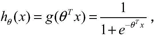
Specifically, the origin of the classification criteria: logistic regression aims to learn an 0/1 classification model from features, and the model takes linear combination of characteristics as independent variables, and the value range of the independent variables is negative infinity to positive infinity. Therefore, a logistic function (or referred to as sigmoid function, i.e. a
Where x is an n-dimensional feature vector and function g is the logistic function) maps the arguments to (0,1), the mapped value is considered to be the probability of y ═ 1. The data samples are said to be linearly separable if a linear function can separate the samples, which we term is linearly branchingThe support vector machine corresponds to a straight line which can correctly divide data and has the largest interval, and the specific solving method is to obtain the dual problem of the maximum interval optimization problem (convex quadratic programming problem) by using a Lagrange multiplier method to obtain the super surface (w)
Tt
i+ b ═ 0) satisfies the w values under categories +1 and-1.
Compared with other classification algorithms, the SVM has the advantages of processing a linear inseparable sample set and avoiding overfitting. The SVM classifier is used to find an optimal hyperplane that can separate two classes of samples. SVM classification is described below.
A Support Vector Machine (SVM) is a two-classification model, and aims to find a hyperplane to segment a sample, wherein the segmentation principle is interval maximization, and the hyperplane is finally converted into a convex quadratic programming problem to be solved; the method is a supervised learning method and is mainly used for classification and regression analysis. The models from simple to complex include: when the training samples are linearly separable, learning a linearly separable support vector machine through hard interval maximization; when the training samples are approximately linearly separable, a linear support vector machine is learned through soft interval maximization; when the training samples are linearly infeasible, a nonlinear support vector machine is learned through kernel skills and soft interval maximization.
Assume that the training data set of L samples is (t)i,yi) 1,2, L, wherein ti∈RdIs a feature vector, yiE { +1, -1} is the corresponding label. The optimal hyperplane has the formula wTtiAnd + b is 0. To prevent sample marginalization, the following constraints exist:
yi(wTti+b)≥1,i=1,2,...,L;
H
1and H
2The distance between can be calculated as:
the maximized distance ρ is equal to the minimized parameter w. Thus, the optimization problem can be equivalently converted into the following:
s.t.yi(wTti+b)≥1,i=1,2,...,L
the optimization problem is then solved by a quadratic programming method, obtaining parameters w and b, where w is a vector representing the separating hyperplane.
The above is the basic linear SVM classification. In fact, most of the time the data is not linearly separable, the hyperplane that satisfies this condition does not exist at all. In the case of nonlinear data, one approach to SVM is to select a kernel function and map the data to a high-dimensional space to solve the problem of inseparability of linearity in the original space. Specifically, under the condition of inseparability, a support vector machine firstly completes calculation in a low-dimensional space, then maps an input space to a high-dimensional feature space through a kernel function, and finally constructs an optimal separation hyperplane in the high-dimensional feature space, so that nonlinear data which are not easily separated on a plane are separated. Another approach is to handle outlier (outliers) methods using relaxation variables: for the case of non-linear data, which may not be due to the non-linear structure of the data itself, but simply to the noise of the data. Resulting in data points that are far from the normal position, which we call outlier, in our original SVM model, the existence of outlier is likely to have a large influence, because the hyperplane itself is composed of only a few supported vectors, and if outlier exists in these supported vectors, the influence is large. To deal with this situation, the SVM allows the data points to deviate somewhat from a lower hyperplane, introducing a relaxation variable ξiAnd (6) solving.
Assuming that phi denotes a feature, the kernel function k (x, y) becomes phi (x)TPhi (y). By considering the soft margin and the kernel skill approach, the optimization problem can be redefined as:
s.t.yi(wTφ(xi)+b)≥1-ξi,i=1,...,L
wherein, C is a preset parameter. It will be appreciated that although the above description considers only the two-classification problem, it can be easily extended to a variety of classifications by the "one-to-all" approach.
Step S103 specifically includes the following steps:
s1031, determining a plurality of candidate relays of the multi-relay network, wherein the candidate relays comprise two or more relays;
s1032, determining a candidate channel sample according to the candidate relay, and determining a first eigenvector according to a diagonal element of a covariance matrix of the candidate channel sample;
s1033, constructing a first classification model based on data driving, inputting the first feature vector into the first classification model, and outputting to obtain a corresponding first relay index, wherein the first relay index is used for maximizing the achievable rate of the corresponding candidate channel sample;
s1034, predicting and obtaining the optimal relay according to the first relay index and the first optimization model.
Specifically, in the embodiment of the present invention, the first classification model adopts an SVM classification model (i.e. an SVM classifier), and diagonal elements of a channel covariance matrix
Actually used as input to the SVM classifier to determine the optimal relay; the output of the SVM classifier is an index representing the selected relay that maximizes the achievable rate of the input channel. Typically, a multi-relay network has more than two relay selection candidates.
In the embodiment of the invention, a plurality of channel samples are generated for training. Each sample is a combination of more than two candidate relays. Suppose the candidate relay is denoted as { (h)1,g1),...,(hk,gk) K1, 2,. K, rootRandomly generating channel h according to Rayleigh fading characteristicskAnd gk. Then, a covariance matrix is constructed, and diagonal elements of the covariance matrix are extracted to represent the eigenvectors.
To reduce the impact of high-value feature variations, normalization may be performed on each feature. For each candidate channel sample, a global optimal design based on relay selection of an exhaustive search method and cooperative beam forming joint optimization is used to determine which relay can reach the maximum achievable rate under the constraint of transmission power, namely, the optimal relay can be determined.
It can be understood that, according to the training strategy provided above, each channel implementation is mapped to an optimal relay index, and according to a first relay index output by an SVM classifier, a relay selection constraint of a first optimization model can be determined, and an achievable rate of a corresponding relay can be solved under the condition of determining the relay selection constraint, so that an optimal relay of a multi-relay network system model can be predicted by comparing the achievable rates of different relays. Subsequent comparisons can be made to map the channel vector to Wk,WkIs the beamforming matrix on the selected relay (e.g., the kth relay). The training method provided by the embodiment of the invention reduces the learning burden of the SVM classifier, so that the SVM classifier is easier to train and obtains better effect in practice.
And S104, outputting a relay selection result of the multi-relay network according to the optimal relay.
The embodiment of the invention provides a method based on SVM (support vector machine) to design joint relay selection and cooperative beam forming so as to reduce the online calculation burden of a multi-antenna multi-relay network and simultaneously maintain the system performance. Joint optimization of relay selection and cooperative beamforming is very complex in terms of both objective function and constraints, because there is a coupling between the binary variable of relay selection and the continuous variable of beamforming. To map CSI to optimal relays with beamforming weights requires the establishment of a complex and elaborate learning system and is difficult to produce with satisfactory results. The embodiment of the invention provides a method for solving the problem by using a support vector machine method, and the method is practical and effective. The core idea of the classification method based on the Support Vector Machine (SVM) is to train the optimal parameters of the SVM classifier through a large amount of off-line sample data. In this way, the calculation of relay selection can be transferred to the offline SVM classifier, and the calculation time is saved. The embodiment of the invention also has the advantage of reducing the system complexity in the wireless sensor network and the Internet of things (IoT) network.
The embodiment of the invention models the relay selection problem into a multi-class classification problem, and adopts a multi-class classification technology based on data driving to solve the relay selection problem, thereby predicting the optimal relay which can maximize the achievable rate of the multi-relay network under the constraint of the transmitting power, saving the calculation time on one hand, reducing the calculation force requirement on the system, and improving the transmission efficiency and the transmission reliability of signals on the other hand.
As a further optional implementation, the relay selection method further includes the following steps:
and according to the optimal relay, deriving the optimal cooperative beamforming weight in an approximate form by adopting an algorithm based on the generalized Rayleigh quotient.
Specifically, in order to effectively select the optimal relay and derive the relevant beamforming matrix to achieve the design goal of maximum achievable rate, the embodiment of the present invention designs an SVM-based method to implement mapping from channel vectors to relay selection solutions, and once the optimal relay is selected, an algorithm based on a generalized rayleigh quotient can be used to derive the optimal cooperative beamforming weights in approximate form for the selected relay.
Referring to fig. 3, an embodiment of the present invention provides a relay selection system based on data driving, including:
the multi-relay network system model establishing module is used for establishing a multi-relay network system model and determining a first receiving signal and a first signal-to-noise ratio of a destination according to the multi-relay network system model;
the first optimization model building module is used for building a first optimization model according to the first received signal and the first signal-to-noise ratio, and the optimization goal of the first optimization model is the maximization of the achievable rate of the multi-relay network;
the optimal relay determining module is used for constructing a first classification model based on data driving and predicting to obtain an optimal relay according to the first classification model and the first optimization model;
and the output module is used for outputting the relay selection result of the multi-relay network according to the optimal relay.
The contents in the above method embodiments are all applicable to the present system embodiment, the functions specifically implemented by the present system embodiment are the same as those in the above method embodiment, and the beneficial effects achieved by the present system embodiment are also the same as those achieved by the above method embodiment.
Referring to fig. 4, an embodiment of the present invention provides a relay selection apparatus based on data driving, including:
at least one processor;
at least one memory for storing at least one program;
when the at least one program is executed by the at least one processor, the at least one program may cause the at least one processor to implement the relay selection method based on data driving.
The contents in the above method embodiments are all applicable to the present apparatus embodiment, the functions specifically implemented by the present apparatus embodiment are the same as those in the above method embodiments, and the advantageous effects achieved by the present apparatus embodiment are also the same as those achieved by the above method embodiments.
Embodiments of the present invention also provide a computer-readable storage medium, in which a processor-executable program is stored, and the processor-executable program is configured to execute the above-mentioned relay selection method based on data driving when executed by a processor.
The computer-readable storage medium according to the embodiment of the present invention is capable of executing the relay selection method based on data driving provided by the method embodiment of the present invention, and capable of executing any combination of the implementation steps of the method embodiment, and has corresponding functions and advantages of the method.
The embodiment of the invention also discloses a computer program product or a computer program, which comprises computer instructions, and the computer instructions are stored in a computer readable storage medium. The computer instructions may be read by a processor of a computer device from a computer-readable storage medium, and executed by the processor to cause the computer device to perform the method illustrated in fig. 1.
In alternative embodiments, the functions/acts noted in the block diagrams may occur out of the order noted in the operational illustrations. For example, two blocks shown in succession may, in fact, be executed substantially concurrently, or the blocks may sometimes be executed in the reverse order, depending upon the functionality/acts involved. Furthermore, the embodiments presented and described in the flow charts of the present invention are provided by way of example in order to provide a more thorough understanding of the technology. The disclosed methods are not limited to the operations and logic flows presented herein. Alternative embodiments are contemplated in which the order of various operations is changed and in which sub-operations described as part of larger operations are performed independently.
Furthermore, although the present invention is described in the context of functional modules, it should be understood that, unless otherwise stated to the contrary, one or more of the above-described functions and/or features may be integrated in a single physical device and/or software module, or one or more of the functions and/or features may be implemented in a separate physical device or software module. It will also be appreciated that a detailed discussion of the actual implementation of each module is not necessary for an understanding of the present invention. Rather, the actual implementation of the various functional modules in the apparatus disclosed herein will be understood within the ordinary skill of an engineer, given the nature, function, and internal relationship of the modules. Accordingly, those skilled in the art can, using ordinary skill, practice the invention as set forth in the claims without undue experimentation. It is also to be understood that the specific concepts disclosed are merely illustrative of and not intended to limit the scope of the invention, which is defined by the appended claims and their full scope of equivalents.
The above functions, if implemented in the form of software functional units and sold or used as a separate product, may be stored in a computer-readable storage medium. Based on such understanding, the technical solution of the present invention may be embodied in the form of a software product, which is stored in a storage medium and includes instructions for causing a computer device (which may be a personal computer, a server, or a network device) to execute all or part of the steps of the above method according to the embodiments of the present invention. And the aforementioned storage medium includes: a U-disk, a removable hard disk, a Read-Only Memory (ROM), a Random Access Memory (RAM), a magnetic disk or an optical disk, and other various media capable of storing program codes.
The logic and/or steps represented in the flowcharts or otherwise described herein, e.g., an ordered listing of executable instructions that can be considered to implement logical functions, can be embodied in any computer-readable medium for use by or in connection with an instruction execution system, apparatus, or device, such as a computer-based system, processor-containing system, or other system that can fetch the instructions from the instruction execution system, apparatus, or device and execute the instructions. For the purposes of this description, a "computer-readable medium" can be any means that can contain, store, communicate, propagate, or transport the program for use by or in connection with the instruction execution system, apparatus, or device.
More specific examples (a non-exhaustive list) of the computer-readable medium would include the following: an electrical connection (electronic device) having one or more wires, a portable computer diskette (magnetic device), a Random Access Memory (RAM), a read-only memory (ROM), an erasable programmable read-only memory (EPROM or flash memory), an optical fiber device, and a portable compact disc read-only memory (CDROM). Further, the computer readable medium could even be paper or another suitable medium upon which the above described program is printed, as the program can be electronically captured, via for instance optical scanning of the paper or other medium, then compiled, interpreted or otherwise processed in a suitable manner if necessary, and then stored in a computer memory.
It should be understood that portions of the present invention may be implemented in hardware, software, firmware, or a combination thereof. In the above embodiments, the various steps or methods may be implemented in software or firmware stored in memory and executed by a suitable instruction execution system. For example, if implemented in hardware, as in another embodiment, any one or combination of the following techniques, which are known in the art, may be used: a discrete logic circuit having a logic gate circuit for implementing a logic function on a data signal, an application specific integrated circuit having an appropriate combinational logic gate circuit, a Programmable Gate Array (PGA), a Field Programmable Gate Array (FPGA), or the like.
In the foregoing description of the specification, reference to the description of "one embodiment/example," "another embodiment/example," or "certain embodiments/examples," etc., means that a particular feature, structure, material, or characteristic described in connection with the embodiment or example is included in at least one embodiment or example of the invention. In this specification, schematic representations of the above terms do not necessarily refer to the same embodiment or example. Furthermore, the particular features, structures, materials, or characteristics described may be combined in any suitable manner in any one or more embodiments or examples.
While embodiments of the present invention have been shown and described, it will be understood by those of ordinary skill in the art that: various changes, modifications, substitutions and alterations can be made to the embodiments without departing from the principles and spirit of the invention, the scope of which is defined by the claims and their equivalents.
While the preferred embodiments of the present invention have been illustrated and described, it will be understood by those skilled in the art that various changes in form and details may be made therein without departing from the spirit and scope of the invention as defined by the appended claims.


