CN112897210B - Communication cable's book covers device - Google Patents
Communication cable's book covers device Download PDFInfo
- Publication number
- CN112897210B CN112897210B CN202110224308.4A CN202110224308A CN112897210B CN 112897210 B CN112897210 B CN 112897210B CN 202110224308 A CN202110224308 A CN 202110224308A CN 112897210 B CN112897210 B CN 112897210B
- Authority
- CN
- China
- Prior art keywords
- mounting seat
- fixed mounting
- waist
- support
- block
- Prior art date
- Legal status (The legal status is an assumption and is not a legal conclusion. Google has not performed a legal analysis and makes no representation as to the accuracy of the status listed.)
- Active
Links
Images


Classifications
-
- B—PERFORMING OPERATIONS; TRANSPORTING
- B65—CONVEYING; PACKING; STORING; HANDLING THIN OR FILAMENTARY MATERIAL
- B65H—HANDLING THIN OR FILAMENTARY MATERIAL, e.g. SHEETS, WEBS, CABLES
- B65H54/00—Winding, coiling, or depositing filamentary material
- B65H54/02—Winding and traversing material on to reels, bobbins, tubes, or like package cores or formers
- B65H54/28—Traversing devices; Package-shaping arrangements
- B65H54/2821—Traversing devices driven by belts or chains
-
- B—PERFORMING OPERATIONS; TRANSPORTING
- B65—CONVEYING; PACKING; STORING; HANDLING THIN OR FILAMENTARY MATERIAL
- B65H—HANDLING THIN OR FILAMENTARY MATERIAL, e.g. SHEETS, WEBS, CABLES
- B65H54/00—Winding, coiling, or depositing filamentary material
- B65H54/02—Winding and traversing material on to reels, bobbins, tubes, or like package cores or formers
- B65H54/40—Arrangements for rotating packages
- B65H54/44—Arrangements for rotating packages in which the package, core, or former is engaged with, or secured to, a driven member rotatable about the axis of the package
-
- B—PERFORMING OPERATIONS; TRANSPORTING
- B65—CONVEYING; PACKING; STORING; HANDLING THIN OR FILAMENTARY MATERIAL
- B65H—HANDLING THIN OR FILAMENTARY MATERIAL, e.g. SHEETS, WEBS, CABLES
- B65H2701/00—Handled material; Storage means
- B65H2701/30—Handled filamentary material
- B65H2701/34—Handled filamentary material electric cords or electric power cables
Landscapes
- Seats For Vehicles (AREA)
- Electric Cable Installation (AREA)
Abstract
The invention discloses a communication cable rolling device, which relates to the technical field of communication cable production equipment and comprises a movable mounting seat and a fixed mounting seat of a clamping shaft frame, and a rotating shaft which is arranged at the end of the fixed mounting seat and drives the shaft frame to rotate, wherein the movable mounting seat and the fixed mounting seat are provided with a clamping support for drawing the shaft frame near the discharge end of the shaft frame, the clamping support horizontally reciprocates left and right, the clamping support is rotatably connected with a cylindrical connecting block, the cylindrical connecting block is arranged on the movable support, a waist-shaped groove is arranged in the movable support, a first chain wheel and a second chain wheel are respectively arranged at the two ends of the waist-shaped groove, chains are arranged on the second chain wheel and the first chain wheel, the cylindrical connecting block is rotatably connected with one chain link in the chains, when the rotating speed of the rotating shaft changes, the moving speed of the clamping support also changes, manual adjustment is not needed, and the communication cable rolling device has good self-adapting effect, the efficiency that the cable conductor book was covered is improved, has guaranteed the quality of cable conductor simultaneously, avoids the cable conductor to appear dragging the damage.
Description
Technical Field
The invention belongs to the technical field of communication cable production equipment, and particularly relates to a communication cable rolling device.
Background
At present, with the continuous development of communication technology, people have more and more applications to communication equipment, and for the communication technology, a communication cable is an indispensable transmission equipment of the communication technology, and can transmit not only telephone, telegraph, fax files and the like, but also television and radio programs, data and other electric signals. Which is generally formed by twisting more than one pair of mutually insulated wires. Compared with an overhead open wire, the communication cable has the advantages of large communication capacity, high transmission stability, good confidentiality, less influence of natural conditions and external interference and the like, and is usually rolled and arranged on a reel during the processing of the communication cable in order to facilitate the transportation and the laying of the communication cable.
Chinese patent CN110817582A discloses a coiling mechanism is used in communication cable production, and the problem neat inadequately when rolling to the cable now proposes following scheme, including fixed frame and reel, be equipped with actuating mechanism on the bottom inner wall of fixed frame, actuating mechanism is used for driving the reel and rotates, there is the push rod motor through the bolt fastening on the inner wall of one side of fixed frame, and the sleeve has been cup jointed to the one end of push rod motor extension rod, and it has first annular spout to open on the telescopic circumference outer wall, be equipped with one-level stop gear on the inner wall of one side of fixed frame, be equipped with second grade stop gear on the top inner wall of fixed frame. When the cable winding device is used for winding a cable, one end of the cable is clamped on one side of the first annular chute, the cable can slide relative to the first annular chute, when the winding drum is driven by the servo motor to rotate, the push rod motor drives the sleeve and the cable to reciprocate above two ends of the winding drum, so that the cable is flatly laid on the outer wall of the winding drum, the cable is prevented from being accumulated at one position of the winding drum, the winding drum and the push rod are driven by the independent motors, the two driving motors are required to be always in a balanced and related synchronous speed, when the speed of a previous process of communicating the cable is changed, namely, the speed is increased or decreased, the cable is required to be stopped to adjust the speed again, the operation is inconvenient, and the production efficiency is reduced. Therefore, we propose a reeling device for communication cables.
Disclosure of Invention
In view of the shortcomings in the prior art, the present invention is directed to a communication cable reeling device to solve the above problems.
The purpose of the invention can be realized by the following technical scheme: a communication cable winding device comprises a movable mounting seat and a fixed mounting seat for clamping a shaft bracket, and a rotating shaft which is arranged at the end of the fixed mounting seat and drives the shaft bracket to rotate, wherein the movable mounting seat and the fixed mounting seat are provided with a clamping support for drawing the shaft bracket near the discharge end of the shaft bracket, the clamping support horizontally reciprocates left and right, the clamping support is rotationally connected with the cylindrical connecting block, the cylindrical connecting block is arranged on the movable support, a waist-shaped groove is arranged in the movable support, a first chain wheel and a second chain wheel are respectively arranged at two ends of the waist-shaped groove, the second chain wheel is arranged close to the fixed mounting seat side, chains are arranged on the second chain wheel and the first chain wheel, a fixing plate is arranged among the first chain wheel, the chain and the second chain wheel, the cylindrical connecting block is arranged in a gap between the chain and the waist-shaped groove, and the cylindrical connecting block is rotationally connected with one chain link in the chain;
the side, close to the fixed mounting seat, of the movable support seat is provided with a waist-shaped plate, one end of the waist-shaped plate is rotatably connected with the movable support seat, a rotating shaft for driving a shaft bracket to rotate is arranged in the middle of the fixed mounting seat, the fixed mounting seat is provided with a first sleeve coaxial with the rotating shaft, a bearing is arranged between the rotating shaft and the first sleeve, the rotating shaft is provided with a torque sensor, the other end of the waist-shaped plate is rotatably connected with the first sleeve in a sleeved mode, and one side of the waist-shaped plate is provided with an adjusting box for adjusting the angle of the waist-shaped plate;
a first bevel gear is arranged on the side, away from the clamping support, of the second chain wheel, a second bevel gear is meshed and connected to one side of the first bevel gear, a rotating shaft provided with the second bevel gear is installed in a second sleeve of the movable support, the second bevel gear is rotatably connected with the second sleeve, a synchronous belt pulley is fixedly connected to the rotating shaft provided with the second bevel gear and close to the shoulder waist-shaped plate end, and the synchronous belt pulley is connected with a synchronous belt pulley fixedly connected to the side, away from the shaft bracket, of the rotating shaft through a synchronous belt;
the movable support is characterized in that a supporting sliding seat capable of sliding up and down is arranged at the bottom end of the movable support, the bottom end of the movable support is connected with the top end of the supporting sliding seat in a sliding mode, the supporting sliding seat is contained in a T-shaped sliding groove formed in the fixed mounting seat and close to the side face of the movable support, and the supporting sliding seat vertically slides up and down along the arc-shaped groove.
As a further scheme of the invention, a first large gear coaxial with the rotating shaft is arranged on the side of the waist-shaped plate far away from the fixed mounting seat, a first small gear is arranged on the side of the first large gear far away from the waist-shaped plate and fixedly connected with the rotating shaft, a second small gear is arranged on the outer side of the first large gear, the first large gear is meshed with the second small gear, a second large gear is arranged on one side of the first small gear, the first small gear is meshed with the second large gear, the second large gear and the second small gear are coaxially arranged and fixedly connected with a push rod which is arranged on the adjusting box and rotates, the first small gear is a tooth-lacking gear, the modules and sizes of the first large gear and the second large gear are consistent, the modules and sizes of the first small gear and the second small gear are consistent, and a rotation limiting mechanism is arranged on the push rod.
As a further scheme of the invention, a ratchet wheel is fixedly connected to the push rod, a rotatable ratchet rod is arranged on one side of the ratchet wheel, the ratchet rod is rotatably connected with the side plate of the adjusting box, and a torque spring is arranged at the rotating position of the ratchet rod and the adjusting box.
As a further scheme of the invention, the bottom of the adjusting box is connected with a transverse plate arranged on the fixed mounting seat in a sliding manner, a push block is arranged on the side, away from the rotating shaft, of the adjusting box, the push block slides along the axial direction of the shaft bracket, and the push block is in sliding fit with the inclined surface of the adjusting box to drive the adjusting box to horizontally slide along the radial direction of the fixed mounting seat.
As a further scheme of the invention, the push block is slidably connected with the fixed mounting seat, the fixed mounting seat is provided with a mounting hole for accommodating the push block along the axis direction of the shaft bracket, the push block is arranged in the mounting hole and penetrates through the fixed mounting seat to be in contact with a side plate of the shaft bracket, the contact end of the push block and the shaft bracket is provided with a spherical block, the spherical block is in rolling connection with the push block, and when the shaft bracket is mounted on the fixed mounting seat, the shaft bracket extrudes the push block to drive the adjusting box to move close to the side of the waist-shaped plate, so that the first large gear is meshed with the second small gear.
As a further scheme of the invention, a connecting block is arranged on the side of the push block close to the spherical block, a second spring is arranged between the connecting block and the fixed mounting seat, a first spring is arranged on the side of the adjusting box far from the waist-shaped plate, and the first spring is fixedly connected with the fixed mounting seat.
As a further scheme of the invention, a cylinder is arranged on the side, close to the fixed mounting seat, of the waist-shaped plate, an arc-shaped groove capable of containing the cylinder is formed on the side, close to the waist-shaped plate, of the fixed mounting seat, and the cylinder slides along the arc-shaped groove.
As a further scheme of the invention, the cylinder is fixedly connected with one end of a pull wire, the other end of the pull wire is fixedly connected with a wire spool, the wire spool is fixedly connected with a push rod, and the wire spool is accommodated in a groove formed in the fixed mounting seat.
As a further scheme of the invention, a waist-shaped hole is formed in the side plate, close to the fixed mounting seat, of the adjusting box, the waist-shaped hole is positioned below the ratchet rod, and the waist-shaped hole is internally provided and is detachably connected with the fixed mounting seat.
As a further scheme of the invention, the clamping support is provided with a clamping block, the bottom end of the clamping block and the clamping support are combined to clamp a fixing hole of the cable, the top of the clamping block is provided with a third spring, and the third spring is arranged between the top end of the clamping block and the clamping support.
The invention has the beneficial effects that: the torque sensor is arranged on the rotating shaft, the rotating speed of the motor is automatically adjusted through the change of the torque, and the offline speed of the cable in the previous process is automatically adapted to the offline speed of the cable in the previous process, so that the phenomenon that the cable is pulled by a shaft bracket due to the fact that the previous process is too slow is avoided, the quality of the cable is influenced, meanwhile, when the rotating speed of the rotating shaft changes, the moving speed of the clamping support is changed along with the change of the rotating speed of the rotating shaft, manual adjustment is not needed, the self-adaptive effect is good, the cable winding efficiency is improved, and the quality of the cable is guaranteed; along with the going on that the pedestal was rolled up and is covered, the thickness of cable line constantly increases on the pedestal, through adjusting box drive waist shape board clockwise rotation, the height of removal support is raised to the intermittent type formula to avoid the cable conductor to be too big because of the difference in height of centre gripping support, and lead to producing the friction increase between cable conductor and the centre gripping support, reduced and held the friction between support and the cable conductor, thereby reduced the cable conductor and rolled up the defective rate that covers the in-process, guaranteed the quality.
Drawings
In order to more clearly illustrate the embodiments or technical solutions in the prior art of the present invention, the drawings used in the description of the embodiments or prior art will be briefly described below, and it is obvious for those skilled in the art that other drawings can be obtained based on these drawings without creative efforts.
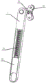
FIG. 1 is a schematic view of the overall structure of the present invention;
FIG. 2 is a schematic view of another embodiment of the present invention;
FIG. 3 is a schematic view of the construction of the conditioning case of the present invention;
FIG. 4 is a schematic structural view of a fixing bar of the present invention;
FIG. 5 is an enlarged schematic view of FIG. 3A;
FIG. 6 is a schematic view of the construction of the clamping shoe of the present invention;
FIG. 7 is a schematic structural view of a push block of the present invention;
FIG. 8 is a schematic view of the construction of the support pole of the present invention;
FIG. 9 is a schematic structural view of a fixing bar of the present invention;
FIG. 10 is a schematic illustration of the construction of the waist panel of the present invention;
in the figure: a movable mounting seat-1, a shaft bracket-2, a fixed mounting seat-3, a movable support-4, a clamping support-5, a waist-shaped plate-6, a stay wire-7, an adjusting box-8, a first bevel gear-9, a second bevel gear-10, a spool-11, a supporting slide seat-12, a synchronous pulley-13, a synchronous belt-14, a push block-15, a first spring-16, a second spring-17, a motor-18, a rotating shaft-19, a stop lever 20, a T-shaped chute-31, an arc-shaped groove-32, a mounting hole-33, a first sleeve-34, a first chain wheel-41, a chain-42, a second chain wheel-43, a second sleeve-44, a waist-shaped groove-45, a fixed plate-46, a third spring-51, a third spring, The device comprises a clamping block-52, a cylindrical connecting block-53, a cylinder-61, a first gearwheel-81, a first pinion-82, a second gearwheel-83, a second pinion-84, a ratchet-85, a ratchet rod-86, a kidney-shaped hole-87, a push rod-88, a fixed round rod-111, a connecting block-151, a spherical block-152 and a positioning block-191.
Detailed Description
The technical solutions in the embodiments of the present invention will be clearly and completely described below with reference to the drawings in the embodiments of the present invention, and it is obvious that the described embodiments are only a part of the embodiments of the present invention, and not all of the embodiments. All other embodiments, which can be derived by a person skilled in the art from the embodiments given herein without making any creative effort, shall fall within the protection scope of the present invention.
Referring to fig. 1 to 10, in an embodiment of the present invention, a communication cable winding device includes a movable mounting seat 1 and a fixed mounting seat 3 for clamping a shaft frame 2, and a rotating shaft 19 installed at an end of the fixed mounting seat 3 for driving the shaft frame 2 to rotate, a clamping support 5 for pulling the shaft frame 2 is installed at a position, close to a discharge end of the shaft frame 2, of the movable mounting seat 1 and the fixed mounting seat 3, the clamping support 5 horizontally reciprocates left and right, the clamping support 5 is rotatably connected to a cylindrical connecting block 53, the cylindrical connecting block 53 is installed on a movable support 4, a waist-shaped groove 45 is formed in the movable support 4, a first sprocket 41 and a second sprocket 43 are respectively installed at two ends of the waist-shaped groove 45, the second sprocket 43 is installed close to the fixed mounting seat 3, a chain 42 is installed on the second sprocket 43 and the first sprocket 41, a fixing plate 46 is installed among the first sprocket 41, the chain 42 and the second sprocket 43, the cylindrical connecting block 53 is arranged in a gap between the chain 42 and the waist-shaped groove 45, and the cylindrical connecting block 53 is rotationally connected with one chain link in the chain 42;
a waist-shaped plate 6 is arranged on the side, close to the fixed mounting seat 3, of the movable support 4, one end of the waist-shaped plate 6 is rotatably connected with the movable support 4, a rotating shaft 19 for driving the shaft bracket 2 to rotate is arranged in the middle of the fixed mounting seat 3, a first sleeve 34 coaxial with the rotating shaft 19 is arranged on the fixed mounting seat 3, a bearing is arranged between the rotating shaft 19 and the first sleeve 34, a torque sensor is arranged on the rotating shaft 19, the other end of the waist-shaped plate 6 is rotatably connected with the first sleeve 34 in a sleeved mode outside the first sleeve 34, and an adjusting box 8 is arranged on one side of the waist-shaped plate 6 for adjusting the angle of the waist-shaped plate 6;
the second chain wheel 43 is provided with a first bevel gear 9 far away from the clamping support 5, one side of the first bevel gear 9 is engaged with a second bevel gear 10, a rotating shaft of the second bevel gear 10 is installed in a second sleeve 44 of the movable support 4, the second bevel gear 10 is rotatably connected with the second sleeve 44, a rotating shaft provided with the second bevel gear 10 is fixedly connected with a synchronous pulley 13 by virtue of a shoulder waist plate 6, and the synchronous pulley 13 is connected with a synchronous pulley 13 fixedly connected with the rotating shaft 19 far away from the shaft bracket 2 through a synchronous belt 14.
In the actual working process, the empty shaft bracket 2 is installed at the side of the movable installation seat 1, the shaft bracket 2 is sleeved on the fixed round rod 111, then the movable installation seat 1 and the fixed installation seat 3 are installed and fixed in a matching way, so that the other end of the shaft bracket 2 is fixedly connected with the rotating shaft 19 installed on the fixed installation seat 3, and the positioning hole on the shaft bracket 2 is installed in a matching way with the positioning block 191 of the rotating shaft 19, as shown in fig. 1, the cable passes through the clamping support 5 from the wire feeding process end and is fixed on the shaft bracket 2, the rotating shaft 19 is driven to rotate clockwise by the motor 18 installed at the end of the rotating shaft 19, the rotating shaft 19 drives the shaft bracket 2 to rotate clockwise, the cable is wound on the shaft bracket 2, the rotating shaft 19 rotates to drive the second bevel gear 10 to rotate by the synchronous belt 14 and the synchronous belt pulley 13, the second bevel gear 10 drives the first bevel gear 9 to rotate, the first bevel gear 9 drives the second chain wheel 43 to rotate, the second chain wheel 43 drives the chain 42 to rotate, so that the clamping support 5 is driven to horizontally reciprocate left and right, cables are uniformly wound on the shaft frame 2, a torque sensor is mounted at the output shaft end of the motor 18, the rotating speed of the motor 18 is automatically adjusted through the change of the torque of the motor 18, and the offline speed of the cable former process is automatically adapted to, so that the phenomenon that the shaft frame 2 pulls the cables due to the fact that the former process is too slow is avoided, the quality of the cables is influenced, meanwhile, when the rotating speed of the motor 18 changes, the moving speed of the clamping support 5 is changed along with the change of the rotating speed, manual adjustment is not needed, a good self-adaptive effect is achieved, the winding efficiency of the cables is improved, and the quality of the cables is guaranteed; going on along with the reel of pedestal 2 is covered, the thickness of cable continuously increases on the pedestal 2, through adjusting box 8 drive waist shaped plate 6 clockwise turning, the height of removal support 4 is raised to the intermittent type formula to avoid the cable conductor because of the difference in height of centre gripping support 5 is too big, lead to the cable conductor damaged.
Preferably, as shown in fig. 3 and 4, a first large gear 81 coaxial with the rotating shaft 19 is disposed on the side of the waist plate 6 away from the fixed mounting seat 3, a first small gear 82 is disposed on the side of the first large gear 81 away from the waist plate 6, the first small gear 82 is fixedly connected with the rotating shaft 19, a second small gear 84 is disposed on the outer side of the first large gear 81, the first large gear 81 is in meshed connection with the second small gear 84, a second large gear 83 is disposed on one side of the first small gear 82, the first small gear 82 is in meshed connection with the second large gear 83, the second large gear 83 and the second small gear 84 are coaxially disposed and are both fixedly connected with a push rod 88 rotating on the adjusting box 8, the first small gear 82 is a gear with missing teeth, a rotation limiting mechanism is disposed on the push rod 88, the rotating shaft 19 rotates the first small gear 82, because the first small gear 82 is a gear with missing teeth, the second large gear 83 is intermittently triggered to rotate, the second large gear 83 drives the push rod 88 to rotate, the push rod 88 drives the second small gear 84 to rotate, the second small gear 84 and the first large gear 81 are meshed for transmission to drive the first large gear 81 to rotate, so that the waist-shaped plate 6 is driven to rotate, the modulus and the size of the first large gear 81 and the second large gear 83 are consistent, the modulus and the size of the first small gear 82 and the second small gear 84 are consistent, the rotation angle of the waist-shaped plate 6 is matched with the increase of the cable thickness of the shaft bracket 2 through combination, and meanwhile, the push rod 88 is provided with a limiting mechanism to ensure that the push rod 88 cannot be reversed.
Preferably, as shown in fig. 4, a ratchet 85 is fixedly connected to the push rod 88, a rotatable ratchet rod 86 is disposed on one side of the ratchet 85, the ratchet rod 86 is rotatably connected to a side plate of the adjustment box 8, a torque spring is disposed at a rotation position of the ratchet rod 86 and the adjustment box 8, and the rotation prevention of the push rod 88 is realized by the combination of the ratchet 85 and the ratchet rod 86.
Preferably, as shown in fig. 2 and 4, the bottom of the adjusting box 8 is slidably connected with a transverse plate arranged on the fixed mounting seat 3, a push block 15 is arranged on the side of the adjusting box 8 far from the rotating shaft 19, the push block 15 slides along the axial direction of the shaft bracket 2, the push block 15 is slidably matched with an inclined surface of the adjusting box 8 to drive the adjusting box 8 to horizontally slide along the radial direction of the fixed mounting seat 3, the adjusting box 8 is driven to move left and right by moving the push block 15, after the cable winding in the shaft bracket 2 is finished, the movable mounting seat 1 and the fixed mounting seat 3 are disassembled, the shaft bracket 2 is taken out, meanwhile, the movable support 4 needs to be restored to the initial position, the push block 15 is separated from the adjusting box 8 by moving the push block 15, then the adjusting box 8 is moved right, so that the first large gear 81 and the second small gear 84 are separated from the mesh, the second large gear 83 is separated from the first small gear 82 and falls back to the initial position under the action of gravity of the movable support 4, when the shaft bracket 2 is re-installed in the movable installation seat 1, the push block 15 is pushed to drive the adjusting box 8 to move leftwards, so that the first large gear 81 is meshed with the second small gear 84, and the second large gear 83 is meshed with the first small gear 82.
In some embodiments, as shown in fig. 2 and 8, the pushing block 15 is slidably connected to the fixed mounting base 3, the fixed mounting base 3 is provided with a mounting hole 33 for accommodating the pushing block 15 along the axial direction of the shaft bracket 2, the pushing block 15 is disposed in the mounting hole 33 and penetrates through the fixed mounting base 3 to contact with a side plate of the shaft bracket 2, a spherical block 152 is disposed at a contact end of the pushing block 15 and the shaft bracket 2, the spherical block 152 is in rolling connection with the pushing block 15, abrasion between the shaft bracket 2 and the spherical block 152 is reduced, when the shaft bracket 2 is mounted on the fixed mounting base 3, the shaft bracket 2 presses the pushing block 15 to drive the adjusting box 8 to move close to the waist-shaped plate 6, so that the first large gear 81 is engaged with the second small gear 84.
Preferably, as shown in fig. 4, a connecting block 151 is disposed on the pushing block 15 near the spherical block 152, a second spring 17 is disposed between the connecting block 151 and the fixed mounting seat 3, when the pushing block 15 is pressed by the shaft bracket 2, the second spring 17 is in a compressed state, after the shaft bracket 2 is disassembled, the pushing block 15 moves toward the shaft bracket 2 under the elastic force of the second spring 17 so as to be separated from the adjusting box 8, a first spring 16 is disposed on the adjusting box 8 far from the waist plate 6, the first spring 16 is fixedly connected with the fixed mounting seat 3, when the second pinion 84 in the adjusting box 8 is engaged with the first gearwheel 81, the first spring 16 is in a stretched state, when the adjusting box 8 is separated from the pushing block 15, the adjusting box 8 moves rightward under the elastic force of the first spring 16 so that the second pinion 84 is separated from the first gearwheel 81, and both the first spring 16 and the second spring 17 play a restoring role.
Preferably, as shown in fig. 3, a cylinder 61 is arranged on the side of the waist-shaped plate 6 close to the fixed mounting seat 3, an arc-shaped groove 32 capable of accommodating the cylinder 61 is formed on the side of the fixed mounting seat 3 close to the waist-shaped plate 6, and the cylinder 61 slides along the arc-shaped groove 32, so that the rotation stability of the waist-shaped plate 6 is improved.
In some embodiments, as shown in fig. 2 and 4, the cylinder 61 is fixedly connected with one end of the stay wire 7, the other end of the stay wire 7 is fixedly connected with the spool 11, the pulley is arranged at the position of the inflection point of the stay wire 7, so that friction and abrasion of the stay wire 7 are reduced, the spool 11 is fixedly connected with the push rod 88, the spool 11 is accommodated in the groove formed in the fixed mounting seat 3, that is, when the creel 2 is wound and accommodated with cables, the push rod 88 is driven to rotate clockwise, the push rod 88 drives the spool 11 to rotate clockwise, the waist-shaped plate 6 is driven to rotate clockwise through the stay wire 7, so that the movable support 4 is driven to raise slowly, the torque of the push rod 88 is relieved, and the stability of rotation of the waist-shaped plate 6 is improved.
Preferably, as shown in fig. 4 and 5, a waist-shaped hole 87 is formed in a side plate of the adjusting box 8 close to the fixed mounting seat 3, the waist-shaped hole 87 is located below the ratchet rod 86, a stop rod 20 is arranged in the waist-shaped hole 87, the stop rod 20 is detachably connected with the fixed mounting seat 3, when the adjusting box 8 moves rightwards, the stop rod 20 contacts with the bottom surface of the ratchet rod 86 to press the ratchet rod 86 to move upwards to separate from the ratchet 85, so that the push rod 88 is separated from the limit, and under the action of gravity of the waist-shaped plate 6, the synchronous belt 14 is driven to rotate anticlockwise to pay off.
Preferably, as shown in fig. 1, a supporting slide 12 capable of sliding up and down is arranged at the bottom end of the movable support 4, the bottom end of the movable support 4 is connected with the top end of the supporting slide 12 in a sliding manner, the supporting slide 12 is accommodated in a T-shaped chute 31 formed in the fixed mounting seat 3 close to the side surface of the movable support 4, the supporting slide 12 vertically slides up and down along the T-shaped chute, and the supporting slide 12 plays a role of limiting the movable support 4, i.e., the movable support 4 is kept horizontally parallel, so that the movable support 4 is prevented from rotating when the kidney-shaped plate 6 rotates.
Preferably, as shown in fig. 6, a clamping block 52 is arranged on the clamping support 5, the bottom end of the clamping block 52 and the clamping support 5 are combined to clamp a fixing hole of a cable, a third spring 51 is arranged at the top of the clamping block 52, the third spring 51 is arranged between the top end of the clamping block 52 and the clamping support 5, a soft foam block is arranged on the bottom surface of the clamping block 52 to prevent the cable from being worn and damaged, meanwhile, the clamping block 52 clamps the cable under the action of the third spring 51 to prevent the cable from falling off from the clamping support 5 after the cable is cut, and the cable cutting device is suitable for cables with different diameters, and has a wide application range.
The working principle of the invention is as follows: the rotating shaft 19 is driven by the motor 18 to rotate clockwise, the rotating shaft 19 drives the shaft bracket 2 to rotate clockwise, the cable wire is wound and stored on the shaft bracket 2, the rotating shaft 19 rotates to drive the second bevel gear 10 to rotate through the matching of the synchronous belt 14 and the synchronous belt wheel 13, the second bevel gear 10 drives the first bevel gear 9 to rotate, the first bevel gear 9 drives the second chain wheel 43 to rotate, the second chain wheel 43 drives the chain 42 to rotate, so as to drive the clamping support 5 to reciprocate horizontally and leftwards and rightwards, so that the cable wire is uniformly wound and covered on the shaft bracket 2, the rotating speed of the motor 18 is automatically adjusted through the change of the torque of the motor 18 by installing a torque sensor at the output shaft end of the motor 18, the inserting speed of the cable wire previous process is automatically adapted, the pulling phenomenon of the shaft bracket 2 caused by the too slow previous process is avoided, the quality of the cable wire is influenced, meanwhile, when the rotating speed of the motor 18 changes, the moving speed of the clamping support 5 also changes, the cable winding and covering device has the advantages that manual adjustment is not needed, a good self-adaptive effect is achieved, the cable winding and covering efficiency is improved, and meanwhile the quality of a cable is guaranteed; going on along with the reel of pedestal 2 is covered, the thickness of cable continuously increases on the pedestal 2, through adjusting box 8 drive waist shaped plate 6 clockwise turning, the height of removal support 4 is raised to the intermittent type formula to avoid the cable conductor because of the difference in height of centre gripping support 5 is too big, lead to the cable conductor damaged.
In the description of the present invention, it is to be understood that the terms "upper", "lower", "left", "right", etc., indicating an orientation or positional relationship are based on the orientation or positional relationship shown in the drawings and are used merely for convenience in describing the present invention and for simplifying the description, but do not indicate or imply that the device or element referred to must have a specific orientation, be constructed in a specific orientation, or be operated, and thus, should not be construed as limiting the present invention.
Furthermore, the method is simple. The terms "first", "second" and "first" are used for descriptive purposes only and are not to be construed as indicating or implying relative importance or implicitly indicating the number of technical features indicated. In the description of the present invention, "a plurality" means two or more unless specifically limited otherwise.
It will be appreciated by those skilled in the art that various changes, modifications, substitutions and alterations can be made in these embodiments without departing from the principles and spirit of the invention. The present embodiments are, therefore, to be considered in all respects as illustrative and not restrictive, the scope of the invention being indicated by the appended claims rather than by the foregoing description, and all changes which come within the spirit and scope of the invention, and any equivalents thereto, such as those skilled in the art, are intended to be embraced therein.
Claims (7)
1. The utility model provides a device is covered to communication cable's book, includes movable mounting seat (1) and fixed mounting seat (3) of centre gripping pedestal (2) to and install at fixed mounting seat (3) end drive pedestal (2) pivoted pivot (19), its characterized in that, movable mounting seat (1) and fixed mounting seat (3) are close to pedestal (2) ejection of compact line end and are equipped with traction cable's centre gripping support (5), reciprocating motion about centre gripping support (5) level, centre gripping support (5) are connected with cylinder connecting block (53) rotation, cylinder connecting block (53) are installed on moving support (4), it has waist type groove (45) to have seted up in moving support (4), waist type groove (45) both ends are equipped with first sprocket (41) and second sprocket (43) respectively, second sprocket (43) are close to fixed mounting seat (3) side-mounting, a chain (42) is mounted on the second chain wheel (43) and the first chain wheel (41), a fixing plate (46) is arranged among the first chain wheel (41), the chain (42) and the second chain wheel (43), the cylindrical connecting block (53) is arranged in a gap between the chain (42) and the waist-shaped groove (45), and the cylindrical connecting block (53) is rotatably connected with one chain link in the chain (42);
the waist-shaped plate is arranged on the side, close to the fixed mounting seat (3), of the movable support (4), one end of the waist-shaped plate (6) is rotatably connected with the movable support (4), a rotating shaft (19) for driving the shaft bracket (2) to rotate is arranged in the middle of the fixed mounting seat (3), a first sleeve (34) coaxial with the rotating shaft (19) is arranged on the fixed mounting seat (3), a bearing is arranged between the rotating shaft (19) and the first sleeve (34), a torque sensor is arranged on the rotating shaft (19), the other end of the waist-shaped plate (6) is sleeved on the outer side of the first sleeve (34) and is rotatably connected with the first sleeve (34), and an adjusting box (8) is arranged on one side of the waist-shaped plate (6) to adjust the angle of the waist-shaped plate (6);
a first bevel gear (9) is arranged on the side, far away from the clamping support (5), of the second chain wheel (43), a second bevel gear (10) is connected to one side of the first bevel gear (9) in a meshed mode, a rotating shaft provided with the second bevel gear (10) is installed in a second sleeve (44) of the movable support (4), the second bevel gear (10) is rotatably connected with the second sleeve (44), a synchronous pulley (13) is fixedly connected to the rotating shaft provided with the second bevel gear (10) close to the waist plate (6), and the synchronous pulley (13) is connected with the synchronous pulley (13) fixedly connected to the side, far away from the shaft bracket (2), of the rotating shaft (19) through a synchronous belt (14);
a supporting sliding seat (12) capable of sliding up and down is arranged at the bottom end of the movable support (4), the bottom end of the movable support (4) is connected with the top end of the supporting sliding seat (12) in a sliding mode, the supporting sliding seat (12) is contained in a T-shaped sliding groove (31) formed in the fixed mounting seat (3) and close to the side face of the movable support (4), and the supporting sliding seat (12) vertically slides up and down along the T-shaped sliding groove (31);
fixed mounting seat (3) side is kept away from to waist board (6) and is equipped with first gear wheel (81) coaxial with pivot (19), waist board (6) side is kept away from in first gear wheel (81) is equipped with first pinion (82), first pinion (82) and pivot (19) fixed connection, first gear wheel (81) outside is equipped with second pinion (84), first gear wheel (81) and second pinion (84) meshing connection, first pinion (82) one side is equipped with second gear wheel (83), first pinion (82) and second gear wheel (83) meshing connection, second gear wheel (83) and second pinion (84) coaxial setting all with establish pivoted push rod (88) fixed connection on adjusting box (8), first pinion (82) are the scarce tooth gear, first gear wheel (81) and second gear wheel (83) modulus and size are unanimous, the modulus and the size of the first pinion (82) and the second pinion (84) are consistent, and a rotation limiting mechanism is arranged on the push rod (88).
2. The communication cable reeling device according to claim 1, wherein a ratchet wheel (85) is fixedly connected to the push rod (88), a rotatable ratchet rod (86) is arranged on one side of the ratchet wheel (85), the ratchet rod (86) is rotatably connected with a side plate of the adjusting box (8), and a torsion spring is arranged at a rotating position of the ratchet rod (86) and the adjusting box (8).
3. The winding device of the communication cable according to claim 2, wherein the bottom of the adjusting box (8) is slidably connected with a transverse plate arranged on the fixed mounting seat (3), a pushing block (15) is arranged on the side, away from the rotating shaft (19), of the adjusting box (8), the pushing block (15) slides along the axial direction of the shaft bracket (2), and the pushing block (15) is slidably matched with the inclined surface of the adjusting box (8) to drive the adjusting box (8) to horizontally slide along the radial direction of the fixed mounting seat (3).
4. The winding device of the communication cable according to claim 3, wherein the pushing block (15) is connected with the fixed mounting seat (3) in a sliding manner, the fixed mounting seat (3) is provided with a mounting hole (33) for accommodating the pushing block (15) along the axial direction of the shaft bracket (2), the pushing block (15) is arranged in the mounting hole (33) and penetrates through the fixed mounting seat (3) to be in contact with a side plate of the shaft bracket (2), a spherical block (152) is arranged at the contact end of the pushing block (15) and the shaft bracket (2), the spherical block (152) is in rolling connection with the pushing block (15), and when the shaft bracket (2) is mounted on the fixed mounting seat (3), the shaft bracket (2) extrudes the pushing block (15) to drive the adjusting box (8) to move close to the waist-shaped plate (6), so that the first large gear (81) is meshed with the second small gear (84).
5. The winding device of the communication cable according to claim 4, wherein the pushing block (15) is provided with a connecting block (151) near the spherical block (152), a second spring (17) is arranged between the connecting block (151) and the fixed mounting seat (3), the adjusting box (8) is provided with a first spring (16) far away from the waist-shaped plate (6), and the first spring (16) is fixedly connected with the fixed mounting seat (3).
6. A communication cable reeling device according to claim 2, wherein the waist plate (6) is provided with a cylinder (61) near the fixed mounting seat (3), the fixed mounting seat (3) is provided with an arc-shaped groove (32) near the waist plate (6) for accommodating the cylinder (61), and the cylinder (61) slides along the arc-shaped groove (32).
7. A communication cable reeling device according to claim 1, wherein the clamping support (5) is provided with a clamping block (52), the bottom end of the clamping block (52) is combined with the clamping support (5) to clamp the fixing hole of the cable, the top of the clamping block (52) is provided with a third spring (51), and the third spring (51) is arranged between the top end of the clamping block (52) and the clamping support (5).
Priority Applications (1)
| Application Number | Priority Date | Filing Date | Title |
|---|---|---|---|
| CN202110224308.4A CN112897210B (en) | 2021-03-01 | 2021-03-01 | Communication cable's book covers device |
Applications Claiming Priority (1)
| Application Number | Priority Date | Filing Date | Title |
|---|---|---|---|
| CN202110224308.4A CN112897210B (en) | 2021-03-01 | 2021-03-01 | Communication cable's book covers device |
Publications (2)
| Publication Number | Publication Date |
|---|---|
| CN112897210A CN112897210A (en) | 2021-06-04 |
| CN112897210B true CN112897210B (en) | 2022-01-04 |
Family
ID=76107311
Family Applications (1)
| Application Number | Title | Priority Date | Filing Date |
|---|---|---|---|
| CN202110224308.4A Active CN112897210B (en) | 2021-03-01 | 2021-03-01 | Communication cable's book covers device |
Country Status (1)
| Country | Link |
|---|---|
| CN (1) | CN112897210B (en) |
Families Citing this family (3)
| Publication number | Priority date | Publication date | Assignee | Title |
|---|---|---|---|---|
| CN113548545A (en) * | 2021-08-06 | 2021-10-26 | 内蒙古万琪机械加工股份有限公司 | Cable coiling and uncoiling device |
| CN115583534B (en) * | 2022-10-31 | 2024-04-05 | 华能澜沧江水电股份有限公司 | Cable pulling and winding device |
| CN116022598B (en) * | 2023-02-17 | 2023-06-02 | 国网山西省电力公司吕梁供电公司 | Cable winding equipment for conveying station |
Family Cites Families (6)
| Publication number | Priority date | Publication date | Assignee | Title |
|---|---|---|---|---|
| WO2009141794A2 (en) * | 2008-05-20 | 2009-11-26 | Schleuniger Holding Ag | Cable transport device |
| CN106348092B (en) * | 2016-10-17 | 2019-03-15 | 太原理工大学 | A kind of automatic rope withdrawing apparatus of pit rope of band row rope function |
| CN108892009A (en) * | 2018-08-14 | 2018-11-27 | 中国电子科技集团公司第三十八研究所 | A kind of active automatic line arranging mechanism and the capstan winch with the mechanism |
| CN110550501A (en) * | 2019-07-19 | 2019-12-10 | 安徽嘉明新材料科技有限公司 | Polyester rope winding and collecting device and operation method thereof |
| CN111874736A (en) * | 2020-06-24 | 2020-11-03 | 浙江莱尼新材料科技有限公司 | Cable winding machine |
| CN112061866B (en) * | 2020-08-24 | 2022-06-21 | 山东九州电力线缆有限公司 | Cable winding equipment |
-
2021
- 2021-03-01 CN CN202110224308.4A patent/CN112897210B/en active Active
Also Published As
| Publication number | Publication date |
|---|---|
| CN112897210A (en) | 2021-06-04 |
Similar Documents
| Publication | Publication Date | Title |
|---|---|---|
| CN112897210B (en) | Communication cable's book covers device | |
| CN102024525B (en) | Film sintering machine | |
| CN110902486A (en) | Winding device for straw bundling rope production and use method thereof | |
| CN213387177U (en) | A coiling mechanism for shielded cable production | |
| CN210418701U (en) | Data line processingequipment with adjustable density degree | |
| CN211569776U (en) | Cable paying-off mechanism | |
| CN210824827U (en) | Efficient winding device for producing wire harnesses and cables | |
| CN212953472U (en) | Adjustable cable pay-off rack | |
| CN213170963U (en) | Cable take-up device for monitoring | |
| CN113734905B (en) | Full-automatic wire rewinding machine | |
| CN214326814U (en) | Cable fixing device that electric power engineering used | |
| CN212450057U (en) | Enameled wire winding device | |
| CN213738048U (en) | Coiling mechanism is used in wire and cable production | |
| CN114822997A (en) | Wire stranding equipment for producing wires and cables | |
| CN112047192A (en) | Winder for building | |
| CN220731241U (en) | Cantilever type cabling machine | |
| CN220578596U (en) | Flexible cable winding device | |
| CN218289936U (en) | Winding mechanism for electric power engineering design | |
| CN220710023U (en) | Semi-automatic double-station stranding machine | |
| CN220392978U (en) | Waterproof wire arranging mechanism for winding and unwinding cables | |
| CN214779852U (en) | Draw gear for electric power construction | |
| CN220264707U (en) | Cable winding device | |
| CN219950070U (en) | Cable traction machine | |
| CN214827886U (en) | Adjustable wire releasing device for wire and cable production | |
| CN218809574U (en) | Steel wire rope winding equipment |
Legal Events
| Date | Code | Title | Description |
|---|---|---|---|
| PB01 | Publication | ||
| PB01 | Publication | ||
| SE01 | Entry into force of request for substantive examination | ||
| SE01 | Entry into force of request for substantive examination | ||
| GR01 | Patent grant | ||
| GR01 | Patent grant | ||
| TR01 | Transfer of patent right |
Effective date of registration: 20221108 Address after: No. 9, No. 587, Chenwang Road, Economic and Technological Development Zone, Changxing County, Huzhou City, Zhejiang Province, 313,100 Patentee after: ZHEJIANG LANGMAN COMMUNICATION TECHNOLOGY Co.,Ltd. Address before: 321000 80 Dongshan Road, Puyang Street, Pujiang County, Jinhua City, Zhejiang Province Patentee before: Chen Xujun |
|
| TR01 | Transfer of patent right |