CN112889118A - System for determining blood pressure of one or more users - Google Patents
System for determining blood pressure of one or more users Download PDFInfo
- Publication number
- CN112889118A CN112889118A CN201880097151.XA CN201880097151A CN112889118A CN 112889118 A CN112889118 A CN 112889118A CN 201880097151 A CN201880097151 A CN 201880097151A CN 112889118 A CN112889118 A CN 112889118A
- Authority
- CN
- China
- Prior art keywords
- module
- pulsatility
- signal
- user
- wearable device
- Prior art date
- Legal status (The legal status is an assumption and is not a legal conclusion. Google has not performed a legal analysis and makes no representation as to the accuracy of the status listed.)
- Pending
Links
Images


Classifications
-
- G—PHYSICS
- G16—INFORMATION AND COMMUNICATION TECHNOLOGY [ICT] SPECIALLY ADAPTED FOR SPECIFIC APPLICATION FIELDS
- G16H—HEALTHCARE INFORMATICS, i.e. INFORMATION AND COMMUNICATION TECHNOLOGY [ICT] SPECIALLY ADAPTED FOR THE HANDLING OR PROCESSING OF MEDICAL OR HEALTHCARE DATA
- G16H50/00—ICT specially adapted for medical diagnosis, medical simulation or medical data mining; ICT specially adapted for detecting, monitoring or modelling epidemics or pandemics
- G16H50/30—ICT specially adapted for medical diagnosis, medical simulation or medical data mining; ICT specially adapted for detecting, monitoring or modelling epidemics or pandemics for calculating health indices; for individual health risk assessment
-
- A—HUMAN NECESSITIES
- A61—MEDICAL OR VETERINARY SCIENCE; HYGIENE
- A61B—DIAGNOSIS; SURGERY; IDENTIFICATION
- A61B5/00—Measuring for diagnostic purposes; Identification of persons
- A61B5/02—Detecting, measuring or recording pulse, heart rate, blood pressure or blood flow; Combined pulse/heart-rate/blood pressure determination; Evaluating a cardiovascular condition not otherwise provided for, e.g. using combinations of techniques provided for in this group with electrocardiography or electroauscultation; Heart catheters for measuring blood pressure
- A61B5/0205—Simultaneously evaluating both cardiovascular conditions and different types of body conditions, e.g. heart and respiratory condition
-
- A—HUMAN NECESSITIES
- A61—MEDICAL OR VETERINARY SCIENCE; HYGIENE
- A61B—DIAGNOSIS; SURGERY; IDENTIFICATION
- A61B5/00—Measuring for diagnostic purposes; Identification of persons
- A61B5/0002—Remote monitoring of patients using telemetry, e.g. transmission of vital signals via a communication network
- A61B5/0015—Remote monitoring of patients using telemetry, e.g. transmission of vital signals via a communication network characterised by features of the telemetry system
- A61B5/002—Monitoring the patient using a local or closed circuit, e.g. in a room or building
-
- A—HUMAN NECESSITIES
- A61—MEDICAL OR VETERINARY SCIENCE; HYGIENE
- A61B—DIAGNOSIS; SURGERY; IDENTIFICATION
- A61B5/00—Measuring for diagnostic purposes; Identification of persons
- A61B5/02—Detecting, measuring or recording pulse, heart rate, blood pressure or blood flow; Combined pulse/heart-rate/blood pressure determination; Evaluating a cardiovascular condition not otherwise provided for, e.g. using combinations of techniques provided for in this group with electrocardiography or electroauscultation; Heart catheters for measuring blood pressure
- A61B5/021—Measuring pressure in heart or blood vessels
- A61B5/02108—Measuring pressure in heart or blood vessels from analysis of pulse wave characteristics
-
- A—HUMAN NECESSITIES
- A61—MEDICAL OR VETERINARY SCIENCE; HYGIENE
- A61B—DIAGNOSIS; SURGERY; IDENTIFICATION
- A61B5/00—Measuring for diagnostic purposes; Identification of persons
- A61B5/145—Measuring characteristics of blood in vivo, e.g. gas concentration, pH value; Measuring characteristics of body fluids or tissues, e.g. interstitial fluid, cerebral tissue
- A61B5/1455—Measuring characteristics of blood in vivo, e.g. gas concentration, pH value; Measuring characteristics of body fluids or tissues, e.g. interstitial fluid, cerebral tissue using optical sensors, e.g. spectral photometrical oximeters
- A61B5/14551—Measuring characteristics of blood in vivo, e.g. gas concentration, pH value; Measuring characteristics of body fluids or tissues, e.g. interstitial fluid, cerebral tissue using optical sensors, e.g. spectral photometrical oximeters for measuring blood gases
-
- A—HUMAN NECESSITIES
- A61—MEDICAL OR VETERINARY SCIENCE; HYGIENE
- A61B—DIAGNOSIS; SURGERY; IDENTIFICATION
- A61B5/00—Measuring for diagnostic purposes; Identification of persons
- A61B5/68—Arrangements of detecting, measuring or recording means, e.g. sensors, in relation to patient
- A61B5/6801—Arrangements of detecting, measuring or recording means, e.g. sensors, in relation to patient specially adapted to be attached to or worn on the body surface
- A61B5/6802—Sensor mounted on worn items
- A61B5/681—Wristwatch-type devices
-
- A—HUMAN NECESSITIES
- A61—MEDICAL OR VETERINARY SCIENCE; HYGIENE
- A61B—DIAGNOSIS; SURGERY; IDENTIFICATION
- A61B5/00—Measuring for diagnostic purposes; Identification of persons
- A61B5/68—Arrangements of detecting, measuring or recording means, e.g. sensors, in relation to patient
- A61B5/6801—Arrangements of detecting, measuring or recording means, e.g. sensors, in relation to patient specially adapted to be attached to or worn on the body surface
- A61B5/6813—Specially adapted to be attached to a specific body part
- A61B5/6824—Arm or wrist
Abstract
A system for determining a Blood Pressure (BP) of a user, the system comprising: for each user, a signal module (2) configured to cooperate with a wearable device (1), the wearable device (1) being designated to be worn on the user's wrist and comprising a pulsatility sensing unit (11); the signal module (2) comprises a control module (20), the control module (20) for controlling the pulsatility sensing unit (11) to measure a plurality of pulsatility signals (4) at the user's wrist; a processing module (21) for processing the pulsatility signal to obtain pulsatility signal data (22); and a communication module (3) for remote transmission of the pulsatile signal data (22); the system further comprises an external service module (5), the external service module (5) comprising a database storage system (51) for storing the transmitted pulsatile signal data (22) for each user in a database (53); and a calculation module (52) configured to calculate a BP value for each user based on pulsatility signal data (22) stored in a database (53).
Description
Technical Field
The present invention relates to a system for determining the blood pressure of one or more users.
Background
According to the world health organization, one of three adults worldwide suffers from hypertension. Hypertension can lead to serious complications such as stroke and heart failure. Each year, the disease causes 750 million premature deaths worldwide. The paradox of hypertension is that most people suffering from this condition do not realize it.
Furthermore, the current "gold standard" for Blood Pressure (BP) measurements is performed with cuffs placed around the arms. This 110 year history of technology is cumbersome and results in low compliance for patients prescribed for self-monitoring. As a result, health care professionals lack access to complete and high quality data for their diagnosis and treatment of the disease.
Disclosure of Invention
The present disclosure relates to a non-intrusive system for monitoring the BP of one or more users in a continuous and accurate manner.
More particularly, the present disclosure relates to a system for determining Blood Pressure (BP) of one or more users, the system comprising:
for each user, a signal module configured to cooperate with a wearable device, the wearable device being designated to be worn on the user's wrist and comprising a pulsatility sensing unit; the signal module comprises a control module configured to control the pulsatility sensing unit such that the pulsatility sensing unit measures a plurality of pulsatility signals at the user's wrist; a processing module configured for processing the pulsatile signal to obtain pulsatile signal data; and a communication module for remotely transmitting the pulsatile signal data;
the system further comprises: an external services module comprising a database storage system for storing the transmitted pulsatile signal data for each of the one or more users in a database; and a calculation module configured to calculate a BP value for each of the one or more users based on pulsatility signal data stored in a database.
In an embodiment, the pulsatility sensing unit may comprise an optical measurement sensor.
In another embodiment, the control module may be configured such that each of the plurality of pulsatility signals is measured during a predetermined measurement period. The control module may include a trigger module configured to initiate and end the measurement time period.
In yet another embodiment, the pulsatility signal data corresponds to the measured pulsatility signal, or the processing module may be configured to perform a pre-processing step on the measured pulsatility signal in order to obtain the pulsatility signal data.
In yet another embodiment, the signal module may cooperate with the wearable device via the first short-range communication link.
In yet another embodiment, the communication module may be included in a portable gateway device.
In yet another embodiment, the database storage system may be configured to store the pulsatile signal data for each user in a database.
In yet another embodiment, the system may be configured to input user-specific information for each of the one or more users.
In yet another embodiment, the calculation module is configured to calculate the BP value of the user based on pulsatile signal data stored in the database.
In yet another embodiment, the system may include a display interface configured to display the calculated BP value.
Drawings
The invention will be better understood with the aid of the description of an embodiment given by way of example and illustrated by the figures, in which:
FIG. 1 schematically shows a system for determining BP of one or more users, the system comprising a signal module, a communication module and an external service module, according to an embodiment;
FIG. 2 schematically shows details of a signal module according to an embodiment;
fig. 3 illustrates a possible configuration of a wearable device, which represents with which the signal module is designated to cooperate;
figure 4 shows a configuration of a pulsatile sensing unit comprising a PPG sensor according to an embodiment;
FIG. 5 shows a schematic representation of an external service module according to an embodiment;
fig. 6a and 6b report exemplary pulsatility signals as a function of time, respectively, measured by a pulsatility sensing unit on a wearable device;
fig. 7a reports an exemplary user activity level as a function of time, and fig. 7b shows pulsatility signal measurements triggered after a predetermined rest period;
FIG. 8a reports another exemplary user activity level as a function of time, FIG. 8b shows a detected "strenuous" exercise period, and FIG. 8c shows a pulsatile signal measurement triggered after a predetermined rest period;
FIG. 9 illustrates a flow diagram representing a decision tree for triggering measurement of pulsatility signals according to one embodiment;
fig. 10 illustrates an arrangement according to an embodiment in which the signal module is fully included in the wearable device;
fig. 11 illustrates an arrangement according to an embodiment, wherein at least a part of the signal module is comprised in a wearable device;
FIG. 12 illustrates a system including a portable gateway device according to one embodiment;
FIG. 13 shows a system including a portable gateway device according to another embodiment;
FIG. 14 shows a system including a portable gateway device according to yet another embodiment;
FIG. 15 illustrates a database of external service modules according to an embodiment; and
FIG. 16 illustrates a database of external service modules according to another embodiment.
Detailed Description
FIG. 1 schematically represents a system for determining a Blood Pressure (BP) value of one or more users according to an embodiment. For each user, the system comprises a signal module 2, the signal module 2 cooperating with a wearable device 1, the wearable device 1 being intended to be worn on the user's wrist and comprising a pulsatility sensing unit 11. Pulsatility sensing unit 11 may include an analog-to-digital converter module (not shown) that outputs pulsatility signal 4.
Fig. 2 shows a possible embodiment of the signal module 2. The signal module 2 comprises a control module 20, the control module 20 being configured to control the wearable device 1 such that the pulsatility sensing unit 11 measures the pulsatility signal 4 at the user's wrist when the wearable device 1 is worn. The signal module 2 further comprises a processing module 21, the processing module 21 being configured for processing the pulsatile signal in order to obtain pulsatile signal data 22.
Wearable device
A possible configuration of the wearable device 1 is illustrated in the cross-sectional view of fig. 3. The wearable device 1 may comprise a wristband 15, the wristband 15 containing the pulsatility sensing unit 11. In the particular example of fig. 3, wrist band 15 includes four pulsatility sensing units 11 distributed along the inside of the periphery of wrist band 15 so as to be in contact with the skin of the user's wrist when wearable device 1 is worn. Other arrangements of pulsatility sensing unit 11 on the armband are also possible. For example, the armband may include any number of pulsatility sensing units 11 in various configurations along the wrist band 15.
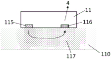
In one embodiment, the pulsatility sensing unit 11 may comprise a photoplethysmograph (PPG) sensor array which may measure arterial pulsation, arterial diameter, blood flow and/or blood content. In this embodiment, the pulsatile sensing unit 11 may be arranged on the wrist band 15 such that the optical sensor array 11 spans or otherwise addresses an artery near the ulna 113 (such as the ulnar artery 111), or the radial artery 112 near the radius 114 (as shown in fig. 3) wrist or any arterial vascular bed 117 of the wrist skin.
Details of a possible configuration of the PPG sensor 11 are shown in fig. 4. The PPG sensor 11 comprises at least one light source 115, and at least one photodetector 116 positioned adjacent to the light source 115. For example, the PPG sensor 11 may comprise two or more light sources emitting at the same wavelength or different wavelengths. The light source 115 may include a Light Emitting Diode (LED). The light source 115 may further include any other suitable source, such as a laser, an incandescent lamp, or ambient light. The photodetector 116 may comprise a phototransistor, a camera imaging device, or a Charge Coupled Device (CCD). The pulsatility sensing unit 11 may comprise any other suitable optical sensor, such as at least one of the following: a laser speckle sensor, a laser doppler sensor, or a camera.
The pulsatility signal 4 measured by the PPG sensor 11 may be defined as a signal containing information about the blood flow and the periodic variation of the arterial diameter of a given segment of the arterial tree. The periodic variation is typically generated by the arrival of a pressure pulse at a given segment of the arterial tree. In the configuration of fig. 3 and 4, the pulsatile signal 4 corresponds to a reflected light plethysmograph signal, wherein the light emitted by the light source 115 passes through the capillary bed 117 of the user's wrist skin. Other arrangements of the PPG sensor 11 are possible in order to measure the photoplethysmograph signal.
In other arrangements, the wearable device 1 may comprise a strip of material to be worn on another body part of the user. Examples of the wearable device 1 may include, but are not limited to: an armband, a headband, an ankle chain, a necklace and ring, a helmet, an ear plug, a hearing aid, an earphone, glasses, a shirt, a brassiere, clothing, a fingertip sensor, a glove, underpants, a socket, a shoe, a wearable sensor, a patch that is attached to the skin of a user, a bed sensor, a chair sensor, a toilet sensor, a table sensor, an automobile sensor, a computer mouse sensor, or any other arrangement intended to measure pulsatile signals.
For example, the wearable device 1 may comprise any existing device, including an armband device, a smart watch, or any or device worn at the user's wrist, and including a pulsatility sensing unit 11 adapted to measure pulsatility signals at the user's wrist.
In other arrangements, the wearable device 1 may include other types of sensors in addition to or instead of the pulsatility sensing unit 11, such as Galvanic Skin Response (GSR) sensor arrays, bioimpedance (BioZ) sensor arrays, Electrocardiography Sensors (ECGs), Radio Frequency (RF) detection based sensors, radar sensors, mechanical sensors, pressure sensors, invasive sensors, intra-arterial sensors, minimally invasive sensors, subcutaneous sensors, tonometers, strain sensors, plethysmographic sensors, microphones, ultrasound sensors, capacitive sensors, electromagnetic sensors, raman sensors, or any sensor capable of measuring pulsatility signals from the capillary bed of the skin or from any other part of the arterial tree.
Turning back to fig. 1, the system comprises an external service module 5, the external service module 5 being remote from the wearable device 1 and the signal module 2 and being configured for receiving pulsatile signal data 22 from the signal module 2.
A schematic representation of an external service module 5 according to an embodiment is shown in fig. 5. The external service module 5 comprises a database storage system 51, the database storage system 51 being configured to store the received pulsatile signal data 22 in a database 53. The external service module 5 further comprises a calculation module 52, the calculation module 52 being configured for calculating a BP value for each user based on the pulsatility signal data 22 stored in the database 53.
The external service module 5 is typically remote from the signal module 2. In an embodiment, the communication module 3 is used to transmit pulsatile signal data from the signal module 2 to the external service module 5. The external service module 5 may comprise one or more remote servers (or computers). One or more remote servers may be in a single location, or multiple remote servers may be geographically distributed (such as in a computer network or cloud computing). Database storage system 51, calculation module 52, and/or database 53 may be distributed across multiple remote servers.
As shown in fig. 1, a plurality of signal modules 2 each cooperating with the wearable device 1 may transmit their pulsatile signal data 22 to the external service module 5. Then, the database storage system 51 may store a set including a plurality of pulsatile signal data 22 obtained for each wearable device 1 (for each user).
Measurement trigger
In one embodiment, the control module 20 may be configured such that each of the plurality of pulsatility signals is measured during a predetermined measurement period.
Fig. 6a and 6b report an exemplary pulsatility signal 4 as a function of time, measured by the pulsatility sensing unit 11 on the wearable device 1, respectively. The scale on the ordinate corresponds to arbitrary intensity units. The pulsatility signal 4 may correspond to several measurements performed on the user during a measurement period. The pulsatility signal 4 may be measured periodically or aperiodically. The measurement period may be the same from pulsatile signal 4 to another, or may be different.
In one embodiment, control module 20 includes a trigger module 23 (see fig. 2), trigger module 23 configured to start or stop measuring pulsatility signal 4 via pulsatility sensing unit 11.
The trigger module 23 may control the pulsatility sensing unit 11 according to the trigger parameters. The trigger parameters may be specific to the user.
Examples of trigger parameters may include a trigger signal, such as a motion signal representing user movement. Such a motion signal may be measured by using a motion sensor 12 placed on the user, e.g. on the wearable device 1. The motion signal may be used to calculate an activity level of the user and an activity level compared to a threshold. The trigger module 23 may control the pulsatility sensing unit 11 such that pulsatility signal measurements are started or stopped when the activity level is above or below a threshold.
The motion signal and/or pulsatility signal 4 may be used to detect that the user is wearing a wearable device.
The motion sensors 12 may include any one of an Inertial Measurement Unit (IMU), an accelerometer, a gyroscope, a magnetometer, or a combination of these devices.
In another embodiment, the trigger parameter includes a trigger signal, such as geographic location information of the user. The geographical location information may be provided by a geographical location sensor 13 (such as a GPS device) worn by the user, for example the geographical location sensor 13 included on the wearable device 1. The geographical location information may be used, for example, to: measurements with the pulsatility sensing unit 11 are allowed when the user is in a given area (such as at home, in the workplace) and are blocked in other situations. The geographical location information may also be provided by any indoor positioning system (such as nodes from WiFi/LiFi access points, bluetooth beacons, or any other optical, radio, or acoustic positioning technology) that interfaces with a geographical location sensor 13 that is also worn by the user. The geographical position information may also be provided by any other positioning system, such as a magnetic or inertial positioning system, integrated in the geographical position sensor 13 also worn by the user. The geographical location information may be used, for example, to: measurements with the pulsatility sensing unit 11 are allowed when the user is in a given area (such as at home, in a workplace, at some living environment) and measurements are facilitated or prevented accordingly.
In yet another embodiment, the trigger parameter includes a trigger signal, such as behavioral information about the user. The behavior information may include: a known awake/asleep pattern of the user, a predetermined measurement schedule, or a specific measurement schedule. Known awake/sleep modes or active/sedentary modes can be manually introduced into the system (in database 53) or learned by the system. The predetermined measurement schedule may be introduced by a clinician, for example, depending on a medication schedule or on the needs of a particular survey to be performed on the user. The schedule may be fixed for a particular user or dynamically modified for survey needs. The specific measurement schedule may comprise a manually introduced measurement schedule depending on the user's work, home, leisure plan, the user's geo-location, or new events occurring in the user's life.
The behavioral information may further include a feature associated with the user schedule that automatically adapts the measurement frequency according to the planned activity.
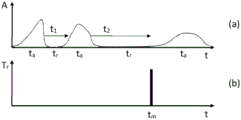
In yet another embodiment, the triggering parameters may include activity levels determined from the motion signal, and/or exercise detection. Here, the trigger parameter may be used in conjunction with a predetermined period of time during which the user is resting after the activity and/or exercise.
Fig. 7a reports an exemplary user activity level as a function of elapsed time calculated from a motion signal. In particular, FIG. 7a shows an activity time period t in which a user is activeaAnd a rest period t in which the user is at restr. Fig. 7b shows: upon rest period trIs longer than the predetermined rest period after the activity (second rest period t)2) The trigger module 23 triggers at the time tmThe pulsatility signal 4 is measured by the pulsatility detection unit 11. First rest period t1Is less than a predetermined rest period after the activity and does not initiate pulsatility signal measurements.
Fig. 8a reports another exemplary user activity level as a function of elapsed time calculated from the motion signal. FIG. 8b reports a detected "strenuous" exercise period teWhich may be calculated from the motion signal and/or the geographical position sensor 13 and corresponds to a user performing an activity with an intensity above a given intensity level. Fig. 8c shows that pulsatility signal measurement is triggered only when the following two criteria are met: rest period trIs longer than the predetermined rest period after the activity (second rest period t)2) And greater than the predetermined rest period (third rest period t) after the "strenuous" exercise3)。
Pulsatile signal measurements performed during "strenuous" exercise, during activities, and/or during any type of mental or cardiovascular stress are biased and may lead to erroneous clinical interpretation. The trigger parameters may thus be used to detect such pressure and further to track the elapsed time after the end of each of them. The system may then trigger the initiation of the measurement when the elapsed time is above a predetermined threshold. For example, according to criteria for measuring/monitoring blood pressure (such as "home blood pressure monitoring interpretation" of the uk hypertension association), the predetermined rest period after an activity may be about 5 minutes and the predetermined rest period after a "strenuous" exercise may be about 30 minutes.
In practice, the blood pressure measurement should be performed after the user has rested for at least 5 minutes and has not exercised for at least 30 minutes. The measurements performed during exercise and/or during any type of mental or cardiovascular stress are biased and may lead to erroneous interpretations. The trigger parameter may thus be used to detect such stress and further to track one or several elapsed time periods after the end of each of any type of activity or stress.
In yet another embodiment, the trigger parameters may include activity level and/or exercise detection in combination with at least one other trigger parameter (such as behavioral information, geographic location information, etc.). In fact, the trigger parameters may correspond to any criteria defined in the criteria. The trigger module 23 may use different trigger parameters in a hierarchical manner or in a decision tree manner in order to initiate pulsatility signal measurements.
Fig. 9 shows a flow chart representing a possible decision tree algorithm for triggering pulsatility signal measurements using at least two different trigger parameters. The trigger module 23 is idle (step (r)). Then, the trigger module 23 checks whether a trigger parameter including the behavior information is satisfied, for example, whether a criterion corresponding to a predetermined measurement schedule is satisfied (step (c)). The triggering module 23 then checks whether the conditions set by the triggering parameters including the activity level and/or the exercise detection in combination with the predetermined rest period are fulfilled (step (c)). Once the conditions of steps (c) and (c) are met, the measurement is started (step (c)).
In an embodiment, the trigger parameter may be transmitted to the external service module 5 via the communication module 3. The storage device 51 may then be configured to store the transmitted trigger parameters in the database 53.
In yet another embodiment, the triggering module 23 controls the pulsatility sensing unit 11 according to a manual input. The communication module 3 may be configured to transmit the trigger input to the external service module 5.
Pretreatment of
In an embodiment, the processing module 21 may be configured such that the measured pulsatility signal 4 is transmitted to the external service module 5 and stored in the database 53. In other words, no processing is performed on the "raw" pulsatility signal 4.
In an embodiment, the processing module 21 may be configured to perform a pre-processing step on the measured pulsatility signal 4 such that the pulsatility signal data 22 corresponds to the measured pulsatility signal 4 that has been submitted to the pre-processing step.
In a variant, the processing module 21 is configured to perform a pre-processing step on the measured pulsatility signal 4 in order to obtain the pulsatility signal data 22.
The pre-processing step comprises lossless compression of the measured pulsatility signal 4. Examples of such lossless compression are described in the following references: uthayakumar et al, "A surveon data compression techniques: from the sexual of data quality, coding schemes, data types and applications ", which was reported in https at 5 and 17 months in 2018: // doi.org/10.1016/j.jksuci.2018.05.006 are available online.
Alternatively, the pre-processing step comprises lossy compression of the measured pulsatility signal 4. Examples of such lossless compression are described in the same reference.
Alternatively, the preprocessing step comprises performing an ensemble averaging algorithm (ensemble averaging algorithm) on the measured pulsatility signal 4.
A possible integrated averaging algorithm may comprise the following steps:
identifying an individual arterial pulse in the sequence of optical signals (e.g., by detecting a local maximum or a local minimum of the signal);
selecting a window of data (e.g., a window length of 1 second) around each identified pulse;
weighting each individual pulse according to a reliability criterion (e.g., setting too noisy a pulse to "0");
overlapping the identified pulses, the pulses weighted by respective weighting factors; and
a most likely integrated average representing all pulses in the optical signal sequence is estimated (e.g., by performing an arithmetic average of the weighted pulses).
Buffer
In an embodiment, the signal module 2 is remote from the wearable device 1. The signal module 2 may communicate with the wearable device 1 via a first short-range communication link 25 (see fig. 1).
The first short-range communication link 25 may comprise an optical or radio wave communication device, notably using RFID and near field communication, bluetooth @ transmission protocol, Bluetooth Low Energy (BLE), near field communication protocol (NFC), proximity card or WiFi direct connection, Zigbee, power line communication, infrared transmission (IR), ultrasonic communication, Z-wave protocol, or any other home automation communication protocol.
The short-range communication link 25 may comprise a first short-range data buffer 24 (see fig. 2), the first short-range data buffer 24 being adapted to store the measured pulsatility signal 4 when the measured pulsatility signal 4 is not transmitted by the first short-range communication link 25. For example, the first short-range data buffer 24 may store the measured pulsatility signal 4 when the wearable device 1 and/or the signal module 2 are out of range or any of them are disabled, or the short-range communication link 25 is unavailable or inoperative.
The communication module 3 may be configured for: pulsatile signal data 22 is transmitted remotely from the signal module 2 to the external service module 5 via a long-range communication link 7 (see fig. 1). The long-range communication link 7 may comprise a mobile telephone network or a computer network using internet protocols.
The signal module 2 may comprise a long-range data buffer 26, the long-range data buffer 26 being adapted to: the pulsatile signal data 22 is stored when the pulsatile signal data 22 is not transmitted by the communication module 3 to the external service module 5. Likewise, the remote data buffer 26 may store pulsatile signal data 22 when the signal module 2 and/or the external service module 5 are out of range or either of them is disabled, or the remote communication link 7 is unavailable or inoperative.
The first short-range data buffer 24 and the long-range data buffer 26 may comprise areas of physical memory storage provided in the signal module 2 for temporarily storing the measured pulsatile signal 4 and pulsatile signal data 22, respectively, while not being transmitted by the short-range communication link 25 and the communication module 3, respectively. The first short and long range data buffers 24, 26 may be implemented in fixed memory locations in hardware or by using virtual data buffers in software that point to a location in physical memory.
Other arrangements of wearable devices and signal modules
In the embodiment illustrated in fig. 10, the signal module 2 is completely included in the wearable device 1. In the example shown, a control module 20, a processing module 21, a triggering module 23, a long-range data buffer 26 and a communication module 3. In this configuration, the short-range communication link 25 (and the first short-range data buffer 24) is not required, since the communication module 3 transmits pulsatile signal data 22 directly from the wearable device 1 towards the external service module 5 via the long-range communication link 7.
In another embodiment illustrated in fig. 11, at least a part of the signal module 2 is included in the wearable device 1, and another part is remote from the wearable device 1. In this example, the control module 20, the processing module 21, the triggering module 23 and the short-range communication link 25 (and possibly the first short-range data buffer 24) are comprised in the wearable device 1. The communication module 3 and possibly the long-range data buffer 26 are remote from the wearable device 1. Pulsatile signal data 22 is transmitted from the wearable device 1 to the communication module 3 via the short-range communication link 25.
The control module 20 may include a control firmware portion that may be included in the wearable device 1 and configured to cooperate with the wearable device 1.
The control module 20 may further include a control hardware portion, which may also be included in the wearable device 1.
In a further possible embodiment, the processing module 21 may comprise a processing firmware part that may be included in the wearable device 1.
In a further possible embodiment, the triggering module 23 may comprise a processing firmware part that may be included in the wearable device 1.
It should be understood that the firmware portion may also include middleware, software portion, or any executable code.
The first short-range communication link 25 may be placed between the portion of the signal module 2 included in the wearable device 1 and the portion remote from the wearable device 1. The first short-range data buffer 24 may then be between the part of the signal module 2 comprised in the wearable device 1 and the first short-range communication link 25. In the example of fig. 11, the first short-range data buffer 24 and the first short-range communication link 25 are between the processing module 21 and the communication module 3 (the latter being remote from the wearable device 1).
Portable gateway device
In an embodiment, the signal module 2 may be at least partially comprised in the portable gateway device 30. The portable gateway device 30 may comprise an electronic mobile device such as a smart phone, a tablet, a laptop, a desktop computer, or any other suitable device capable of communicating with the signal module 2 and the external service module 5.
In the embodiment of fig. 11, the communication module 3 (possibly with the long-range data buffer 26) is comprised in the portable gateway device 30, while the rest of the signal module 2 is comprised in the wearable device 1. In such a configuration, the communication module 3 may be part of a portable gateway device 30, such as an antenna in a smart phone. The first short-range communication link 25 may be included in the wearable device 1 and communicate with the portable gateway device 30.
The portable gateway device 30 may be configured to remotely transmit the pulsatile signal data 22 via a long-range communication link 7.
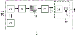
In another embodiment shown in fig. 12, the signal module 2 is remote from the wearable device 1 (such as in fig. 1), and the communication module 3 is included in the portable gateway device 30. The signal module 2 may include a second short-range communication link 27 for transmitting the processed data 22 to the portable gateway device 30. A second short-range data buffer 28 may then be placed before the second short-range communication link 27 to store the pulsatile signal data 22 when the second short-range communication link 27 is not transmitting pulsatile signal data 22.
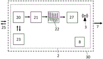
In another embodiment shown in fig. 13, the control module 20, the triggering module 23 and the first short-range communication link 25 (possibly with the first short-range data buffer 24) are comprised in the wearable device 1, while the remote portable gateway device 30 comprises the processing module 21 and the communication module 3. The portable gateway device 30 may further comprise a long-range data buffer 26 before the communication module 3.
In a further variant shown in fig. 14, the signal module 2 (including the communication module 3) may be fully included in the portable gateway device 30. In this configuration, the portable gateway device 30 may communicate with the wearable device 1 via the first short-range communication link 25 and with the external service module 5 via the long-range communication link 7 provided by the communication module 3. In this configuration, the second short-range communication link 27 and the second short-range data buffer 28 are not required.
The portable gateway device 30 may advantageously be used as an input means.
For example, the trigger input may be entered via the portable gateway device 30.
In a possible configuration, the motion sensor 12 may be included in the portable gateway device 30. For example, an accelerometer or a geolocation device in a smartphone may be used for this purpose. Alternatively, motion sensor 12 may be included in any other device, such as a commercial fitness tracker.
Database with a plurality of databases
The database storage system 51 is configured to store pulsatile signal data 22 in a database 53. FIG. 15 illustrates a database 53 of the database storage system 51 according to one embodiment.
Turning back to fig. 1, a plurality of signal modules 2, each cooperating with the wearable device 1, may transmit their pulsatile signal data 22 to the external service module 5. Then, the database storage system 51 may store a set including a plurality of pulsatile signal data 22 obtained for each wearable device 1 (for each user).
In the particular example of fig. 15, the database 53 stores a collection including a plurality of pulsatile signal data 22 obtained for a user. For example, for user a, the database 53 stores a set of pulsatile signal data 22 (ps 1, ps2, ps3 … …, or psi, where i =1 to n, where n is the number of measurements). For user B, the database 53 stores another set of pulsatility signal data 22 (psi, i =1 to n), and so on.
The database 53 may further store trigger parameters (indicated by the symbol "tpi" where i =1 to n) corresponding to each user and each set of pulsatile signal data 22.
The database storage system 51 may be further configured for: the trigger inputs are stored in a database 53 (not shown) for each user and set of pulsatile signal data 22.
The database storage system 51 may be configured such that a set of pulsatility signal data 22 corresponding to a user is stored in the database 53 separately from another set of pulsatility signal data 22 corresponding to another user.
User' sSpecific information
In an embodiment, the system is configured for entering user-specific information for each of the one or more users.
The user specific information may comprise any of the following: the type of wearable device worn by the user, age, weight, ethnicity information, gender, skin tone, cardiovascular condition, information related to the user's mood, food and beverage intake, the type of activity performed by the user, drug intake and dosage, weather, physical condition, alcohol consumption, smoking history, known health issues, health records, or combinations thereof.
The user specific information may further comprise one or more reference BP measurements. The reference BP measurement may be performed independently of the measurement with the pulsatility sensing unit 11.
The independent BP measurement may include: measurements performed using any suitable non-invasive measurement technique, including manual measurements by a health care professional, automated measurements by an automated arm cuff, automated measurements by an automated wrist cuff, or any suitable invasive measurement technique (including invasive arterial lines).
In the embodiment illustrated in fig. 6a, one or more reference BP measurements 6 are measured simultaneously with the measurement of the pulsatile signal 4.
In another embodiment illustrated in fig. 6b, the one or more reference BP measurements 6 are measured independently of the measurement of the pulsatile signal 4.
In yet another embodiment, the communication module 3 is configured to transmit said user specific information to the external service module 5. The database storage system 51 may then be configured such that the user-specific information corresponding to each set of pulsatile signal data 22 is stored in the database 53. In particular, user-specific information (indicated by the symbol "usi", where i =1 to n) corresponding to each pulsatile signal data 22 in the set of pulsatile signal data 22 may be stored in the database 53.
Computing
The external service module 5 further comprises a calculation module 52, the calculation module 52 being configured for calculating a BP value of the user based on the pulsatility signal data 22 stored in the database 53.
The external calculation module 52 may further be configured for calculating a quality indicator value of the pulsatility signal of the user based on the pulsatility signal data 22 stored in the database 53. A quality indicator value of the pulsatility signal may be calculated from the pulsatility signal 4 and may be used to quantify the quality of the measurement signal 4. The quality indicator value may be calculated from: the signal-to-noise ratio of the pulsatility signal, the likelihood that the pulsatility signal 4 can be analyzed by the calculation module 52, the presence of physiological features within the pulsatility signal 4 (e.g. physiological features described in european patent application EP 3226758), or any combination thereof. The quality signal values may also be stored as user specific information in the database 53.
In an embodiment, the calculation module 52 may be configured to calculate the BP value of the user based on a set comprising a plurality of pulsatile signal data 22 obtained for the user.
In a variation, the calculation module 52 may be configured to calculate the BP value of the user based on a subset of the set comprising the plurality of pulsatile signal data 22. In the example of fig. 15, the BP value (shown by the dotted square) of the user a is calculated by using a set including a plurality of pulsatility signal data 22 obtained for the user. In the case of the user C, the BP value is calculated by using a subset including two pulsatility signal data 22 obtained for the user.
In a further embodiment, the calculation module 52 may be configured to use BP values for users that include only a subset of the pulsatile signal data 22 (see fig. 15, user B). In this configuration, a BP value may be calculated for each measured pulsatility signal.
In another embodiment shown in fig. 16, the calculation module 52 may be configured to: the BP value for the selected user is calculated based on pulsatility signal data 22 from a subset of users, a subset of user parameters and/or user specific information (trigger parameters) stored in the database 53. Using pulsatility signal data 22 obtained from a subset of users, possibly in combination with a subset of user parameters and/or user specific information parameters, to calculate the BP value allows the performance of the calculation module 52 to be improved by providing more data for training the calculation technique. The subset of users may be clustered according to user specific information (users with the same skin tone, etc.) or according to triggering parameters (users for which pulsatility signal measurements are triggered in the same way).
The subset of users may be further clustered by using the clustering process disclosed in patent application US20130041268 or any other clustering or classification technique. As a cluster space, any combination of the following features may be used: the signal-to-noise ratio of the pulsatility signal data, the likelihood that the pulsatility signal data 22 can be analyzed by the calculation module 52, the presence of physiological features within the pulsatility signal (e.g. physiological features described in european patent application EP 3226758), or any other features that can be calculated from the pulsatility signal data 22. The pulsatile signal data 22 may be automatically clustered from different users.
The clustered pulsatile signal data 22 can then be used together to better train algorithms for those users. The clustered pulsatility signal data 22 is independent of the particular user or independent of the time at which the pulsatility signal 4 has been measured.
In yet another embodiment, the calculation module 52 may be configured to calculate the BP value of the user by further using user specific information. This step is also referred to as a calibration step, an initialization step or a re-initialization step.
In yet another embodiment, the calculation module 52 may be further configured to calculate the BP value of the user by further using the trigger input.
The calculation module 52 may be configured for calculating the BP value by using a pulse wave analysis technique, such as for example the pulse wave analysis technique described in european patent application EP 3226758.
The calculation module 52 may be further configured to calculate the BP value by using machine learning Techniques, such as described in "A Novel connections Blood Pressure Estimation application Based on Data Mining Techniques" of Fen Miao et al (IEEE Journal of biological and Health information, Volume: 21, Issue: 6, page 1730. sup. 1740, 2017).
In further embodiments, the calculation module 52 may be configured to calculate BP-related physiological parameters from the pulsatile signal, including any of systolic BP, diastolic BP, or mean arterial pressure.
The calculation module 52 may be further configured to calculate additional physiological parameters, including any of the following: pulse pressure, central pulse wave velocity, peripheral pulse wave velocity, arterial stiffness, aortic pulse transit time, augmentation index, cardiac volume change, pulse pressure change, cardiac output, systemic vascular resistance, venous pressure, systemic hemodynamic parameters, pulmonary hemodynamic parameters, cerebral hemodynamic parameters, heart rate variability, inter-beat intervals, arrhythmia detection, ejection duration, SpO2SpHb, SpMet, SpCO, respiration rate, tidal volume, apnea detection, sleep quality, sleep score, sleep analysis, time in bed, sleep duration, rem sleep time, light sleep time, deep sleep time, time to get up, time to fall asleep, sleep efficiency, number of minutes awake after sleep onset, snoring duration, stress index, and general cardiovascular and health index.
In another embodiment, the database storage system 51 may be configured to store the calculated BP value (represented by the symbol "BPi", where i =1 to n) and/or the additional physiological parameter in the database 53.
Display device
In an embodiment, the system may comprise a display interface 8 for displaying the calculated BP value and/or additional physiological parameters stored in the database 53.
The display interface 8 may be included in the external service module 5 (see fig. 5). The display interface 8 may comprise a web interface or similar connected software that may securely communicate with the external service module 5 (not shown). The clinician and/or user may connect to the external service module using a web page of the web interface and view the data included in the database 53. Alternatively, the display interface 8 may also be included in an application running on a portable gateway device 30 (such as a smartphone).
The display interface 8 may be included in the wearable device 1. The external service module 5 may then be configured to transmit the calculated BP value and/or additional physiological parameters to the wearable device 1 so that the latter may be displayed on the display interface 8.
The display interface 8 may be included in the portable gateway device 3. The external service module 5 may then be configured to transmit the calculated BP value and/or additional physiological parameters to the portable gateway device 3 so that the latter may be displayed on the display interface 8.
The external service module 5 may further be configured to transmit the calculated BP value to the portable gateway device 3. The transmitted calculated BP value may then be displayed on the portable gateway device 3.
Reference numerals
1 wearable device
11 pulsating sensing unit
110 wrist skin
111 ulnar artery
112 radial artery
113 ulna
114 radius
115 light source
116 photodetector
117 capillary bed
12 motion sensor
13 geographical position device
15 arm belt
2 signal module
20 control module
21 processing module
22 pulsatile signal data
23 trigger module
24 first short-range data buffer
25 first short-range communication link
26 remote data buffer
27 second short-range communication link
28 second short range data buffer
3 communication module
30 portable gateway device
4 pulsatility signal
5 external service module
51 database storage system
52 calculation module
53 database
6 independent BP measurement
7 telecommunication link
And 8, displaying an interface.
Claims (64)
1. A system for determining Blood Pressure (BP) of one or more users, the system comprising:
for each user, a signal module (2) configured to cooperate with a wearable device (1), the wearable device (1) being designated to be worn on the user's wrist and comprising a pulsatility sensing unit (11); the signal module (2) comprises a control module (20), the control module (20) being configured to control the pulsatility sensing unit (11) such that the pulsatility sensing unit (11) measures a plurality of pulsatility signals (4) at the user's wrist; a processing module (21) configured for processing the pulsatility signal to obtain pulsatility signal data (22); the signal module (2) further comprises a communication module (3) for remote transmission of the pulsatile signal data (22);
the system further comprises an external service module (5), the external service module (5) comprising a database storage system (51) for storing the transmitted pulsatile signal data (22) for each of the one or more users in a database (53); and a calculation module (52) configured to calculate a BP value for each of the one or more users based on pulsatility signal data (22) stored in a database (53).
2. The system as defined in claim 1, wherein the pulsatility sensing unit comprises an optical measurement sensor (11).
3. The system according to claim 2, wherein the optical measurement sensor (11) comprises a PPG sensor (115, 116) in contact with the wrist skin (110) when the wearable device (1) is worn.
4. A system as claimed in claim 3, wherein the optical measurement sensor (11) comprises a plurality of PPG sensors (115, 116) distributed around the wrist.
5. The system according to any one of claims 1 to 4, wherein the signal module (2) is remote from the wearable device (1).
6. The system according to any one of claims 1 to 4, wherein at least a part of the signal module (2) is comprised in the wearable device (1) and another part is remote from the wearable device (1).
7. The system of claim 6, wherein the control module (20), the processing module (21), the triggering module (23) and the short-range communication link (25) are comprised in the wearable device (1).
8. The system according to any one of claims 1 to 4, wherein the signal module (2) is completely comprised in the wearable device (1).
9. The system of any of claims 1 to 8, wherein the control module (20) comprises a control firmware portion.
10. The system according to any of claims 1 to 9, wherein the processing module (21) comprises a processing firmware part and/or the triggering module (23) comprises a processing firmware part.
11. The system of any one of claims 1 to 10, wherein the control module (20) is configured such that each of the plurality of pulsatility signals is measured during a predetermined measurement period.
12. The system according to claim 11, wherein the control module (20) comprises a trigger module (23), the trigger module (23) being configured to initiate and end the measurement time period.
13. The system as defined in claim 12, wherein the triggering module (23) controls the pulsatility sensing unit (11) in dependence of the triggering parameter.
14. The system of claim 13, wherein the wearable device (1) further comprises a motion sensor (12), the motion sensor (12) measuring a motion signal corresponding to the motion of the user when the wearable device (1) is worn, and
wherein the triggering parameter comprises a motion signal.
15. The system according to claim 13 or 14, wherein the wearable device (1) further comprises a geographical location means (13), the geographical location means (13) providing geographical location information when the wearable device (1) is worn, and
wherein the trigger parameter includes geographical location information.
16. The system of any of claims 13 to 15, wherein the trigger parameter comprises user-related behavior information.
17. The system of claim 16, wherein the user-related behavior information comprises any one of: a measurement schedule, an awake or asleep pattern, a user schedule.
18. The system according to any of claims 13 to 17, wherein the communication module (3) is configured for transmitting the trigger parameter to an external service module (5).
19. The system according to any one of claims 12 to 17, wherein the trigger module (23) controls the pulsatility sensing unit (11) according to a manually entered trigger input.
20. The system according to claim 19, wherein the communication module (3) is configured for transmitting the trigger input to an external service module (5).
21. The system of any one of claims 1 to 20, wherein the pulsatility signal data (22) corresponds to a measured pulsatility signal (4).
22. The system according to any one of claims 1 to 20, wherein the processing module (21) is configured to perform a pre-processing step on the measured pulsatility signal (4) in order to obtain the pulsatility signal data (22).
23. The system according to claim 22, wherein the preprocessing step comprises lossless compression of the measured pulsatility signal (4).
24. The system according to claim 22, wherein the preprocessing step comprises lossy compression of the measured pulsatility signal (4).
25. The system of claim 22, wherein the preprocessing step comprises performing an integrated averaging algorithm on the measured pulsatility signal (4).
26. The system according to claim 1 and claim 5, wherein the signal module (2) cooperates with the wearable device (1) via the first short-range communication link (25).
27. The system according to claim 1 and claim 6, wherein the part of the signal module (2) cooperates with the other part via a first short-range communication link (25).
28. The system of claim 26 or 27, wherein the signal module (2) comprises a first short-range data buffer (24), the first short-range data buffer (24) being adapted to store the measured pulsatility signal when the first short-range communication link (25) is not transmitting the measured pulsatility signal.
29. The system according to any one of claims 1 to 28, wherein the signal module (2) comprises a remote data buffer (26), the remote data buffer (26) being adapted to store pulsatile signal data (22) when the communication module (3) is not transmitting pulsatile signal data (22).
30. The system according to any one of claims 1 to 29, wherein the communication module (3) is comprised in a portable gateway device (30).
31. The system of claim 30, wherein the portable gateway device (30) comprises a smartphone or a tablet.
32. The system according to claim 30 or 31, wherein the communication module (3) is configured for remote transmission of the pulsatile signal data (22) via a long-range communication link.
33. The system according to claim 6 and any one of claims 30 to 32, wherein the signal module (2) comprises a second short-range communication link (27) for transmitting the processed data (22) to the portable gateway device (30).
34. The system according to claim 6 and any one of claims 30 to 32, wherein the control module (20) and the trigger module (23) are comprised in the wearable device (1); and is
Wherein the portable gateway device (30) comprises a processing module (21) and a communication module (3).
35. The system according to any of claims 30 to 32, wherein the signal module (2) is completely comprised in the portable gateway device (30).
36. The system of any of claims 30 to 35 and claim 12, wherein the trigger input is enterable via a portable gateway device (30).
37. The system as claimed in any one of claims 1 to 36, wherein the database storage system (51) is configured for storing pulsatility signal data (22) for each user in a database (53).
38. The system as claimed in claim 37 and claim 13, wherein the database storage system (51) is further configured to store the trigger parameters in the database (53) for each pulsatility signal data (22).
39. The system as claimed in claim 37 and claim 19, wherein the database storage system (51) is further configured to store the trigger input in the database (53) for each pulsatility signal data (22).
40. The system of any one of claims 37 to 39, wherein the storage device (51) is configured to store the calculated BP value in a database (53).
41. The system of any one of claims 1 to 40, configured for entering user-specific information for each of the one or more users.
42. The system of claim 41, wherein the user-specific information comprises any one of: age, weight, ethnicity information, gender, skin tone, cardiovascular condition, information related to the mood of the user, food and beverage intake, type of activity performed by the user, medication intake and dosage, weather, physical condition, alcohol consumption, smoking history, known health issues, health records, or combinations thereof.
43. The system as claimed in claim 41 or 42, wherein the user specific information comprises one or more reference BP measurements (6), each reference BP measurement (6) being measured independently of measurements performed with a pulsatility sensing unit (11).
44. The system of claim 43 and claim 11 wherein the one or more reference BP measurements (6) are measured simultaneously with the measurement of the pulsatility signal (4).
45. The system of claim 43 and claim 11 wherein the one or more reference BP measurements (6) are measured independently of a measurement of a pulsatility signal (4).
46. The system according to any of claims 41 to 45, wherein the communication module (3) is configured for transmitting the user-specific information to an external service module (5).
47. The system according to any one of claims 37 to 40 and claim 41, wherein the database storage system (51) is configured for storing the user-specific information in a database (53).
48. The system according to any one of claims 30 to 39 and any one of claims 41 to 47, wherein the portable gateway device (30) is configured for importing said user-specific information into a database (53).
49. The system as claimed in any one of claims 1 to 48, wherein the calculation module (52) is configured for calculating a BP value of a user based on pulsatility signal data (22) stored in a database (53).
50. The system as claimed in claim 49, wherein the calculation module (52) is configured for calculating the BP value of a user based on a set comprising a plurality of pulsatile signal data (22) stored in a database (53) for the user.
51. The system as recited in claim 50, wherein the calculation module (52) is configured for calculating a BP value for a user based on a subset of the set including the plurality of pulsatility signal data (22).
52. The system of claim 51 wherein the subset includes only one pulsatile signal data 22.
53. The system as claimed in claim 49, wherein the calculation module (52) is configured for calculating the BP value of a user based on pulsatility signal data (22) stored in a database (53) for all users.
54. The system according to any one of claims 49 to 53 and claim 6 (user specific information), wherein the calculation module (52) is configured for calculating the BP value of the user by further using the user specific information.
55. The system according to any one of claims 49-54 and claim 19, wherein the calculation module (52) is further configured for calculating a BP value of the user by further using the trigger input.
56. The system of any one of claims 49 to 55, wherein the calculation module (52) is configured for calculating the BP value by using a pulse wave analysis technique.
57. The system of any one of claims 49 to 55, wherein the calculation module (52) is configured for calculating the BP value by using a machine learning technique.
58. The system of any one of claims 49 to 57, wherein the calculation module (52) is further configured for calculating other physiological parameters, including any one of systolic BP, diastolic BP, or mean arterial pressure.
59. The system of claim 58, wherein the other physiological parameters include any one of: pulse pressure, central pulse wave velocity, peripheral pulse wave velocity, arterial stiffness, aortic pulse transit time, augmentation index, cardiac volume change, pulse pressure change, cardiac output, systemic vascular resistance, venous pressure, systemic hemodynamic parameters, pulmonary hemodynamic parameters, cerebral hemodynamic parameters, heart rate variability, inter-beat intervals, arrhythmia detection, ejection duration, SpO2SpHb, SpMet, SpCO, respiration rate, tidal volume, apnea detection, sleep quality, sleep score, sleep analysis, time in bed, sleep duration, rem sleep time, light sleep time, deep sleep time, time to get up, time to fall asleep, sleep efficiency, minutes awake after sleep onset, snoring duration, stress index, and general cardiovascular or health index.
60. The system according to any one of claims 1 to 59, comprising a display interface (8), the display interface (8) being configured for displaying the calculated BP value.
61. The system according to claim 60 and claim 58 or 59, wherein the display interface (8) is further configured to display additional physiological parameters stored in the database (53).
62. The system according to claim 60 or 61, wherein the display interface (8) is comprised in the external service module (5).
63. The system of claim 60 or 61, wherein the display interface (8) is comprised in the wearable device (1); and is
Wherein the external service module (5) is further configured for transmitting the calculated BP value and/or the additional physiological parameter to the wearable device (1) such that the latter can be displayed on the display interface (8).
64. The system according to claim 60 or 61 and any one of claims 29 to 35, wherein the display interface (8) is comprised in the portable gateway device (3); and is
Wherein the external service module (5) is further configured for transmitting the calculated BP value and/or the additional physiological parameter to the portable gateway device (3) such that the latter can be displayed on the display interface (8).
Applications Claiming Priority (1)
| Application Number | Priority Date | Filing Date | Title |
|---|---|---|---|
| PCT/IB2018/056736 WO2020049333A1 (en) | 2018-09-04 | 2018-09-04 | System for determining a blood pressure of one or a plurality of users |
Publications (1)
| Publication Number | Publication Date |
|---|---|
| CN112889118A true CN112889118A (en) | 2021-06-01 |
Family
ID=63787975
Family Applications (1)
| Application Number | Title | Priority Date | Filing Date |
|---|---|---|---|
| CN201880097151.XA Pending CN112889118A (en) | 2018-09-04 | 2018-09-04 | System for determining blood pressure of one or more users |
Country Status (5)
| Country | Link |
|---|---|
| US (1) | US20210315464A1 (en) |
| EP (1) | EP3847668A1 (en) |
| JP (1) | JP7361763B2 (en) |
| CN (1) | CN112889118A (en) |
| WO (1) | WO2020049333A1 (en) |
Families Citing this family (16)
| Publication number | Priority date | Publication date | Assignee | Title |
|---|---|---|---|---|
| CN112805750A (en) | 2018-08-13 | 2021-05-14 | 奇跃公司 | Cross-reality system |
| WO2020072985A1 (en) | 2018-10-05 | 2020-04-09 | Magic Leap, Inc. | Rendering location specific virtual content in any location |
| CN114600064A (en) | 2019-10-15 | 2022-06-07 | 奇跃公司 | Cross reality system with location services |
| EP4046401A4 (en) | 2019-10-15 | 2023-11-01 | Magic Leap, Inc. | Cross reality system with wireless fingerprints |
| WO2021096931A1 (en) | 2019-11-12 | 2021-05-20 | Magic Leap, Inc. | Cross reality system with localization service and shared location-based content |
| CN114762008A (en) | 2019-12-09 | 2022-07-15 | 奇跃公司 | Simplified virtual content programmed cross reality system |
| WO2021163295A1 (en) * | 2020-02-13 | 2021-08-19 | Magic Leap, Inc. | Cross reality system with prioritization of geolocation information for localization |
| CN115398314A (en) | 2020-02-13 | 2022-11-25 | 奇跃公司 | Cross reality system for map processing using multi-resolution frame descriptors |
| EP4103910A4 (en) | 2020-02-13 | 2024-03-06 | Magic Leap Inc | Cross reality system with accurate shared maps |
| WO2021173779A1 (en) | 2020-02-26 | 2021-09-02 | Magic Leap, Inc. | Cross reality system with fast localization |
| JP2023524446A (en) | 2020-04-29 | 2023-06-12 | マジック リープ, インコーポレイテッド | Cross-reality system for large-scale environments |
| CN111743520B (en) * | 2020-06-30 | 2023-05-30 | 北京小米移动软件有限公司 | Control method and device of pulsation module and storage medium |
| US11786133B2 (en) | 2020-12-18 | 2023-10-17 | Movano Inc. | System for monitoring a health parameter of a person utilizing a pulse wave signal |
| US11883134B2 (en) | 2020-12-18 | 2024-01-30 | Movano Inc. | System for monitoring a physiological parameter in a person that involves coherently combining data generated from an RF-based sensor system |
| US11864861B2 (en) | 2020-12-18 | 2024-01-09 | Movano Inc. | Method for monitoring a physiological parameter in a person that involves spectral agility |
| US11832919B2 (en) | 2020-12-18 | 2023-12-05 | Movano Inc. | Method for generating training data for use in monitoring the blood pressure of a person that utilizes a pulse wave signal generated from radio frequency scanning |
Citations (6)
| Publication number | Priority date | Publication date | Assignee | Title |
|---|---|---|---|---|
| CN102930490A (en) * | 2012-10-31 | 2013-02-13 | 代万辉 | Intelligent terminal based health management system |
| CN104138253A (en) * | 2013-05-11 | 2014-11-12 | 吴健康 | Noninvasive continuous arterial blood pressure measuring method and equipment |
| CN104218976A (en) * | 2013-06-03 | 2014-12-17 | 飞比特公司 | Self-adaptive data transmission using Bluetooth |
| JP2016123473A (en) * | 2014-12-26 | 2016-07-11 | カシオ計算機株式会社 | Pulse wave measuring apparatus and drive control method of pulse wave measuring apparatus |
| US20160242700A1 (en) * | 2015-02-25 | 2016-08-25 | Echo Labs, Inc. | Systems and methods for non-invasive blood pressure measurement |
| US20170209055A1 (en) * | 2016-01-22 | 2017-07-27 | Fitbit, Inc. | Photoplethysmography-based pulse wave analysis using a wearable device |
Family Cites Families (12)
| Publication number | Priority date | Publication date | Assignee | Title |
|---|---|---|---|---|
| EP2552303B1 (en) | 2010-03-29 | 2015-06-17 | Csem Sa | Sensor device and method for measuring and determining a pulse arrival (pat) time |
| JP2012085906A (en) | 2010-10-21 | 2012-05-10 | Sharp Corp | Device for monitoring living body, method for monitoring living body, system for monitoring living body, control program, and recording medium on which the control program is recorded |
| JP5772292B2 (en) | 2011-06-28 | 2015-09-02 | セイコーエプソン株式会社 | Biological sensor and biological information detection apparatus |
| CA2894944A1 (en) * | 2012-12-13 | 2014-06-19 | Cnv Systems Ltd. | System for measurement of cardiovascular health |
| JP2015080601A (en) | 2013-10-23 | 2015-04-27 | セイコーエプソン株式会社 | Pulse wave sensor and biological information measuring device using the same |
| JP6525138B2 (en) | 2014-05-14 | 2019-06-05 | 国立大学法人信州大学 | Blood pressure measuring device |
| JP6413574B2 (en) | 2014-10-01 | 2018-10-31 | セイコーエプソン株式会社 | Activity state information detection apparatus and control method for activity state information detection apparatus |
| JP6482235B2 (en) | 2014-10-23 | 2019-03-13 | 三星電子株式会社Samsung Electronics Co.,Ltd. | Blood pressure measurement device, wristwatch terminal, and blood pressure measurement method |
| US20160338599A1 (en) * | 2015-05-22 | 2016-11-24 | Google, Inc. | Synchronizing Cardiovascular Sensors for Cardiovascular Monitoring |
| JP6669409B2 (en) | 2015-06-18 | 2020-03-18 | セー エス ウー エム・サントル・スイス・デレクトロニク・エ・ドゥ・ミクロテクニク・エス アー・ルシェルシュ・エ・デヴェロプマン | Method, apparatus and computer program for measuring blood pressure value |
| CA3001628A1 (en) * | 2015-10-13 | 2017-04-20 | Salu Design Group Inc. | Wearable health monitors and methods of monitoring health |
| JP6202510B1 (en) | 2017-01-31 | 2017-09-27 | 株式会社Arblet | Blood pressure information measurement system, blood pressure information measurement method, blood pressure information measurement program, blood pressure information measurement device, server device, calculation method, and calculation program |
-
2018
- 2018-09-04 WO PCT/IB2018/056736 patent/WO2020049333A1/en unknown
- 2018-09-04 EP EP18782790.2A patent/EP3847668A1/en active Pending
- 2018-09-04 US US17/273,618 patent/US20210315464A1/en active Pending
- 2018-09-04 JP JP2021511609A patent/JP7361763B2/en active Active
- 2018-09-04 CN CN201880097151.XA patent/CN112889118A/en active Pending
Patent Citations (6)
| Publication number | Priority date | Publication date | Assignee | Title |
|---|---|---|---|---|
| CN102930490A (en) * | 2012-10-31 | 2013-02-13 | 代万辉 | Intelligent terminal based health management system |
| CN104138253A (en) * | 2013-05-11 | 2014-11-12 | 吴健康 | Noninvasive continuous arterial blood pressure measuring method and equipment |
| CN104218976A (en) * | 2013-06-03 | 2014-12-17 | 飞比特公司 | Self-adaptive data transmission using Bluetooth |
| JP2016123473A (en) * | 2014-12-26 | 2016-07-11 | カシオ計算機株式会社 | Pulse wave measuring apparatus and drive control method of pulse wave measuring apparatus |
| US20160242700A1 (en) * | 2015-02-25 | 2016-08-25 | Echo Labs, Inc. | Systems and methods for non-invasive blood pressure measurement |
| US20170209055A1 (en) * | 2016-01-22 | 2017-07-27 | Fitbit, Inc. | Photoplethysmography-based pulse wave analysis using a wearable device |
Also Published As
| Publication number | Publication date |
|---|---|
| US20210315464A1 (en) | 2021-10-14 |
| WO2020049333A1 (en) | 2020-03-12 |
| JP7361763B2 (en) | 2023-10-16 |
| JP2021534915A (en) | 2021-12-16 |
| EP3847668A1 (en) | 2021-07-14 |
Similar Documents
| Publication | Publication Date | Title |
|---|---|---|
| JP7361763B2 (en) | System for determining blood pressure of one or more users | |
| US20230293028A1 (en) | Calibration of Pulse-Transit-Time to Blood Pressure Model Using Multiple Physiological Sensors and Various Methods for Blood Pressure Variation | |
| US10362940B2 (en) | Personal emergency response (PER) system | |
| US11317814B2 (en) | Systems and methods for collecting physiological information of a user | |
| US9865176B2 (en) | Health monitoring system | |
| US8684922B2 (en) | Health monitoring system | |
| Stojanova et al. | Continuous blood pressure monitoring as a basis for ambient assisted living (AAL)–review of methodologies and devices | |
| EP3386376A1 (en) | Systems and methods for non-invasive blood pressure measurement | |
| US10448830B2 (en) | Wearable blood pressure monitoring system | |
| WO2018064211A1 (en) | Systems and methods for biological metrics measurement | |
| EP3261524A1 (en) | Systems and methods for non-invasive blood pressure measurement | |
| EP3419511A1 (en) | Systems and methods for modified pulse transit time measurement | |
| KR102062646B1 (en) | wearable type apparatus for measuring bio signals and system for medical assistance using the same | |
| JPWO2020049333A5 (en) | ||
| US11617545B2 (en) | Methods and systems for adaptable presentation of sensor data | |
| US10932715B2 (en) | Determining resting heart rate using wearable device | |
| US20200196878A1 (en) | System and method for blood pressure monitoring with subject awareness information | |
| KR20170069411A (en) | System, method and program for calculating blood pressure by plural wearable devices | |
| US20240130617A1 (en) | Personal Monitoring Apparatus | |
| Sergi et al. | An IoT-based Platform for Remote Monitoring of Patients with Heart Failure: an Overview of Integrable Devices | |
| Mena et al. | Mobile Personal Healthcare System for Non-Invasive, Pervasive and Continuous Blood Pressure Monitoring: A Feasibility Study | |
| TW202000125A (en) | Method for smart detection system of human body cardiovascular and physiological information and device thereof capable of obtaining personal physiological information and physiological function information in daily life for statistical analysis of big data for reference in healthcare |
Legal Events
| Date | Code | Title | Description |
|---|---|---|---|
| PB01 | Publication | ||
| PB01 | Publication | ||
| SE01 | Entry into force of request for substantive examination | ||
| SE01 | Entry into force of request for substantive examination |