CN112879747B - Remote sensing image processing display device convenient for splicing and positioning - Google Patents
Remote sensing image processing display device convenient for splicing and positioning Download PDFInfo
- Publication number
- CN112879747B CN112879747B CN202110105826.4A CN202110105826A CN112879747B CN 112879747 B CN112879747 B CN 112879747B CN 202110105826 A CN202110105826 A CN 202110105826A CN 112879747 B CN112879747 B CN 112879747B
- Authority
- CN
- China
- Prior art keywords
- wall
- display
- rod
- clamping plate
- control cabinet
- Prior art date
- Legal status (The legal status is an assumption and is not a legal conclusion. Google has not performed a legal analysis and makes no representation as to the accuracy of the status listed.)
- Expired - Fee Related
Links
- 238000012545 processing Methods 0.000 title claims abstract description 23
- 238000004140 cleaning Methods 0.000 claims abstract description 33
- 229920000742 Cotton Polymers 0.000 claims description 34
- 238000013016 damping Methods 0.000 claims description 3
- 238000009434 installation Methods 0.000 abstract description 4
- 235000017166 Bambusa arundinacea Nutrition 0.000 description 12
- 235000017491 Bambusa tulda Nutrition 0.000 description 12
- 241001330002 Bambuseae Species 0.000 description 12
- 235000015334 Phyllostachys viridis Nutrition 0.000 description 12
- 239000011425 bamboo Substances 0.000 description 12
- 230000000694 effects Effects 0.000 description 6
- 230000008859 change Effects 0.000 description 4
- 238000003780 insertion Methods 0.000 description 3
- 230000037431 insertion Effects 0.000 description 3
- 238000012937 correction Methods 0.000 description 2
- 230000007547 defect Effects 0.000 description 2
- 239000000428 dust Substances 0.000 description 2
- 238000001125 extrusion Methods 0.000 description 2
- 238000000034 method Methods 0.000 description 2
- 230000003287 optical effect Effects 0.000 description 2
- 238000003756 stirring Methods 0.000 description 2
- 230000009471 action Effects 0.000 description 1
- 230000004075 alteration Effects 0.000 description 1
- 238000013459 approach Methods 0.000 description 1
- 230000009286 beneficial effect Effects 0.000 description 1
- 238000005516 engineering process Methods 0.000 description 1
- 238000000605 extraction Methods 0.000 description 1
- 238000012986 modification Methods 0.000 description 1
- 230000004048 modification Effects 0.000 description 1
- 230000008569 process Effects 0.000 description 1
- 230000001681 protective effect Effects 0.000 description 1
- 230000005855 radiation Effects 0.000 description 1
- 238000011084 recovery Methods 0.000 description 1
- 230000035939 shock Effects 0.000 description 1
- 238000006467 substitution reaction Methods 0.000 description 1
- 230000009466 transformation Effects 0.000 description 1
Images


Classifications
-
- F—MECHANICAL ENGINEERING; LIGHTING; HEATING; WEAPONS; BLASTING
- F16—ENGINEERING ELEMENTS AND UNITS; GENERAL MEASURES FOR PRODUCING AND MAINTAINING EFFECTIVE FUNCTIONING OF MACHINES OR INSTALLATIONS; THERMAL INSULATION IN GENERAL
- F16M—FRAMES, CASINGS OR BEDS OF ENGINES, MACHINES OR APPARATUS, NOT SPECIFIC TO ENGINES, MACHINES OR APPARATUS PROVIDED FOR ELSEWHERE; STANDS; SUPPORTS
- F16M11/00—Stands or trestles as supports for apparatus or articles placed thereon Stands for scientific apparatus such as gravitational force meters
- F16M11/02—Heads
- F16M11/04—Means for attachment of apparatus; Means allowing adjustment of the apparatus relatively to the stand
-
- B08B1/30—
-
- B08B1/50—
-
- B—PERFORMING OPERATIONS; TRANSPORTING
- B08—CLEANING
- B08B—CLEANING IN GENERAL; PREVENTION OF FOULING IN GENERAL
- B08B7/00—Cleaning by methods not provided for in a single other subclass or a single group in this subclass
- B08B7/02—Cleaning by methods not provided for in a single other subclass or a single group in this subclass by distortion, beating, or vibration of the surface to be cleaned
-
- F—MECHANICAL ENGINEERING; LIGHTING; HEATING; WEAPONS; BLASTING
- F16—ENGINEERING ELEMENTS AND UNITS; GENERAL MEASURES FOR PRODUCING AND MAINTAINING EFFECTIVE FUNCTIONING OF MACHINES OR INSTALLATIONS; THERMAL INSULATION IN GENERAL
- F16M—FRAMES, CASINGS OR BEDS OF ENGINES, MACHINES OR APPARATUS, NOT SPECIFIC TO ENGINES, MACHINES OR APPARATUS PROVIDED FOR ELSEWHERE; STANDS; SUPPORTS
- F16M11/00—Stands or trestles as supports for apparatus or articles placed thereon Stands for scientific apparatus such as gravitational force meters
- F16M11/02—Heads
- F16M11/04—Means for attachment of apparatus; Means allowing adjustment of the apparatus relatively to the stand
- F16M11/06—Means for attachment of apparatus; Means allowing adjustment of the apparatus relatively to the stand allowing pivoting
- F16M11/08—Means for attachment of apparatus; Means allowing adjustment of the apparatus relatively to the stand allowing pivoting around a vertical axis, e.g. panoramic heads
-
- F—MECHANICAL ENGINEERING; LIGHTING; HEATING; WEAPONS; BLASTING
- F16—ENGINEERING ELEMENTS AND UNITS; GENERAL MEASURES FOR PRODUCING AND MAINTAINING EFFECTIVE FUNCTIONING OF MACHINES OR INSTALLATIONS; THERMAL INSULATION IN GENERAL
- F16M—FRAMES, CASINGS OR BEDS OF ENGINES, MACHINES OR APPARATUS, NOT SPECIFIC TO ENGINES, MACHINES OR APPARATUS PROVIDED FOR ELSEWHERE; STANDS; SUPPORTS
- F16M11/00—Stands or trestles as supports for apparatus or articles placed thereon Stands for scientific apparatus such as gravitational force meters
- F16M11/02—Heads
- F16M11/16—Details concerning attachment of head-supporting legs, with or without actuation of locking members thereof
-
- F—MECHANICAL ENGINEERING; LIGHTING; HEATING; WEAPONS; BLASTING
- F16—ENGINEERING ELEMENTS AND UNITS; GENERAL MEASURES FOR PRODUCING AND MAINTAINING EFFECTIVE FUNCTIONING OF MACHINES OR INSTALLATIONS; THERMAL INSULATION IN GENERAL
- F16M—FRAMES, CASINGS OR BEDS OF ENGINES, MACHINES OR APPARATUS, NOT SPECIFIC TO ENGINES, MACHINES OR APPARATUS PROVIDED FOR ELSEWHERE; STANDS; SUPPORTS
- F16M11/00—Stands or trestles as supports for apparatus or articles placed thereon Stands for scientific apparatus such as gravitational force meters
- F16M11/20—Undercarriages with or without wheels
- F16M11/22—Undercarriages with or without wheels with approximately constant height, e.g. with constant length of column or of legs
-
- G—PHYSICS
- G09—EDUCATION; CRYPTOGRAPHY; DISPLAY; ADVERTISING; SEALS
- G09F—DISPLAYING; ADVERTISING; SIGNS; LABELS OR NAME-PLATES; SEALS
- G09F9/00—Indicating arrangements for variable information in which the information is built-up on a support by selection or combination of individual elements
- G09F9/30—Indicating arrangements for variable information in which the information is built-up on a support by selection or combination of individual elements in which the desired character or characters are formed by combining individual elements
Abstract
The invention relates to the technical field of remote sensing image display devices, and discloses a display device for processing remote sensing images, which is convenient to splice and position. A switch board for bearing display is connected with the host computer through quick detach subassembly, during the installation directly the spliced pole card can at the inner wall of bearing, directly lift up the switch board when taking off can to because the spliced pole card is on the inner wall of bearing, so the switch board still can rotate through the bearing, the direction of adjustment switch board and display. The invention has novel design and the advantages of being convenient for connecting the display and the host, being capable of accommodating the display and being convenient for cleaning the surface of the display.
Description
Technical Field
The invention relates to the technical field of remote sensing image display devices, in particular to a display device for processing remote sensing images, which is convenient to splice and position.
Background
Remote sensing image processing is a technology for performing operations such as radiation correction, geometric correction, image finishing, projection transformation, mosaic, feature extraction and the like on an image so as to achieve the expected purpose. Remote sensing image processing can be divided into two categories: the remote sensing analog image is processed by optical, photographic and electronic methods, which are referred to as optical processing for short, and the remote sensing digital image is processed by a series of operations by a computer to obtain a certain expected result, which is referred to as remote sensing digital image processing. When the remote sensing image is processed, the remote sensing image can be checked by utilizing the display device.
The Chinese patent publication number is: CN 211783438U's utility model patent, it discloses a display device for remote sensing image processing convenient to concatenation location, including base and movable rod, storage box is installed at the top of base, the internally mounted of apron has the dead lever, the inner wall connection of base has the lead screw, the inner wall reservation of fixed plate has the draw-in groove, the movable rod runs through in the inside of bearing, the outer wall of fixed block is provided with the display screen, the third recess has been preset to the outer wall of safety cover. This remote sensing image handles and uses display device convenient to concatenation location is provided with the safety cover, through installing the safety cover at the display screen outer wall, when the display screen need not use, the safety cover is stimulateeed downwards, makes the safety cover slide at the outer wall of display screen under the effect of second recess, slides to the bottom, and the outer wall that aligns the safety cover with the fixture block in the inside of third recess slides, carries out the block and fixes, thereby fixes the safety cover with the action pole fixed safety cover.
Although the above patent can protect the display device by the protective cover, there are some disadvantages, such as: the image processing display and the image processing host are inconvenient to disassemble and inconvenient to install and carry; the display is inconvenient to store, and the whole volume is too large when the display is stored; the surface of the display is inconvenient to clean, and the cleaning effect is poor.
Based on this, we propose a display device for processing remote sensing images convenient for splicing and positioning, and hope to solve the defects in the prior art.
Disclosure of Invention
Technical problem to be solved
Aiming at the defects of the prior art, the invention provides the display device for processing the remote sensing image, which is convenient to splice and position, and has the advantages of being convenient to connect the display and the host, being capable of accommodating the display and being convenient to clean the surface of the display.
(II) technical scheme
In order to realize the purposes of conveniently connecting the display and the host, accommodating the display and conveniently cleaning the surface of the display, the invention provides the following technical scheme: a display device convenient for splicing and positioning for remote sensing image processing comprises a host, wherein the top of the host is connected with a control cabinet through a quick-release assembly, a screw rod is rotatably arranged in the control cabinet, the tail end of the screw rod extends to the outside of the control cabinet and is fixedly connected with a knob, a first thread is arranged on the left side of the outer wall of the screw rod, and a second thread is arranged on the right side of the outer wall of the screw rod;
the outer wall of the first thread is in threaded connection with a first nut, the outer wall of the second thread is in threaded connection with a second nut, the tops of the first nut and the second nut are respectively fixedly provided with a first clamping plate and a second clamping plate, the surfaces, opposite to the first clamping plate and the second clamping plate, of the first clamping plate and the second clamping plate are respectively fixedly provided with an anti-slip pad, and a display is clamped between the first clamping plate and the second clamping plate;
a top plate is fixedly mounted at the top of the display, slots are formed in two sides of the interior of the display, inserting rods are inserted into the slots, and the inserting rods are fixedly mounted at the top of the control cabinet;
further comprising:
the cleaning assembly is used for cleaning the surface of the display, and the control assembly is used for controlling the deformation of the cleaning assembly.
As a preferred technical scheme, the quick-release assembly comprises a bearing and a connecting column, an inner ring is fixedly mounted on the inner wall of the bearing, clamping grooves are uniformly formed in the inner wall of the inner ring, clamping strips are clamped on the inner wall of the clamping grooves, and the clamping strips are uniformly and fixedly mounted on the outer wall of the connecting column.
As a preferable technical scheme of the invention, the inner wall of the slot is fixedly provided with a damping pad used for increasing the friction force between the inserted rod and the slot.
As a preferable technical solution of the present invention, the first thread and the second thread are provided on the outer wall of the screw in opposite directions.
As a preferred technical scheme, the cleaning assembly comprises a bottom rod, cleaning cotton and a pressure rod, clamping plates are arranged on the front side and the rear side of the display, the bottom rod is fixedly arranged on the outer wall of the clamping plate on one side of the front surface of the display, the cleaning cotton is fixedly arranged at the top of the bottom rod, the pressure rod is fixedly arranged at the top of the cleaning cotton, sliding plates are slidably connected to the left side and the right side of the pressure rod, and the sliding plates are fixedly arranged on the outer wall of the clamping plates;
the bottom of depression bar is fixedly connected with still connects the rope, connect the inside that the rope passed clearance cotton and sill bar and extended to the switch board, when the pulling is connected the rope, the depression bar is pressed and is moved the clearance cotton and make the clearance cotton produce the deformation.
As a preferred technical scheme of the invention, the control assembly comprises a cross rod and a take-up drum, the middle part of the screw rod is cut off, the cross rod is filled in the cut-off part, the outer wall of the cross rod is sleeved with a sleeve, the take-up drums are fixedly arranged on the left side and the right side of the sleeve, and the connecting rope is wound on the outer wall of the take-up drum;
the outer wall of the sleeve is rotatably connected with a rotating sleeve, the bottom of the rotating sleeve is slidably connected with a supporting sleeve, the supporting sleeve is fixedly installed on the inner bottom wall of the control cabinet, a shifting rod is fixedly installed on the outer wall of the rotating sleeve, the tail end of the shifting rod extends to the outside of the control cabinet, and a movable groove corresponding to the shifting rod is further formed in the outer wall of the control cabinet.
As a preferred technical scheme of the invention, the outer wall of the cross rod is provided with a spline, and the inner wall of the take-up drum on the right side of the sleeve is provided with a flower groove corresponding to the spline.
(III) advantageous effects
Compared with the prior art, the invention provides the display device for processing the remote sensing image, which is convenient for splicing and positioning, and has the following beneficial effects:
1. this remote sensing display device for image processing convenient to concatenation location for the switch board that bears the display is connected with the host computer through quick detach subassembly, during the installation directly the spliced pole card can at the inner wall of bearing, directly lift up the switch board when taking off can, and because the spliced pole card is on the inner wall of bearing, so the switch board still can rotate through the bearing, the direction of adjustment switch board and display.
2. This remote sensing display device for image processing convenient to concatenation location, the display is pressed from both sides between first splint and second splint, twist through the knob screw rod alright make first splint and second splint be close to each other or keep away from each other, when first splint and second splint are close to each other, can clip the display, fix the position of display, when first splint and second splint keep away from each other, both can accomodate the display between first splint and the second splint, also can pull out the display and conveniently watch, can also directly take out the display from the inserted bar, change.
3. This remote sensing display device for image processing convenient to concatenation location, the screw rod can drive the horizontal pole rotatory when rotatory, stir the driving lever about and to control the sleeve and receive a line section of thick bamboo, when the flower bed of receiving the line section of thick bamboo inner wall and the spline looks block of horizontal pole outer wall, the screw rod rotation can drive to receive the line section of thick bamboo rotation, accomodate and connect rope or exhibition and connect the rope, when the flower bed of receiving the line section of thick bamboo inner wall not with the spline looks block of horizontal pole outer wall, the screw rod rotation can't drive to receive the line section of thick bamboo rotation, control convenience more that gets up.
4. This remote sensing display device for image processing convenient to concatenation location, can stimulate the depression bar when connecting the rope and being accomodate and make the depression bar lapse, the depression bar lapse moves the pressure and moves the clearance cotton, the clearance cotton can warp and arch outwards by the extrusion, bellied partial contact display, take out the display this moment again and just clear up the surface of display, when connecting the rope and being shown, the depression bar has lost the pulling force of connecting the rope with the clearance cotton, can be under the effect of clearance cotton self elasticity reconversion, can rely on the motion of self to vibrate the recovery of its surface adhesion when the clearance cotton round trip deformation, needn't change often.
Drawings
FIG. 1 is a schematic view of the overall structure of the present invention;
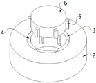
FIG. 2 is a perspective view of a portion of the quick release assembly of the present invention;
FIG. 3 is an enlarged view of the point A in FIG. 1 according to the present invention;
FIG. 4 is a schematic view of a cross-bar portion of the present invention;
fig. 5 is a rear view of a portion of the control cabinet of the present invention.
In the figure: 1. a host; 2. a bearing; 3. an inner ring; 4. a card slot; 5. clamping the strip; 6. connecting columns; 7. a control cabinet; 8. a screw; 9. a knob; 10. a first thread; 11. a first nut; 12. a second thread; 13. a second nut; 14. a cross bar; 15. a supporting sleeve; 16. rotating the sleeve; 17. a deflector rod; 18. a sleeve; 19. a take-up drum; 20. connecting ropes; 21. a spline; 22. a first splint; 23. a second splint; 24. a non-slip mat; 25. a display; 26. inserting slots; 27. a rod is inserted; 28. a top plate; 29. a clamping plate; 30. a bottom bar; 31. cleaning cotton; 32. a pressure lever; 33. a slide board.
Detailed Description
The technical solutions in the embodiments of the present invention will be clearly and completely described below with reference to the drawings in the embodiments of the present invention, and it is obvious that the described embodiments are only a part of the embodiments of the present invention, and not all of the embodiments. All other embodiments, which can be obtained by a person skilled in the art without making any creative effort based on the embodiments in the present invention, belong to the protection scope of the present invention.
In the description of the present invention, it should be noted that the terms "vertical", "upper", "lower", "horizontal", and the like indicate orientations or positional relationships based on the orientations or positional relationships shown in the drawings, which are only for convenience of description and simplification of the description, and do not indicate or imply that the device or element referred to must have a specific orientation, be constructed in a specific orientation, and operate, and thus, should not be construed as limiting the present invention.
In the description of the present invention, it should also be noted that, unless otherwise explicitly stated or limited, the terms "disposed," "mounted," "connected," and "connected" are to be construed broadly and may be, for example, fixedly connected, detachably connected, or integrally connected; can be mechanically or electrically connected; they may be connected directly or indirectly through intervening media, or they may be interconnected between two elements. The specific meanings of the above terms in the present invention can be understood according to specific situations by those of ordinary skill in the art.
Referring to fig. 1-5, a display device for processing remote sensing images convenient for splicing and positioning comprises a host 1, wherein the top of the host 1 is connected with a control cabinet 7 through a quick-release assembly, a screw 8 is rotatably arranged in the control cabinet 7, the tail end of the screw 8 extends to the outside of the control cabinet 7 and is fixedly connected with a knob 9, a first thread 10 is arranged on the left side of the outer wall of the screw 8, and a second thread 12 is arranged on the right side of the outer wall of the screw 8;
the outer wall of the first thread 10 is in threaded connection with a first nut 11, the outer wall of the second thread 12 is in threaded connection with a second nut 13, the tops of the first nut 11 and the second nut 13 are respectively fixedly provided with a first clamping plate 22 and a second clamping plate 23, the surfaces, opposite to the first clamping plate 22 and the second clamping plate 23, of the first clamping plate 22 are respectively fixedly provided with an anti-skid pad 24, and a display 25 is clamped between the first clamping plate 22 and the second clamping plate 23;
a top plate 28 is fixedly installed at the top of the display 25, slots 26 are formed in two sides of the interior of the display 25, inserting rods 27 are inserted into the slots 26, and the inserting rods 27 are fixedly installed at the top of the control cabinet 7;
further comprising:
a cleaning assembly for cleaning the surface of the display 25, and a control assembly for controlling the deformation of the cleaning assembly.
In this embodiment, the quick detach subassembly includes bearing 2 and spliced pole 6, the inner wall fixed mounting of bearing 2 has inner ring 3, draw-in groove 4 has evenly been seted up to inner ring 3's inner wall, the inner wall joint of draw-in groove 4 has card strip 5, the even fixed mounting of card strip 5 is on the outer wall of spliced pole 6, a switch board 7 for bearing display 25 is connected with host computer 1 through the quick detach subassembly, directly during the installation card strip 5 card of spliced pole 6 outer wall advance in the draw-in groove 4 of bearing 2 inner wall inner ring 3 can, directly lift up switch board 7 when taking off can, and because card strip 5 card advances in draw-in groove 4, so switch board 7 still can rotate through bearing 2, the direction of adjustment switch board 7 and display 25, the structure is simpler, the dismouting is more convenient.
In this embodiment, the inner wall of the slot 26 is fixedly provided with a damping pad for increasing the friction force between the insertion rod 27 and the slot 26, so that the display 25 has a certain resistance when moving relative to the insertion rod 27, and people can conveniently adjust the position of the display 25.
In this embodiment, the opening directions of the first thread 10 and the second thread 12 on the outer wall of the screw 8 are opposite, the screw 8 rotates to drive the first nut 11 and the second nut 13 to move in opposite directions through the first thread 10 and the second thread 12, which are formed on the outer wall of the screw and have opposite directions, and the first nut 11 and the second nut 13 move in opposite directions to enable the first clamping plate 22 and the second clamping plate 23 to approach or separate from each other.
In this embodiment, the cleaning assembly includes a bottom rod 30, cleaning cotton 31 and a pressure rod 32, the front and rear sides of the display 25 are provided with the clamping plates 29, the bottom rod 30 is fixedly installed on the outer wall of the clamping plate 29 on one side of the front surface of the display 25, the top of the bottom rod 30 is fixedly installed with the cleaning cotton 31, the top of the cleaning cotton 31 is fixedly installed with the pressure rod 32, the left and right sides of the pressure rod 32 are both slidably connected with sliding plates 33, and the sliding plates 33 are fixedly installed on the outer wall of the clamping plate 29;
the bottom of the pressure lever 32 is also fixedly connected with a connecting rope 20, the connecting rope 20 passes through the cleaning cotton 31 and the bottom lever 30 and extends to the inside of the control cabinet 7, when the connecting rope 20 is pulled, the pressure lever 32 presses the cleaning cotton 31 to deform the cleaning cotton 31, when the connecting rope 20 is received by the take-up drum 19, the connecting rope 20 can pull the pressure lever 32 to enable the pressure lever 32 to move downwards, the pressure lever 32 moves downwards to press the cleaning cotton 31, the cleaning cotton 31 is extruded to deform and bulge outwards, the bulged part contacts the display 25, at the moment, the display 25 is drawn in and out to clean the surface of the display 25, when connecting rope 20 and being rolled out, depression bar 32 and clearance cotton 31 have lost the pulling force of connecting rope 20, can be at the effect of clearance cotton 31 self elasticity under the reconversion, and the round trip deformation of clearance cotton 31 can also rely on the motion of self to vibrate the dust of its surface adhesion, needn't change often.
In the embodiment, the control assembly comprises a cross rod 14 and a take-up drum 19, the middle part of the screw 8 is cut off, the cross rod 14 is filled in the cut-off part, the sleeve 18 is sleeved on the outer wall of the cross rod 14, the take-up drums 19 are fixedly installed on the left side and the right side of the sleeve 18, and the connecting rope 20 is wound on the outer wall of the take-up drum 19;
the outer wall of the sleeve 18 is rotatably connected with a rotating sleeve 16, the bottom of the rotating sleeve 16 is slidably connected with a supporting sleeve 15, the supporting sleeve 15 is fixedly installed on the inner bottom wall of the control cabinet 7, a shifting rod 17 is further fixedly installed on the outer wall of the rotating sleeve 16, the tail end of the shifting rod 17 extends to the outside of the control cabinet 7, and a movable groove corresponding to the shifting rod 17 is further formed in the outer wall of the control cabinet 7.
In this embodiment, the outer wall of horizontal pole 14 is provided with spline 21, set up the flower trough corresponding with spline 21 on the inner wall of the receipts line section of thick bamboo 19 on sleeve 18 right side, stir driving lever 17 about and control sleeve 18 and receive line section of thick bamboo 19, when the flower trough of receiving line section of thick bamboo 19 inner wall and the spline 21 looks block of horizontal pole 14 outer wall, 8 rotations of screw rod can drive receipts line section of thick bamboo 19 rotatory, accomodate connecting rope 20 or exhibition connecting rope 20, when the flower trough of receiving line section of thick bamboo 19 inner wall and the spline 21 looks block of horizontal pole 14 outer wall, 8 rotations of screw rod can't drive receipts line section of thick bamboo 19 rotatoryly, control is got up more convenience.
The working principle and the using process of the invention are as follows:
the control cabinet 7 for bearing the display 25 is connected with the host 1 through the quick-release assembly, the clamping strip 5 on the outer wall of the connecting column 6 is directly clamped into the clamping groove 4 of the inner ring 3 on the inner wall of the bearing 2 during installation, the control cabinet 7 is directly lifted during removal, and the clamping strip 5 is clamped into the clamping groove 4, so that the control cabinet 7 can also rotate through the bearing 2, the directions of the control cabinet 7 and the display 25 are adjusted, the structure is simpler, and the disassembly and the assembly are more convenient;
the display 25 is clamped between the first clamping plate 22 and the second clamping plate 23, the first clamping plate 22 and the second clamping plate 23 can be close to or away from each other by screwing the screw 8 through the knob 9, specifically, the screw 8 rotates to drive the first nut 11 and the second nut 13 to move in opposite directions through the first thread 10 and the second thread 12 which are arranged on the outer wall of the screw and have opposite directions, and the first nut 11 and the second nut 13 move in opposite directions to enable the first clamping plate 22 and the second clamping plate 23 to be close to or away from each other;
when the first clamping plate 22 and the second clamping plate 23 are close to each other, the non-slip mat 24 can clamp the display 25 to fix the position of the display 25, and when the first clamping plate 22 and the second clamping plate 23 are far away from each other, the display 25 can be accommodated between the first clamping plate 22 and the second clamping plate 23, the display 25 can also be pulled out for convenient viewing, and the display 25 can be directly pulled out from the insertion rod 27 for replacement;
the screw 8 rotates and simultaneously drives the cross rod 14 to rotate, the poking rod 17 is poked leftwards and rightwards to move the sleeve 18 and the take-up drum 19 leftwards and rightwards, when the flower groove in the inner wall of the take-up drum 19 is clamped with the spline 21 on the outer wall of the cross rod 14, the screw 8 rotates to drive the take-up drum 19 to rotate and store the connecting rope 20 or unfold the connecting rope 20, and when the flower groove in the inner wall of the take-up drum 19 is not clamped with the spline 21 on the outer wall of the cross rod 14, the screw 8 cannot rotate to drive the take-up drum 19 to rotate, so that the control is more convenient;
when connecting rope 20 is accomodate by receiving a line section of thick bamboo 19, connecting rope 20 can stimulate depression bar 32 and make depression bar 32 downstream, depression bar 32 downstream moves the pressure and moves clearance cotton 31, clearance cotton 31 can be out of shape and protruding outwards by the extrusion, bellied part contact display 25, it takes out display 25 alright to clear up display 25's surface to take out again this moment, when connecting rope 20 is shown, depression bar 32 and clearance cotton 31 have lost the pulling force of connecting rope 20, can be in clearance cotton 31 self elastic force effect under the reconversion, the round trip deformation of clearance cotton 31 can also rely on the dust of its surface adhesion of motion shock of self, needn't change often.
Although embodiments of the present invention have been shown and described, it will be appreciated by those skilled in the art that changes, modifications, substitutions and alterations can be made in these embodiments without departing from the principles and spirit of the invention, the scope of which is defined in the appended claims and their equivalents.
Claims (4)
1. The utility model provides a remote sensing image handles and uses display device convenient to concatenation location, includes host computer (1), its characterized in that: the top of the host (1) is connected with a control cabinet (7) through a quick-release assembly, a screw rod (8) is rotatably arranged inside the control cabinet (7), the tail end of the screw rod (8) extends to the outside of the control cabinet (7) and is fixedly connected with a knob (9), a first thread (10) is formed in the left side of the outer wall of the screw rod (8), and a second thread (12) is formed in the right side of the outer wall of the screw rod (8);
the outer wall of the first thread (10) is in threaded connection with a first nut (11), the outer wall of the second thread (12) is in threaded connection with a second nut (13), the tops of the first nut (11) and the second nut (13) are respectively fixedly provided with a first clamping plate (22) and a second clamping plate (23), one surfaces, opposite to the first clamping plate (22) and the second clamping plate (23), of the first clamping plate (22) are respectively fixedly provided with an anti-skid pad (24), and a display (25) is clamped between the first clamping plate (22) and the second clamping plate (23);
a top plate (28) is fixedly mounted at the top of the display (25), slots (26) are formed in two sides of the interior of the display (25), inserting rods (27) are inserted into the slots (26), and the inserting rods (27) are fixedly mounted at the top of the control cabinet (7);
further comprising:
a cleaning component for cleaning the surface of the display (25), and a control component for controlling the deformation of the cleaning component;
the cleaning assembly comprises a bottom rod (30), cleaning cotton (31) and a pressure rod (32), clamping plates (29) are arranged on the front side and the rear side of the display (25), the bottom rod (30) is fixedly installed on the outer wall of the clamping plate (29) on one side of the front face of the display (25), the cleaning cotton (31) is fixedly installed at the top of the bottom rod (30), the pressure rod (32) is fixedly installed at the top of the cleaning cotton (31), sliding plates (33) are connected to the left side and the right side of the pressure rod (32) in a sliding mode, and the sliding plates (33) are fixedly installed on the outer wall of the clamping plates (29);
the bottom of the pressure lever (32) is also fixedly connected with a connecting rope (20), the connecting rope (20) penetrates through the cleaning cotton (31) and the bottom rod (30) and extends into the control cabinet (7), and when the connecting rope (20) is pulled, the pressure lever (32) presses the cleaning cotton (31) to enable the cleaning cotton (31) to deform;
the control assembly comprises a cross rod (14) and a wire collecting barrel (19), the middle of the screw rod (8) is cut off, the cross rod (14) is arranged at the cut-off position in a filling mode, a sleeve (18) is sleeved on the outer wall of the cross rod (14), the wire collecting barrel (19) is fixedly arranged on the left side and the right side of the sleeve (18), and the connecting rope (20) is wound on the outer wall of the wire collecting barrel (19);
the outer wall of the sleeve (18) is rotatably connected with a rotating sleeve (16), the bottom of the rotating sleeve (16) is connected with a supporting sleeve (15) in a sliding mode, the supporting sleeve (15) is fixedly installed on the inner bottom wall of the control cabinet (7), the outer wall of the rotating sleeve (16) is further fixedly provided with a shifting rod (17), the tail end of the shifting rod (17) extends to the outer portion of the control cabinet (7), and the outer wall of the control cabinet (7) is further provided with a movable groove corresponding to the shifting rod (17);
the outer wall of the cross rod (14) is provided with a spline (21), and the inner wall of the take-up drum (19) on the right side of the sleeve (18) is provided with a flower groove corresponding to the spline (21).
2. The display device for processing remote sensing images convenient for splicing and positioning according to claim 1, wherein: the quick detach subassembly includes bearing (2) and spliced pole (6), the inner wall fixed mounting of bearing (2) has inner ring (3), draw-in groove (4) have evenly been seted up to the inner wall of inner ring (3), the inner wall joint of draw-in groove (4) has card strip (5), the even fixed mounting of card strip (5) is on the outer wall of spliced pole (6).
3. The display device for processing remote sensing images convenient for splicing and positioning according to claim 1, wherein: and damping pads for increasing the friction force between the inserted rod (27) and the slot (26) are fixedly arranged on the inner wall of the slot (26).
4. The display device for processing remote sensing images convenient for splicing and positioning according to claim 3, wherein: the first thread (10) and the second thread (12) are arranged on the outer wall of the screw rod (8) in opposite directions.
Priority Applications (1)
| Application Number | Priority Date | Filing Date | Title |
|---|---|---|---|
| CN202110105826.4A CN112879747B (en) | 2021-01-26 | 2021-01-26 | Remote sensing image processing display device convenient for splicing and positioning |
Applications Claiming Priority (1)
| Application Number | Priority Date | Filing Date | Title |
|---|---|---|---|
| CN202110105826.4A CN112879747B (en) | 2021-01-26 | 2021-01-26 | Remote sensing image processing display device convenient for splicing and positioning |
Publications (2)
| Publication Number | Publication Date |
|---|---|
| CN112879747A CN112879747A (en) | 2021-06-01 |
| CN112879747B true CN112879747B (en) | 2022-07-22 |
Family
ID=76052108
Family Applications (1)
| Application Number | Title | Priority Date | Filing Date |
|---|---|---|---|
| CN202110105826.4A Expired - Fee Related CN112879747B (en) | 2021-01-26 | 2021-01-26 | Remote sensing image processing display device convenient for splicing and positioning |
Country Status (1)
| Country | Link |
|---|---|
| CN (1) | CN112879747B (en) |
Citations (7)
| Publication number | Priority date | Publication date | Assignee | Title |
|---|---|---|---|---|
| KR100788784B1 (en) * | 2007-10-25 | 2008-01-02 | 문엔지니어링 (주) | Multimedia display board |
| WO2012109638A1 (en) * | 2011-02-11 | 2012-08-16 | Ergotron, Inc. | Bifocal display positioning apparatus and method |
| CN206411556U (en) * | 2016-12-16 | 2017-08-15 | 杨道宇 | A kind of computer for being easy to clear up display |
| CN209886239U (en) * | 2019-04-03 | 2020-01-03 | 訚战能 | Medical image film watching device |
| CN111862791A (en) * | 2020-07-16 | 2020-10-30 | 湖北航天保华科技股份有限公司 | Industrial display based on thing networking remote control |
| CN211956601U (en) * | 2020-05-28 | 2020-11-17 | 联通沃悦读科技文化有限公司 | Big data face monitoring device |
| CN112259003A (en) * | 2020-10-22 | 2021-01-22 | 湖南合利来智慧显示科技有限公司 | High-definition full-color LED display screen used for conference system and use method thereof |
Family Cites Families (13)
| Publication number | Priority date | Publication date | Assignee | Title |
|---|---|---|---|---|
| US7666262B2 (en) * | 2005-11-21 | 2010-02-23 | 1570 Cinema Services, Llc | Process for cleaning large format or giant screen movie screens |
| US20130105646A1 (en) * | 2011-10-31 | 2013-05-02 | Timothy Owens | Space-Saving Flat Screen Television Stand |
| CN103851314A (en) * | 2012-12-07 | 2014-06-11 | 富泰华工业(深圳)有限公司 | Rotating mechanism and display device with same |
| CN208368033U (en) * | 2018-04-14 | 2019-01-11 | 东莞市科学技术博物馆 | A kind of electronic information display device being moved easily and clean screen |
| CN208341013U (en) * | 2018-05-06 | 2019-01-08 | 江苏光明环境设备有限公司 | Suspension apparatus is used in a kind of spraying of screw thread tube outer surface |
| CN208703446U (en) * | 2018-07-03 | 2019-04-05 | 唐山市安道信息咨询有限公司 | A kind of fixing protector for light-emitting diode display |
| CN208735166U (en) * | 2018-09-12 | 2019-04-12 | 杭州微法软件技术有限公司 | A kind of Computer Network Project exploitation displaying device |
| CN210166677U (en) * | 2018-12-07 | 2020-03-20 | 西安居正知识产权运营管理有限公司 | Computer display dust cover device |
| CN209199524U (en) * | 2019-01-10 | 2019-08-02 | 深圳市聚美通用科技有限公司 | A kind of liquid crystal display dust guard |
| CN211087775U (en) * | 2019-12-28 | 2020-07-24 | 重庆帝安科技有限公司 | Novel transparent display screen |
| CN211783438U (en) * | 2020-03-31 | 2020-10-27 | 郑州升达经贸管理学院 | Display device for remote sensing image processing convenient to concatenation location |
| CN212338650U (en) * | 2020-04-10 | 2021-01-12 | 梁康泉 | Multifunctional household appliance base |
| CN112197122A (en) * | 2020-10-19 | 2021-01-08 | 江西鑫彩晨光电科技有限公司 | Anti-shock and anti-falling type LED display screen |
-
2021
- 2021-01-26 CN CN202110105826.4A patent/CN112879747B/en not_active Expired - Fee Related
Patent Citations (7)
| Publication number | Priority date | Publication date | Assignee | Title |
|---|---|---|---|---|
| KR100788784B1 (en) * | 2007-10-25 | 2008-01-02 | 문엔지니어링 (주) | Multimedia display board |
| WO2012109638A1 (en) * | 2011-02-11 | 2012-08-16 | Ergotron, Inc. | Bifocal display positioning apparatus and method |
| CN206411556U (en) * | 2016-12-16 | 2017-08-15 | 杨道宇 | A kind of computer for being easy to clear up display |
| CN209886239U (en) * | 2019-04-03 | 2020-01-03 | 訚战能 | Medical image film watching device |
| CN211956601U (en) * | 2020-05-28 | 2020-11-17 | 联通沃悦读科技文化有限公司 | Big data face monitoring device |
| CN111862791A (en) * | 2020-07-16 | 2020-10-30 | 湖北航天保华科技股份有限公司 | Industrial display based on thing networking remote control |
| CN112259003A (en) * | 2020-10-22 | 2021-01-22 | 湖南合利来智慧显示科技有限公司 | High-definition full-color LED display screen used for conference system and use method thereof |
Also Published As
| Publication number | Publication date |
|---|---|
| CN112879747A (en) | 2021-06-01 |
Similar Documents
| Publication | Publication Date | Title |
|---|---|---|
| CN109862230B (en) | Camera assembly, mobile terminal and control method of camera assembly | |
| CN212840392U (en) | Touch liquid crystal display convenient to installation | |
| CN112879747B (en) | Remote sensing image processing display device convenient for splicing and positioning | |
| CN105046850A (en) | POS machine detection device | |
| CN109541880B (en) | Anti-falling projector and using method thereof | |
| CN213715674U (en) | Lens protection mechanism for projecting apparatus | |
| CN217361057U (en) | Brightness-adjustable liquid crystal display screen | |
| CN212373953U (en) | Concatenation formula camera tray | |
| CN214070007U (en) | High definition surveillance camera machine heat dissipation defogging structure | |
| CN209752425U (en) | Dustproof mechanism of adjustable load cabinet of hoisting apparatus | |
| CN113077687A (en) | Photographic view finding demonstration teaching appliance | |
| CN217482403U (en) | Movable sliding rail screen | |
| CN217959247U (en) | Metal goods shelves convenient to installation | |
| CN214425586U (en) | Aluminum product image acquisition device | |
| CN219120205U (en) | Video conference terminal bracket for multiple display screens | |
| CN213685915U (en) | Digital high-definition camera | |
| CN215219658U (en) | Touch display convenient to installation | |
| CN220798411U (en) | Monitoring device with auxiliary mounting structure | |
| CN219577603U (en) | Buckle type structure for LED display screen | |
| CN210381125U (en) | Building engineering management video acquisition equipment | |
| CN220749527U (en) | Electric control rocker arm with neat circuit | |
| CN218254849U (en) | Smelting tool for assembling display screens of different specifications | |
| CN216817704U (en) | Modular combined type news fusion media work display equipment | |
| CN220061325U (en) | Propaganda screen with camera | |
| CN216580380U (en) | Detection device for detecting dangerous driving of forklift driver |
Legal Events
| Date | Code | Title | Description |
|---|---|---|---|
| PB01 | Publication | ||
| PB01 | Publication | ||
| SE01 | Entry into force of request for substantive examination | ||
| SE01 | Entry into force of request for substantive examination | ||
| GR01 | Patent grant | ||
| GR01 | Patent grant | ||
| CF01 | Termination of patent right due to non-payment of annual fee |
Granted publication date: 20220722 |
|
| CF01 | Termination of patent right due to non-payment of annual fee |