Melt chute of alkali recovery boiler
Technical Field
The invention belongs to the technical field of alkali recovery boilers, and particularly relates to a melt chute of an alkali recovery boiler.
Background
When the alkali recovery boiler operates, the molten salt in a molten state at the bottom of the boiler has a temperature of about 900 ℃, continuously flows out through the melt chute, and enters the dissolving tank at the lower part of the chute for dissolving. And demineralized water at about 40 ℃ flows through the jacket of the melt chute to cool the melt chute.
The melt chute is key equipment of an alkali recovery boiler in a pulp mill, and needs to be replaced once the melt chute is damaged and leaked, the alkali furnace must be stopped when the melt chute is replaced, and the loss caused by the stop is far greater than the value of the melt chute equipment. The following problems are present in the melt chutes which are commonly found on the market:
1. the inlet tube is located melt chute lower part, and the outlet pipe is located melt chute upper portion, and the pipeline is arranged complicacy, dismantles the melt chute difficulty.
2. The leakage can be caused after about 3-6 months of most of the traditional Chinese medicine.
Disclosure of Invention
The invention aims to overcome the defects of the prior art and provide the melt chute of the alkali recovery boiler, which has the advantages of simple pipeline arrangement and convenient disassembly and can effectively prolong the service life of the melt chute.
In order to achieve the purpose, the invention adopts the following technical scheme:
the utility model provides an alkali recovery boiler melt chute, its cell body is hollow jacket structure, includes upper portion cover and lower part cover, be equipped with the baffle in the upper portion cover with the upper portion cover is separated into water inlet space and play water space, the water inlet space external inlet tube, play water space external outlet pipe, water inlet space and lower part cover intercommunication, lower part cover and play water space intercommunication.
Furthermore, a guide plate is arranged in the lower jacket, and the guide plate is arranged along the length direction of the lower jacket 2, so that cooling water flows back and forth in the lower jacket after entering the lower jacket and then flows out of the lower jacket.
Furthermore, the lower jacket is of an obliquely arranged U-shaped long groove structure and comprises a lower outer jacket and a lower inner jacket, the tail ends and two upper end faces of the lower outer jacket and the lower inner jacket are sealed through an upper jacket connecting pipe and a lower jacket connecting pipe, and the upper jacket connecting pipe and the lower jacket connecting pipe are composed of two straight pipe sections and a U-shaped pipe section;
the upper jacket is of an arc-shaped structure, is arranged right above the front end of the upper and lower jacket connecting pipe and forms a cylindrical melt inlet together with the front end of the lower jacket, the upper jacket comprises an upper outer jacket and an upper inner jacket, the tail ends of the upper outer jacket and the upper inner jacket are sealed by sealing plates, and the head ends of the upper jacket and the lower jacket are sealed by annular upper and lower jacket connecting pipe rings;
the upper part jacket is internally provided with two clapboards along the length direction, the two clapboards, the upper part outer jacket, the upper part inner jacket, the inner sides of the upper and lower jacket connecting pipe rings and the sealing plates define the water inlet space, the sealing plates are provided with water inlets corresponding to the water inlet space, the water inlets are communicated with the water inlet pipe,
the partition plate, the upper outer jacket, the upper inner jacket, the upper end surface of the upper jacket connecting pipe, the lower jacket connecting pipe and the sealing plate define the water outlet space, two water outlet spaces are arranged, a water outlet is arranged on the sealing plate corresponding to the water outlet space, and the water outlet is communicated with the water outlet pipe;
a first through hole is formed in the position, corresponding to the water inlet space, of the upper and lower jacket connecting pipe rings, and a second through hole is formed in the position, corresponding to the lower jacket, of the upper jacket connecting pipe ring;
and third through holes are formed in the positions, corresponding to the lower jacket, of the two sides of the U-shaped pipe section of the upper and lower jacket connecting pipe, and fourth through holes are formed in the positions, corresponding to the water outlet space in the upper jacket, of the two straight pipe sections.
Furthermore, four guide plates are arranged in the lower jacket, so that cooling water flowing out of the second through hole on the upper jacket connecting pipe ring and the lower jacket connecting pipe ring enters the lower jacket and then respectively flows back and forth on two sides of the lower jacket and then enters the third through hole of the upper jacket connecting pipe and the lower jacket connecting pipe.
Furthermore, two sides of the bottom of the lower jacket are respectively provided with a first guide plate along the length direction, one end of each first guide plate is connected with and not communicated with the upper jacket connecting pipe ring and the lower jacket connecting pipe ring, the other end of each first guide plate extends to the tail end of the lower jacket and keeps a certain gap with the U-shaped pipe section of the upper jacket connecting pipe and the lower jacket connecting pipe, and the position of a second through hole on the upper jacket connecting pipe ring and the lower jacket connecting pipe ring corresponds to a space defined by the two first guide plates, the lower outer jacket and the lower inner jacket, so that cooling water flowing out of the upper jacket connecting pipe ring and the lower jacket connecting pipe ring enters the space and then flows;
and a second guide plate is arranged above each first guide plate, one end of each second guide plate extends to the upper and lower jacket connecting pipe rings and keeps a certain gap, and the other end of each second guide plate is not communicated with the inner wall of the lower jacket and is positioned below the position of the third through hole.
Furthermore, the second guide plate is in two-section type and is connected in a folding line mode, one section of the second guide plate is parallel to the first guide plate, one end of the second guide plate is close to the upper jacket connecting pipe ring and the lower jacket connecting pipe ring, a certain gap is reserved between the upper jacket connecting pipe ring and the lower jacket connecting pipe ring, and the other section of the second guide plate is not communicated with the inner wall of the lower jacket and is located between the tail end of the first.
Still further, a support structure extends downwardly below the sealing plate.
Furthermore, the tank body is provided with supporting legs, an angle steel connecting piece is arranged on the outer side of the upper and lower jacket connecting pipe, the water inlet pipe and the water outlet pipe are arranged on the mounting plate, and the mounting plate, the angle steel connecting piece and the supporting legs are welded together.
Furthermore, the tank body is made of a steel structure.
The invention has the beneficial effects that:
1. the special guide plate and partition plate structure are arranged in the jacket of the melt chute, cooling water flows between the inner jacket and the outer jacket of the melt chute along the direction of an arrow when the chute works, the cooling water is fully deflected, the temperature of all positions of the inner jacket of the melt chute is uniformly distributed, the thermal stress is small, the service life of the melt chute can be effectively prolonged, and the service life of the chute can reach more than 12 months.
2. The cooling water inlet and outlet pipes of the melt chute are positioned at the upper part of the chute, the pipeline arrangement is simple, and the melt chute is simple and convenient to disassemble.
Drawings
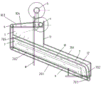
FIG. 1 is a perspective view of one of the present chutes;
FIG. 2 is a perspective view of one of the chutes of the present invention;
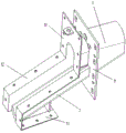
FIG. 3 is a perspective view of the spout of the present invention with the water inlet and outlet tubes removed from one perspective;
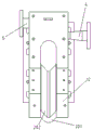
FIG. 4 is a front elevational view of the chute of the present invention;
FIG. 5 is a top plan view of the chute of the present invention;
FIG. 6 is a schematic view showing the internal structure of a jacket at a melt inlet of the chute according to the present invention;
FIG. 7 is a cross-sectional view of the interior of the jacket at the melt inlet of the chute of the present invention;
FIG. 8 is a schematic view showing the structure of the upper and lower jacket connecting pipe rings of the chute of the present invention;
FIG. 9 is a schematic view of the inlet pipe portion of the chute of the present invention;
FIG. 10 is a schematic view of the outlet pipe portion of the chute of the present invention;
FIG. 11 is a schematic view showing the structure of a connecting pipe for upper and lower jackets of the chute according to the present invention;
wherein: 1. an upper jacket; 101. a water inlet space; 102. a water outlet space; 103. an upper outer jacket; 104. an upper inner jacket; 105. a water inlet; 106. a water outlet; 2. a lower jacket; 201. a lower outer jacket; 202. a lower inner jacket; 3. a partition plate; 4. a water inlet pipe; 5. a water outlet pipe; 6. The upper and lower jackets are connected with the pipe ring; 601. a first through hole; 602. a second through hole; 7. an upper jacket connecting pipe and a lower jacket connecting pipe; 701. a straight pipe section; 702. a U-shaped tube section; 703. a third through hole; 704. a fourth via hole; 8. closing the plate; 9. a first baffle; 10. a second baffle; 11. supporting legs; 12. an angle steel connecting piece; 13. and (7) mounting the plate.
Detailed Description
To better illustrate the objects, aspects and advantages of the present invention, the present invention will be further described with reference to specific embodiments. This invention may be embodied in many different forms and should not be construed as limited to the embodiments set forth herein. Rather, these embodiments are provided so that this disclosure will be thorough and complete and will fully convey the concept of the invention to those skilled in the art, and the present invention will only be defined by the appended claims.
As shown in figures 1-11, the trough body of the alkali recovery boiler melt chute is of a hollow jacket structure and comprises an upper jacket 1 and a lower jacket 2. The slot body is made of a steel structure, and is selected from one of S30408(304), S30403(304L), S31608(316), S310603(316L), S31008(310S), S22053(2205), Q245R, Q345R and 20 #. The thickness of the inner jacket steel plate and the outer jacket steel plate can be selected from 6mm, 8mm and 10 mm. The outer diameter of the connecting pipe between the inner clamping sleeve and the outer clamping sleeve can be selected from 28mm, 30mm, 32mm, 34mm and 36 mm. The connection of all parts of the chute is a welded structure.
A partition plate 3 is arranged in the upper jacket 1 to divide the upper jacket 1 into a water inlet space 101 and a water outlet space 102, the water inlet space 101 is externally connected with a water inlet pipe 4, the water outlet space 102 is externally connected with a water outlet pipe 5, the water inlet space 101 is communicated with the lower jacket 2, and the lower jacket 2 is communicated with the water outlet space 102. The cooling water inlet pipe 4 and the cooling water outlet pipe 5 of the melt chute are both positioned at the upper part of the chute, the pipeline arrangement is simple, and the melt chute is simple and convenient to disassemble.
As one example, the lower jacket 2 is an inclined U-shaped long groove structure, and includes a lower outer jacket 201 and a lower inner jacket 202, and the tail ends and two upper end faces of the lower outer jacket 201 and the lower inner jacket 202 are sealed by an upper jacket connecting pipe 7 and a lower jacket connecting pipe 7. The upper and lower jacket connecting pipe 7 is constructed as shown in fig. 11, the upper and lower jacket connecting pipe 7 is composed of two straight pipe sections 701 and a U-shaped pipe section 702, the two straight pipe sections 701 are located at the two upper end faces of the lower outer jacket 201 and the lower inner jacket 202 and seal them, and the U-shaped pipe section 702 is located at the rear ends of the lower outer jacket 201 and the lower inner jacket 202 and seal them.
The upper jacket 1 is of an arc-shaped structure and is arranged right above the front end of the upper and lower jacket connecting pipes 7, the front ends of the upper jacket 1, the upper and lower jacket connecting pipes 7 and the front end of the lower jacket 2 jointly enclose a cylindrical melt inlet, and high-temperature melt enters the chute from the melt inlet to exchange heat with cooling water in the chute jacket.
The upper jacket 1 comprises an upper outer jacket 103 and an upper inner jacket 104, the rear ends of the upper outer jacket 103 and the upper inner jacket 104 are sealed by a sealing plate 8, and the sealing plate 8 functions to form a closed space with the upper outer jacket 103 and the upper inner jacket 104 so that cooling water flows in the space.
A support structure extending downwards below the closing plate 8 plays a role in supporting the chute. The head ends of the upper jacket 1 and the lower jacket 2 are sealed by the annular upper and lower jacket connecting pipe rings 6.
Two partition plates 3 are arranged in the upper jacket 1 along the length direction, and the partition plates 3 are used for separating the inlet water and the outlet water of the cooling water. The two partition plates 3, the upper outer jacket 103, the upper inner jacket 104, the inner sides of the upper and lower jacket connecting pipe rings 6 and the sealing plate 8 define a water inlet space 101, a water inlet 105 is arranged on the sealing plate 8 corresponding to the water inlet space 101, and the water inlet 105 is communicated with the water inlet pipe 4. The partition plate 3, the upper outer jacket 103, the upper inner jacket 104, the upper end surface of the upper and lower jacket connecting pipe 7 and the sealing plate 8 enclose a water outlet space 102, two water outlet spaces 102 are arranged, a water outlet 106 is arranged on the sealing plate 8 corresponding to the water outlet space 102, and the water outlet 106 is communicated with the water outlet pipe 5.
The upper and lower jacket connecting pipe rings 6 are structured as shown in fig. 8, and the upper and lower jacket connecting pipe rings 6 are provided with a first through hole 601 at a position corresponding to the water inlet space 101 and a second through hole 602 at a position corresponding to the lower jacket 2.
The structure of the upper and lower jacket connecting pipe 7 is shown in fig. 11, both sides of a U-shaped pipe section 702 of the upper and lower jacket connecting pipe 7 are provided with third through holes 703 corresponding to the positions of the lower jacket 2, and both straight pipe sections 701 are provided with fourth through holes 704 corresponding to the positions of the water outlet space 102 in the upper jacket 1.
Furthermore, a guide plate is arranged in the lower jacket 2, and the guide plate is arranged along the length direction of the lower jacket 2, so that cooling water enters the lower jacket 2, flows back and forth in the lower jacket 2 and then flows out of the lower jacket 2.
As an example, four baffles are provided in the lower jacket 2 so that the cooling water flowing out of the second through holes 602 of the upper and lower jacket connecting tube rings 6 enters the lower jacket 2, flows back and forth on both sides of the lower jacket 2, and enters the third through holes 703 of the upper and lower jacket connecting tubes 7.
Specifically, two sides of the bottom of the lower jacket 2 are respectively provided with a first guide plate 9 along the length direction, one end of each first guide plate 9 is connected with the upper jacket connecting pipe ring 6 and the lower jacket connecting pipe ring 6 and is not communicated, the other end of each first guide plate 9 extends to the tail end of the lower jacket 2 and is kept with the U-shaped pipe section 702 of the upper jacket connecting pipe 7 and the lower jacket connecting pipe ring 7 to form a certain gap, and the positions of the second through holes 602 in the upper jacket connecting pipe ring 6 and the lower jacket connecting pipe ring 6 correspond to a space defined by the two first guide plates 9, the lower outer jacket 201 and the lower inner jacket 202, so that cooling water flowing out of the upper jacket connecting pipe.
A second guide plate 10 is arranged above each first guide plate 9, one end of each second guide plate 10 extends to the upper and lower jacket connecting pipe rings 6 and keeps a certain gap, and the other end is not communicated with the inner wall of the lower jacket 2 and is positioned below the position of the third through hole 703.
Furthermore, the second guide plate 10 is two-sectioned and connected by a broken line, wherein one section is parallel to the first guide plate 9, one end of the second guide plate is close to the upper and lower jacket connecting pipe rings 6, and a certain gap is reserved, and the other section is not connected with the inner wall of the lower jacket 2 and is located between the end of the first guide plate 9 and the third through hole 703. The second guide plate 10 divides the space above the first guide plate 9 into two parts, the first guide plate 9 and the second guide plate 10 divide each side of the lower jacket 2 into three parts, and the cooling water flows into the upper and lower jacket connecting pipes 7 from the third through holes 703 after S-shaped deflection.
Furthermore, the trough body is provided with supporting legs 11, an angle steel connecting piece 12 is arranged on the outer side of the upper and lower jacket connecting pipe 7, the water inlet pipe 4 and the water outlet pipe 5 are arranged on a mounting plate 13, and the mounting plate 13, the angle steel connecting piece 12 and the supporting legs 11 are welded together.
When the melt chute works, cooling water flows between the inner sleeve and the outer sleeve of the melt chute along the direction shown by an arrow, the cooling water is fully deflected, the temperature of all the inner sleeves of the melt chute is uniformly distributed, the thermal stress is small, the service life of the melt chute can be effectively prolonged, and the service life of the melt chute can reach more than 12 months.
It should be understood that the above examples are only for clarity of illustration and are not intended to limit the embodiments. Other variations and modifications will be apparent to persons skilled in the art in light of the above description. And are neither required nor exhaustive of all embodiments. And obvious variations or modifications therefrom are within the scope of the invention.