CN112840820B - Auxiliary assembly for flower cultivation - Google Patents
Auxiliary assembly for flower cultivation Download PDFInfo
- Publication number
- CN112840820B CN112840820B CN202011627930.1A CN202011627930A CN112840820B CN 112840820 B CN112840820 B CN 112840820B CN 202011627930 A CN202011627930 A CN 202011627930A CN 112840820 B CN112840820 B CN 112840820B
- Authority
- CN
- China
- Prior art keywords
- rotating shaft
- bevel gear
- assembly
- wheel
- transmission
- Prior art date
- Legal status (The legal status is an assumption and is not a legal conclusion. Google has not performed a legal analysis and makes no representation as to the accuracy of the status listed.)
- Active
Links
Images


Classifications
-
- A—HUMAN NECESSITIES
- A01—AGRICULTURE; FORESTRY; ANIMAL HUSBANDRY; HUNTING; TRAPPING; FISHING
- A01C—PLANTING; SOWING; FERTILISING
- A01C17/00—Fertilisers or seeders with centrifugal wheels
- A01C17/001—Centrifugal throwing devices with a vertical axis
-
- Y—GENERAL TAGGING OF NEW TECHNOLOGICAL DEVELOPMENTS; GENERAL TAGGING OF CROSS-SECTIONAL TECHNOLOGIES SPANNING OVER SEVERAL SECTIONS OF THE IPC; TECHNICAL SUBJECTS COVERED BY FORMER USPC CROSS-REFERENCE ART COLLECTIONS [XRACs] AND DIGESTS
- Y02—TECHNOLOGIES OR APPLICATIONS FOR MITIGATION OR ADAPTATION AGAINST CLIMATE CHANGE
- Y02P—CLIMATE CHANGE MITIGATION TECHNOLOGIES IN THE PRODUCTION OR PROCESSING OF GOODS
- Y02P60/00—Technologies relating to agriculture, livestock or agroalimentary industries
- Y02P60/20—Reduction of greenhouse gas [GHG] emissions in agriculture, e.g. CO2
- Y02P60/21—Dinitrogen oxide [N2O], e.g. using aquaponics, hydroponics or efficiency measures
Abstract
The invention relates to the technical field of flower fertilizer application, and relates to auxiliary equipment for flower cultivation. In particular to flower fertilizer spraying equipment for flower cultivation; the equipment takes the rolling generated when the wheels advance as power to drive a coaxial first transmission wheel to rotate; the first transmission wheel acts on the lifting component through the transmission component to enable the lifting screw rod to move up and down; the lifting screw rod acts with a blanking assembly based on a lever principle to intermittently plug the outlet of the relay cylinder by the baffle plate, so that intermittent blanking of the relay cylinder is realized, and the blanking is carried out in the fertilizing disc; the first rotating shaft also rotates the third rotating shaft through the action of the transmission wheel set and the second transmission belt; the worm at the left end of the third rotating shaft also rotates immediately and drives the worm wheel to drive the fourth rotating shaft to rotate, so that the arc-shaped blade rotates in the fertilizing disc; the flower fertilizer is acted on the fertilizing disc by the arc-shaped blades to generate centrifugal motion and is thrown out from the discharging nozzle; along with the advance of equipment, need not to set up electrical equipment such as motor, can realize applying the flower fertilizer to the flowers of both sides.
Description
Technical Field
The invention relates to the technical field of flower fertilizer application, and relates to auxiliary equipment for flower cultivation. In particular to flower fertilizer applying and sprinkling equipment for flower cultivation.
Background
Flowers, herbaceous plants with ornamental value, are a collective name of plants for depicting appreciation, are pleased with yang and resistant to cold, have short branches with reproductive function, and are of many kinds. Typically, flowers, on a short axis of limited growth, bear calyx, petals and stamens and pistils that produce germ cells.
The flower is composed of corolla, calyx, receptacle and stamen, and has various colors, various growth, and fragrance or no fragrance.
Flowers have two meanings, namely broad sense and narrow sense: flowers in the narrow sense refer to herbaceous plants with ornamental value, such as impatiens balsamina, chrysanthemum, scarlet sage, cockscomb and the like; the flowers in a broad sense comprise herbaceous or woody ground cover plants, flowers and shrubs, flowering trees, bonsais and the like besides the herbaceous plants with ornamental value, such as the ground cover plants of lilyturf roots, sedums, bushy happiness, etc., and trees, flowers and shrubs of plum blossom, peach blossom, chinese rose, camellia, etc.
In addition, tall trees and shrubs distributed in southern areas are transplanted to northern cold areas and can only be used as greenhouse potted plants for appreciation, and white orchid, indian rubber trees, palm plants and the like are also listed in the broad flowers.
In modern society, people often plant, purchase, and wear flowers in various ways because of their pleasant appearance and fragrance. Flowers are used throughout the world in a wide variety of activities and situations throughout the life of a person.
Nowadays, flower cultivation is scaled and industrialized, many flower growers choose a mode similar to that of vegetable growers, a greenhouse is used as a carrier, a left area and a right area are divided in the greenhouse for planting and growing flowers, and a middle passage is reserved in the greenhouse and is used as a walking channel for people to go in and out conveniently.
The flower fertilizer is one of the material bases for flower growth, and the flower fertilizer provides one or more nutrient elements essential for plant or improves soil property and soil fertility.
The application of the flower fertilizer needs to be controlled timely and properly, the season and time need to be controlled, and the principle of 'frequently applying thin fertilizer', namely 'eating less and eating more meals', needs to be controlled.
However, the existing flower fertilizer application is carried out by adopting a manual spraying mode, and the flower fertilizer needs to be prepared in advance manually and then is manually sprayed; for large-scale production, the method is implemented according to the principle of 'thin fertilizer application frequently', the workload of manpower is large, and the production efficiency cannot be guaranteed.
Therefore, the inventors have devised an auxiliary device for flower cultivation to solve the above problems.
Disclosure of Invention
Technical problem to be solved
The invention aims to overcome the defects in the prior art and provide an auxiliary device for flower cultivation.
(II) technical scheme
Auxiliary equipment for cultivating flowers comprises a vehicle body assembly, a transmission assembly, a lifting assembly, a blanking assembly and a fertilizing assembly;
the vehicle body component comprises a vehicle plate, a wheel carrier, wheels, a push handle, a fixing frame, a flower fertilizer box, a feeding pipe, a relay cylinder and a receiving hopper; the left side of the vehicle plate is connected with a push handle, and the bottom of the vehicle plate is connected with wheels through a wheel carrier; the left end of the vehicle plate is connected with a fixing frame, the top of the fixing frame is connected with a plurality of flower fertilizer boxes, and the bottoms of the flower fertilizer boxes are communicated with the top of the relay cylinder through a blanking pipe;
the right part of the vehicle plate is provided with a lifting assembly, and the lifting assembly is connected with the wheels through a transmission assembly; a blanking assembly is arranged at the bottom of the relay cylinder and matched with the lifting assembly; the vehicle plate is also provided with a fertilizing assembly, and the fertilizing assembly is also matched with the transmission assembly; the receiving hopper is positioned below the relay cylinder, and the bottom end of the receiving hopper penetrates through the vehicle plate and extends into the fertilizing assembly.
Furthermore, the transmission assembly comprises a first transmission wheel, a first transmission belt, a second transmission wheel, a first bevel gear, a second bevel gear, a first rotating shaft and a fixed seat;
a second driving wheel is arranged below the turning plate, the wheels are coaxially connected with a first driving wheel, and the second driving wheel and the first driving wheel are in transmission connection through a first transmission belt; the second driving wheel is coaxially connected with a first bevel gear; the bottom surface of the turning plate is further connected with a fixed seat, a first rotating shaft penetrates through and is rotatably connected with the fixed seat, a second bevel gear is arranged at the left end of the first rotating shaft, and the second bevel gear is vertically meshed with the first bevel gear.
Furthermore, the lifting assembly comprises a lifting screw, a sliding sleeve, a sliding rod, an incomplete bevel gear, a driven bevel gear, a second rotating shaft and an internal thread cylinder;
an incomplete bevel gear is arranged at the right end of the first rotating shaft; the second rotating shaft vertically penetrates through and is rotatably connected with the sweeping board; driven bevel gears are symmetrically arranged at the lower section of the second rotating shaft, and the incomplete bevel gears are matched with the driven bevel gears; the upper section of the second rotating shaft is provided with an internal thread cylinder and is in threaded connection with a lifting screw; the sweep is also connected with a vertical sliding rod, the sliding rod is provided with a sliding sleeve, and the sliding sleeve is connected with a lifting screw rod.
Further, the blanking assembly comprises a connecting frame, a mandril, an end plate, a lever, a baffle, a first supporting frame and a torsion spring;
the first support frame is connected to the vehicle plate; the middle section of the lever is hinged with the top end of the first support frame, and a torsional spring is arranged at the hinged position; the torsion spring enables the lever to always have the tendency of clockwise rotation; the right end of the lever is provided with an end plate, and the left end of the lever extends to the lower part of the bottom end of the relay cylinder and is connected with a baffle; the left side of the lifting screw is connected with a connecting frame, a mandril is arranged on the connecting frame, and the mandril is positioned below the end plate and corresponds to the end plate.
Furthermore, the ejector rod is a threaded rod, vertically penetrates through and is in threaded connection with the connecting frame, and a hand wheel is arranged at the bottom end of the ejector rod.
Furthermore, the fertilizing assembly comprises a transmission wheel set, a second transmission belt, a third rotating shaft, a worm wheel, a fourth rotating shaft, an arc-shaped blade, a cover body, a fertilizing disc and a discharging nozzle;
a cover body is arranged on the bottom surface of the sweeping board, the bottom end of the cover body is connected with a fertilizing disc, and the front side and the rear side of the fertilizing disc are connected with discharge nozzles; the bottom end of the receiving hopper penetrates through the turning plate and is communicated with the cover body; the fourth rotating shaft penetrates through and is rotatably connected with the sweeping board; the bottom end of the fourth rotating shaft penetrates through the cover body, extends into the fertilizing disc and is uniformly connected with arc-shaped blades in the circumferential direction; the third rotating shaft penetrates through and is rotatably connected with the first supporting frame, the left end of the third rotating shaft is connected with a worm, and the right end of the third rotating shaft and the first rotating shaft are correspondingly provided with a transmission wheel set; the transmission wheel sets are in transmission connection through a second transmission belt; the top end of the fourth rotating shaft is provided with a worm wheel which is meshed with the worm.
Further, the stirring device also comprises a stirring component; the stirring assembly comprises a rack, a driven gear, a fifth rotating shaft, a second supporting frame, a third bevel gear, a fourth bevel gear, a stirring shaft and a stirring rod;
a stirring shaft is arranged in the relay cylinder, and stirring rods are uniformly arranged at the lower section of the stirring shaft; the top end of the stirring shaft extends out of the relay cylinder upwards and is provided with a fourth bevel gear; a second support frame is arranged on the right side of the relay cylinder, and a fifth rotating shaft horizontally penetrates through and is rotatably connected with the second support frame; a third bevel gear is arranged at the left end of the fifth rotating shaft, and a driven gear is arranged at the right end of the fifth rotating shaft; the third bevel gear is vertically meshed with the fourth bevel gear; the top end of the lifting screw is connected with a rack which is meshed with the driven gear.
Furthermore, a rotating disc is arranged on the stirring shaft, is positioned in the relay cylinder and is attached to the inner top of the relay cylinder; the turntable is also provided with a material through hole, and the material through hole corresponds to an outlet at the bottom end of the blanking tube; when the turntable rotates, the material passing opening is intermittently superposed with the outlet at the bottom end of the blanking pipe.
Furthermore, the inner diameter of the lower part of the receiving hopper is smaller than that of the upper part, and the upper part of the receiving hopper is in a flaring state towards the left.
Further, the device also comprises a material passing component; the material passing component comprises a second pull rope, a dredging rod, a guide seat and a bulge;
the upper part of the inner wall of the right side of the receiving hopper is provided with guide seats at intervals; the dredging rod vertically penetrates through the guide seat and extends downwards into the lower part of the receiving hopper; the top end of the dredging rod is connected with the lever through a second pull rope; the lower section of the dredging rod is also provided with a plurality of bulges.
(III) advantageous effects
The invention provides auxiliary equipment for flower cultivation, which has the following advantages:
the equipment takes rolling generated when wheels advance as power to drive a coaxial first driving wheel to rotate; the first driving wheel drives the second driving wheel to rotate through the first driving belt; a first bevel gear which is coaxial with the second driving wheel rotates and drives the second bevel gear to drive the first rotating shaft to rotate; the incomplete bevel gear at the right end of the first rotating shaft also rotates immediately and is intermittently meshed with the driven bevel gear, so that the second rotating shaft rotates forwards and backwards in a reciprocating manner; the internal thread barrel on the upper section of the second rotating shaft immediately generates a thread effect with the lifting screw rod, and the lifting screw rod is guided by the sliding sleeve and the sliding rod, so that the lifting screw rod moves up and down; the lifting screw rod and the blanking assembly based on the lever principle act to intermittently plug the outlet of the relay cylinder by the baffle plate, so that intermittent blanking of the relay cylinder is realized, and the blanking is carried out in the fertilizing disc.
2, the first rotating shaft also rotates the third rotating shaft through the action of a transmission wheel set and a second transmission belt; the worm at the left end of the third rotating shaft also rotates immediately and drives the worm wheel to drive the fourth rotating shaft to rotate, so that the arc-shaped blade rotates in the fertilizing disc; the flower fertilizer is acted on the fertilizing disc by the arc-shaped blades to generate centrifugal motion and is thrown out from the discharging nozzle; along with the advance of equipment, need not to set up electrical equipment such as motor, can realize applying the flower fertilizer to the flowers of both sides.
Drawings
In order to more clearly illustrate the technical solutions of the embodiments of the present invention, the drawings used in the description of the embodiments will be briefly introduced below, and it is obvious that the drawings in the following description are only for the present invention and protect some embodiments, and it is obvious for those skilled in the art that other drawings can be obtained according to these drawings without creative efforts.
FIG. 1 is a block diagram of the present invention;
FIG. 2 is a block diagram of another embodiment of the present invention;
FIG. 3 is a structural view of the transmission assembly and the lifting assembly;
FIG. 4 is a block diagram of a blanking assembly;
FIG. 5 is a structural view of another embodiment of a blanking assembly;
FIG. 6 is a block diagram of the fertilization assembly;
fig. 7 is a structural view of a fertilization plate;
FIG. 8 is a block diagram of the stirring assembly;
FIG. 9 is a block diagram of another embodiment of a stirring assembly;
FIG. 10 is a perspective view of another embodiment of a stirring assembly;
fig. 11 is a structural view of the feed assembly.
In the drawings, the components represented by the respective reference numerals are listed below:
1-a vehicle body component, 101-a vehicle plate, 102-a wheel carrier, 103-a wheel, 104-a push handle, 105-a fixed frame, 106-a flower fertilizer box, 107-a discharging pipe, 108-a relay cylinder and 109-a receiving hopper;
2-transmission assembly, 201-a first transmission wheel, 202-a first transmission belt, 203-a second transmission wheel, 204-a first bevel gear, 205-a second bevel gear, 206-a first rotating shaft and 207-a fixed seat;
3-lifting component, 301-lifting screw rod, 302-sliding sleeve, 303-sliding rod, 304-incomplete bevel gear, 305-driven bevel gear, 306-second rotating shaft, 307-internal thread cylinder;
4-blanking component, 401-connecting frame, 402-ejector rod, 403-end plate, 404-lever, 405-baffle, 406-first support frame, 407-torsion spring and 408-hand wheel;
5-a fertilizing assembly, 501-a transmission wheel set, 502-a second transmission belt, 503-a third rotating shaft, 504-a worm, 505-a worm wheel, 506-a fourth rotating shaft, 507-an arc blade, 508-a cover body, 509-a fertilizing disc and 510-a discharging nozzle;
6-stirring component 601-rack, 602-driven gear, 603-fifth rotating shaft, 604-second support frame, 605-third bevel gear, 606-fourth bevel gear, 607-stirring shaft, 608-stirring rod, 609-rotating disc and 610-material feeding port;
7-a material passing component, 701-a second pull rope, 702-a dredging rod, 703-a guide seat and 704-a protrusion.
Detailed Description
The technical solutions of the present invention will be described clearly and completely with reference to the accompanying drawings, and it should be understood that the described embodiments are some, but not all embodiments of the present invention. All other embodiments, which can be derived by a person skilled in the art from the embodiments given herein without making any creative effort, shall fall within the protection scope of the present invention.
In the description of the present invention, it should be noted that, as the terms "center", "upper", "lower", "left", "right", "vertical", "horizontal", "inner", "outer", etc. appear, the indicated orientations or positional relationships thereof are based on the orientations or positional relationships shown in the drawings, and are only for convenience of description and simplification of description, but do not indicate or imply that the indicated device or element must have a specific orientation, be constructed and operated in a specific orientation, and thus, should not be construed as limiting the present invention. Furthermore, the terms "first," "second," and "third," if any, are used for descriptive purposes only and are not to be construed as indicating or implying relative importance.
In the description of the present invention, it should be noted that unless otherwise explicitly stated or limited, the terms "mounted," "connected," and "connected" should be interpreted broadly, e.g., as being fixed or detachable or integrally connected; can be mechanically or electrically connected; they may be connected directly or indirectly through intervening media, or they may be interconnected between two elements. The specific meanings of the above terms in the present invention can be understood in specific cases to those skilled in the art.
Example 1
Referring to the attached drawings, the auxiliary equipment for flower cultivation comprises a vehicle body assembly 1, a transmission assembly 2, a lifting assembly 3, a blanking assembly 4 and a fertilizing assembly 5;
the vehicle body component 1 comprises a vehicle plate 101, a wheel carrier 102, wheels 103, a push handle 104, a fixed frame 105, a flower fertilizer box 106, a blanking pipe 107, a relay cylinder 108 and a receiving hopper 109; the left side of the vehicle plate 101 is connected with a push handle 104, and the bottom of the vehicle plate 101 is provided with wheels 103 through a wheel frame 102; the left end of the vehicle plate 101 is connected with a fixing frame 105, the top of the fixing frame 105 is connected with a plurality of flower fertilizer boxes 106, and the bottoms of the flower fertilizer boxes 106 are communicated with the top of the relay cylinder 108 through a discharging pipe 107;
the right part of the sweep 101 is provided with a lifting component 3, and the lifting component 3 is connected with wheels 103 through a transmission component 2; the blanking component 4 is arranged at the bottom of the relay cylinder 108, and the blanking component 4 is matched with the lifting component 3; the vehicle plate 101 is also provided with a fertilizing assembly 5, and the fertilizing assembly 5 is also matched with the transmission assembly 2; the receiving hopper 109 is located below the relay cylinder 108, and the bottom end passes through the bed 101 and extends into the fertilization assembly 5.
Example 2
Referring to the attached drawings, the auxiliary equipment for flower cultivation comprises a vehicle body assembly 1, a transmission assembly 2, a lifting assembly 3, a blanking assembly 4 and a fertilizing assembly 5;
the vehicle body component 1 comprises a vehicle plate 101, a wheel carrier 102, wheels 103, a push handle 104, a fixed frame 105, a flower fertilizer box 106, a blanking pipe 107, a relay cylinder 108 and a receiving hopper 109; the left side of the vehicle plate 101 is connected with a push handle 104, and the bottom of the vehicle plate 101 is provided with wheels 103 through a wheel frame 102; the left end of the turning plate 101 is connected with a fixing frame 105, the top of the fixing frame 105 is connected with a plurality of flower fertilizer boxes 106, and the bottoms of the flower fertilizer boxes 106 are communicated with the top of the relay cylinder 108 through a discharging pipe 107;
the right part of the sweep 101 is provided with a lifting component 3, and the lifting component 3 is connected with wheels 103 through a transmission component 2; the blanking component 4 is arranged at the bottom of the relay cylinder 108, and the blanking component 4 is matched with the lifting component 3; the vehicle plate 101 is also provided with a fertilizing assembly 5, and the fertilizing assembly 5 is also matched with the transmission assembly 2; the receiving hopper 109 is located below the relay cylinder 108, and the bottom end passes through the bed 101 and extends into the fertilization assembly 5.
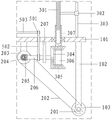
The transmission assembly 2 comprises a first transmission wheel 201, a first transmission belt 202, a second transmission wheel 203, a first bevel gear 204, a second bevel gear 205, a first rotating shaft 206 and a fixed seat 207;
a second driving wheel 203 is arranged below the bedplate 101, the wheel 103 is coaxially connected with a first driving wheel 201, and the second driving wheel 203 and the first driving wheel 201 are in driving connection through a first driving belt 202; the second driving wheel 203 is coaxially connected with a first bevel gear 204; the bottom surface of the sweep 101 is further connected with a fixed seat 207, a first rotating shaft 206 penetrates through and is rotatably connected with the fixed seat 207, a second bevel gear 205 is fixedly connected to the left end of the first rotating shaft 206, and the second bevel gear 205 is vertically meshed with the first bevel gear 204.
The lifting component 3 comprises a lifting screw 301, a sliding sleeve 302, a sliding rod 303, an incomplete bevel gear 304, a driven bevel gear 305, a second rotating shaft 306 and an internal thread cylinder 307;
an incomplete bevel gear 304 is fixedly connected to the right end of the first rotating shaft 206; the second rotating shaft 306 vertically penetrates through and is rotatably connected with the vehicle plate 101; the lower section of the second rotating shaft 306 is symmetrically and fixedly connected with a driven bevel gear 305, and the incomplete bevel gear 304 is matched with the driven bevel gear 305; an internal thread cylinder 307 is processed on the upper section of the second rotating shaft 306 and is in threaded connection with the lifting screw 301; the sweep 101 is also connected with a vertical sliding rod 303, the sliding rod 303 is sleeved with a sliding sleeve 302, and the sliding sleeve 302 is connected with a lifting screw 301.
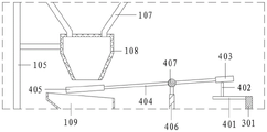
The blanking assembly 4 comprises a connecting frame 401, a push rod 402, an end plate 403, a lever 404, a baffle 405, a first support frame 406 and a torsion spring 407;
the first support frame 406 is connected to the vehicle plate 101; the middle section of the lever 404 is hinged with the top end of the first support frame 406, and a torsion spring 407 is arranged at the hinged position; torsion spring 407 makes lever 404 always have a clockwise rotation tendency; the right end of the lever 404 is connected with an end plate 403, and the left end extends to the lower part of the bottom end of the relay cylinder 108 and is connected with a baffle plate 405; the left side of the lifting screw 301 is connected with a connecting frame 401, a push rod 402 is connected to the connecting frame 401, and the push rod 402 is located below the end plate 403 and is arranged corresponding to the end plate 403.
The fertilizing assembly 5 comprises a transmission wheel set 501, a second transmission belt 502, a third rotating shaft 503, a worm 504, a worm wheel 505, a fourth rotating shaft 506, an arc-shaped blade 507, a cover body 508, a fertilizing disc 509 and a discharging nozzle 510;
a cover 508 is fixed on the bottom surface of the vehicle plate 101, the bottom end of the cover 508 is connected with a fertilizing disc 509, and the front side and the rear side of the fertilizing disc 509 are connected with a discharging nozzle 510; the bottom end of the receiving hopper 109 penetrates through the vehicle plate 101 and is communicated with the cover 508; the fourth rotating shaft 506 penetrates through and is rotatably connected with the vehicle plate 101; the bottom end of the fourth rotating shaft 506 penetrates through the cover body 508 and extends into the fertilizing disc 509, and arc-shaped blades 507 are uniformly connected in the circumferential direction; the third rotating shaft 503 penetrates through and is rotatably connected with the first supporting frame 406, the left end of the third rotating shaft is connected with a worm 504, and the right end of the third rotating shaft and the first rotating shaft 206 are correspondingly provided with a transmission wheel set 501; the transmission wheel sets 501 are in transmission connection through a second transmission belt 502; a worm wheel 505 is fixedly connected to the top end of the fourth rotating shaft 506, and the worm wheel 505 is meshed with the worm 504.
The following describes the method of using the present apparatus by taking this embodiment as an example:
moving the device into a flower cultivation greenhouse and pushing the device to move forward along the streets;
the wheel 103 rolls when advancing, and drives the coaxial first transmission wheel 201 to rotate; the first driving wheel 201 drives the second driving wheel 203 to rotate through the first driving belt 202; a first bevel gear 204 which is coaxial with the second transmission wheel 203 rotates and drives a second bevel gear 205 to drive a first rotating shaft 206 to rotate;
an incomplete bevel gear 304 at the right end of the first rotating shaft 206 also rotates immediately and is intermittently meshed with a driven bevel gear 305, so that a second rotating shaft 306 rotates forwards and backwards in a reciprocating manner; the internal thread cylinder 307 on the upper section of the second rotating shaft 306 and the lifting screw 301 immediately generate a thread effect, and the lifting screw 301 is guided by the sliding sleeve 302 and the sliding rod 303, so that the lifting screw 301 moves up and down;
the flower fertilizer in the flower fertilizer box 106 falls into the relay cylinder 108 through the blanking pipe 107; in the initial state, the baffle 405 at the left end of the lever 404 is pressed at the bottom end of the relay cylinder 108 due to the action of the torsion spring 407, and the outlet of the relay cylinder 108 is sealed; the push rod 402 is lifted along with the lifting screw 301, and gradually pushes against and pushes up the end plate 402 in the lifting process, so that the lever 404 rotates counterclockwise, and the relay cylinder 108 is opened by the baffle 405; on the contrary, in the descending process of the push rod 402, the action of the push rod 402 with the end plate 402 is gradually lost, and the lever 404 enables the baffle 405 to block the relay cylinder 108 again under the action of the torsion spring 407; thus, the intermittent blanking of the relay cylinder 108 is realized;
the flower fertilizer falling from the relay cylinder 108 is received by the receiving hopper 109 and guided into the cover body 208, and then falls into the fertilizing tray 209;
the first rotating shaft 206 also rotates the third rotating shaft 503 through the action of the transmission wheel set 501 and the second transmission belt 502; the worm 504 at the left end of the third rotating shaft 503 also rotates, and drives the worm wheel 505 to drive the fourth rotating shaft 506 to rotate, so that the arc-shaped blade 507 rotates in the fertilizing tray 509; the flower fertilizer is acted on the fertilizing disc 509 by the arc-shaped blades 507 to generate centrifugal motion and is thrown out from the discharging nozzle 510;
along with the advance of equipment, need not to set up electrical equipment such as motor, can realize applying the flower fertilizer to the flowers of both sides.
In another embodiment, the post 402 is a threaded rod vertically penetrating and threadedly engaged with the frame 401, and the bottom end of the post is provided with a hand wheel 408.
Specifically, the hand wheel 408 is used for rotating the ejector rod 402 to adjust the extension amount of the ejector rod 402 relative to the connecting frame 401, so as to adjust the amplitude and duration of the ejector rod 402 for jacking the end plate 403, change the opening amplitude and opening time of the bottom end of the relay cylinder 108, and realize the adjustment of the blanking amount of the relay cylinder 108.
Example 3
Since the flower fertilizer box 106 may contain different components of the flower fertilizer, the flower fertilizer may be applied unevenly by using the apparatus of the above embodiment.
On the basis of the example 2, the method comprises the following steps of,
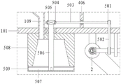
also comprises a stirring component 6; the stirring assembly 6 comprises a rack 601, a driven gear 602, a fifth rotating shaft 603, a second support frame 604, a third bevel gear 605, a fourth bevel gear 606, a stirring shaft 607 and a stirring rod 608;
a stirring shaft 607 is arranged in the relay cylinder 108, and the lower section of the stirring shaft 607 is uniformly connected with stirring rods 608; the top end of the stirring shaft 607 extends out of the relay cylinder 108 and is fixedly connected with a fourth bevel gear 606; the second support frame 604 is connected to the right side of the relay cylinder 108, and the fifth rotating shaft 603 horizontally penetrates through and is rotatably connected with the second support frame 604; the left end of the fifth rotating shaft 603 is fixedly connected with a third bevel gear 605, and the right end is fixedly connected with a driven gear 602; a third bevel gear 605 and a fourth bevel gear 606 are vertically meshed; the top end of the lifting screw 301 is connected with a rack 601, and the rack 601 is meshed with a driven gear 602.
Specifically, the rack 601 moves up and down along with the lifting screw 301, and drives the driven gear 602 to drive the fifth rotating shaft 603 to rotate; the third bevel gear 605 at the left end of the fifth rotating shaft 603 rotates along with the fifth rotating shaft, and drives the fourth bevel gear 606 to drive the stirring shaft 607 to rotate, so that the stirring rod 608 generates a stirring effect in the relay cylinder 108, and the uniformity of the flower fertilizer is improved.
In another embodiment, the stirring shaft 607 is further provided with a rotating disc 609, and the rotating disc 609 is positioned in the relay cylinder 108 and is attached to the inner top of the relay cylinder 108; the rotating disk 609 is further provided with a material through opening 610, and the material through opening 610 corresponds to the outlet at the bottom end of the blanking pipe 107.
Specifically, the stirring shaft 607 rotates with the rotating disk 609, so that the material passing opening 610 intermittently coincides with the outlet at the bottom end of the blanking pipe 107, thereby realizing intermittent feeding of the blanking pipe 107 to the relay box 108 and avoiding excessive feeding at one time.
Example 4
On the basis of the above-described embodiments,
the inner diameter of the lower part of the receiving hopper 109 is smaller than that of the upper part, and the upper part of the receiving hopper 109 is in a flaring state towards the left, so that the receiving and guiding are realized, but the lower part of the receiving hopper 109 is easy to block;
therefore, a through-feed assembly 7 is also provided; the material passing component 7 comprises a second pull rope 701, a dredging rod 702, a guide seat 703 and a protrusion 704;
the upper part of the inner wall of the right side of the receiving hopper 109 is fixedly connected with spaced guide seats 703; the dredging rod 702 vertically penetrates through the guide seat 703 and extends downwards into the lower part of the receiving hopper 109; the top end of the dredging rod 702 is connected with the lever 404 through a second pull rope 701; the lower section of the dredging rod 702 is also provided with a plurality of bulges 704.
Specifically, when the blanking assembly 4 works, the lever 404 acts on the dredging rod 702 through the second pull rope 701, the self weight of the dredging rod 702 is matched, the dredging rod 702 moves up and down, and the matching protrusion 704 is used for dredging the lower part of the hopper 109 to avoid blockage.
In the description herein, references to the description of "one embodiment," "an example," "a specific example," etc., mean that a particular feature, structure, or characteristic described in connection with the embodiment or example is included in at least one embodiment or example of the present invention. In this specification, the schematic representations of the terms used above do not necessarily refer to the same embodiment or example. Furthermore, the particular features, structures, materials, or characteristics described may be combined in any suitable manner in any one or more embodiments or examples.
The preferred embodiments of the invention disclosed above are intended to be illustrative only. The preferred embodiments are not intended to be exhaustive or to limit the invention to the precise form disclosed. Obviously, many modifications and variations are possible in light of the above teaching. The embodiments were chosen and described in order to best explain the principles of the invention and the practical application, to thereby enable others skilled in the art to best understand the invention for and utilize the invention. The invention is limited only by the claims and their full scope and equivalents.
Claims (6)
1. Auxiliary equipment for flower cultivation is characterized by comprising a vehicle body assembly (1), a transmission assembly (2), a lifting assembly (3), a blanking assembly (4) and a fertilizing assembly (5);
the vehicle body assembly (1) comprises a vehicle plate (101), a wheel carrier (102), wheels (103), a push handle (104), a fixing frame (105), a flower fertilizer box (106), a discharging pipe (107), a relay cylinder (108) and a receiving hopper (109); the left side of the vehicle plate (101) is connected with a push handle (104), and the bottom of the vehicle plate (101) is connected with a wheel (103) through a wheel carrier (102); the left end of the turning plate (101) is connected with a fixing frame (105), the top of the fixing frame (105) is connected with a plurality of flower fertilizer boxes (106), and the bottoms of the flower fertilizer boxes (106) are communicated with the top of the relay cylinder (108) through a discharging pipe (107);
the lifting component (3) is arranged on the right part of the sweep (101), and the lifting component (3) is connected with wheels (103) through a transmission component (2); the blanking assembly (4) is arranged at the bottom of the relay cylinder (108), and the blanking assembly (4) is matched with the lifting assembly (3); the vehicle plate (101) is also provided with a fertilization component (5), and the fertilization component (5) is also matched with the transmission component (2); the receiving hopper (109) is positioned below the relay cylinder (108), and the bottom end of the receiving hopper penetrates through the vehicle plate (101) and extends into the fertilizing assembly (5);
the transmission assembly (2) comprises a first transmission wheel (201), a first transmission belt (202), a second transmission wheel (203), a first bevel gear (204), a second bevel gear (205), a first rotating shaft (206) and a fixed seat (207);
a second driving wheel (203) is arranged below the turning plate (101), the wheel (103) is coaxially connected with a first driving wheel (201), and the second driving wheel (203) is in transmission connection with the first driving wheel (201) through a first transmission belt (202); the second driving wheel (203) is coaxially connected with a first bevel gear (204); the bottom surface of the sweep (101) is further connected with a fixed seat (207), a first rotating shaft (206) penetrates through and is rotatably connected with the fixed seat (207), a second bevel gear (205) is arranged at the left end of the first rotating shaft (206), and the second bevel gear (205) is vertically meshed with the first bevel gear (204);
the lifting assembly (3) comprises a lifting screw (301), a sliding sleeve (302), a sliding rod (303), an incomplete bevel gear (304), a driven bevel gear (305), a second rotating shaft (306) and an internal thread cylinder (307);
an incomplete bevel gear (304) is arranged at the right end of the first rotating shaft (206); the second rotating shaft (306) vertically penetrates through and is rotatably connected with the vehicle plate (101); a driven bevel gear (305) is symmetrically arranged at the lower section of the second rotating shaft (306), and the incomplete bevel gear (304) is matched with the driven bevel gear (305); the upper section of the second rotating shaft (306) is provided with an internal thread cylinder (307) which is in threaded connection with a lifting screw (301); the sweeping board (101) is also connected with a vertical sliding rod (303), a sliding sleeve (302) is arranged on the sliding rod (303), and the sliding sleeve (302) is connected with the lifting screw (301);
the blanking assembly (4) comprises a connecting frame (401), a push rod (402), an end plate (403), a lever (404), a baffle (405), a first support frame (406) and a torsion spring (407);
a first support frame (406) is connected to the vehicle plate (101); the middle section of the lever (404) is hinged with the top end of the first support frame (406), and a torsion spring (407) is arranged at the hinged position; the torsion spring (407) enables the lever (404) to always have a clockwise rotation tendency; the right end of the lever (404) is provided with an end plate (403), and the left end of the lever extends to the lower part of the bottom end of the relay cylinder (108) and is connected with a baffle plate (405); the left side of the lifting screw (301) is connected with a connecting frame (401), a push rod (402) is arranged on the connecting frame (401), and the push rod (402) is positioned below the end plate (403) and arranged corresponding to the end plate (403);
the fertilizing assembly (5) comprises a transmission wheel set (501), a second transmission belt (502), a third rotating shaft (503), a worm (504), a worm wheel (505), a fourth rotating shaft (506), arc-shaped blades (507), a cover body (508), a fertilizing disc (509) and a discharging nozzle (510);
a cover body (508) is arranged on the bottom surface of the vehicle plate (101), the bottom end of the cover body (508) is connected with a fertilization disk (509), and the front side and the rear side of the fertilization disk (509) are connected with discharge nozzles (510); the bottom end of the receiving hopper (109) penetrates through the vehicle plate (101) and is communicated with the cover body (508); the fourth rotating shaft (506) penetrates through and is rotatably connected with the vehicle plate (101); the bottom end of the fourth rotating shaft (506) penetrates through the cover body (508) and extends into the fertilizing disc (509) and is uniformly connected with arc-shaped blades (507) in the circumferential direction; the third rotating shaft (503) penetrates through and is rotatably connected with the first supporting frame (406), the left end of the third rotating shaft is connected with the worm (504), and the right end of the third rotating shaft and the first rotating shaft (206) are correspondingly provided with the transmission wheel set (501); the transmission wheel sets (501) are in transmission connection through a second transmission belt (502); the top end of the fourth rotating shaft (506) is provided with a worm wheel (505), and the worm wheel (505) is meshed with the worm (504).
2. An auxiliary device for cultivating flowers as claimed in claim 1, wherein the top bar (402) is a threaded rod vertically penetrating and screwed into the connecting frame (401), and a hand wheel (408) is arranged at the bottom end.
3. An auxiliary device for flower cultivation according to claim 1 or 2, further comprising a stirring member (6); the stirring assembly (6) comprises a rack (601), a driven gear (602), a fifth rotating shaft (603), a second supporting frame (604), a third bevel gear (605), a fourth bevel gear (606), a stirring shaft (607) and a stirring rod (608);
a stirring shaft (607) is arranged in the relay cylinder (108), and stirring rods (608) are uniformly arranged at the lower section of the stirring shaft (607); the top end of the stirring shaft (607) extends out of the relay cylinder (108) upwards and is provided with a fourth bevel gear (606); a second support frame (604) is arranged on the right side of the relay cylinder (108), and a fifth rotating shaft (603) horizontally penetrates through and is rotatably connected with the second support frame (604); a third bevel gear (605) is arranged at the left end of the fifth rotating shaft (603), and a driven gear (602) is arranged at the right end of the fifth rotating shaft; the third bevel gear (605) and the fourth bevel gear (606) are vertically meshed; the top end of the lifting screw (301) is connected with a rack (601), and the rack (601) is meshed with the driven gear (602).
4. A flower cultivating auxiliary device as claimed in claim 3, wherein said stirring shaft (607) is further provided with a rotating disc (609), said rotating disc (609) is located in the relay cylinder (108) and clings to the inner top of the relay cylinder (108); the turntable (609) is also provided with a material through hole (610), and the material through hole (610) corresponds to the outlet at the bottom end of the blanking pipe (107); when the rotating disc (609) rotates, the material passing opening (610) is intermittently superposed with the outlet at the bottom end of the blanking pipe (107).
5. An auxiliary device for flower cultivation, as claimed in claim 1, wherein the inner diameter of the lower part of the receiving hopper (109) is smaller than the inner diameter of the upper part thereof, and the upper part of the receiving hopper (109) is formed in a state of being flared to the left.
6. A flower cultivation aid according to claim 5, further comprising a aeration assembly (7); the material passing assembly (7) comprises a second pull rope (701), a dredging rod (702), a guide seat (703) and a protrusion (704);
the upper part of the inner wall of the right side of the receiving hopper (109) is provided with guide seats (703) at intervals; the dredging rod (702) vertically penetrates through the guide seat (703) and extends downwards into the lower part of the receiving hopper (109); the top end of the dredging rod (702) is connected with the lever (404) through a second pull rope (701); the lower section of the dredging rod (702) is also provided with a plurality of bulges (704).
Priority Applications (1)
| Application Number | Priority Date | Filing Date | Title |
|---|---|---|---|
| CN202011627930.1A CN112840820B (en) | 2020-12-31 | 2020-12-31 | Auxiliary assembly for flower cultivation |
Applications Claiming Priority (1)
| Application Number | Priority Date | Filing Date | Title |
|---|---|---|---|
| CN202011627930.1A CN112840820B (en) | 2020-12-31 | 2020-12-31 | Auxiliary assembly for flower cultivation |
Publications (2)
| Publication Number | Publication Date |
|---|---|
| CN112840820A CN112840820A (en) | 2021-05-28 |
| CN112840820B true CN112840820B (en) | 2022-10-11 |
Family
ID=75999686
Family Applications (1)
| Application Number | Title | Priority Date | Filing Date |
|---|---|---|---|
| CN202011627930.1A Active CN112840820B (en) | 2020-12-31 | 2020-12-31 | Auxiliary assembly for flower cultivation |
Country Status (1)
| Country | Link |
|---|---|
| CN (1) | CN112840820B (en) |
Families Citing this family (2)
| Publication number | Priority date | Publication date | Assignee | Title |
|---|---|---|---|---|
| CN115280938B (en) * | 2022-07-06 | 2024-04-09 | 黑龙江省农业科学院乡村振兴科技研究所 | Fertilizer applying device of wheat breeding dibbler and operation method |
| CN115212803B (en) * | 2022-07-31 | 2024-04-05 | 溧阳市金昆锻压有限公司 | Biomass fuel granulator die |
Citations (12)
| Publication number | Priority date | Publication date | Assignee | Title |
|---|---|---|---|---|
| FR2620588A1 (en) * | 1987-09-23 | 1989-03-24 | Moyat Yves | Universal spreading barrow |
| CN106358544A (en) * | 2016-10-31 | 2017-02-01 | 鲍兆伟 | Agricultural centrifugal fertilizer-spreading device |
| CN206165170U (en) * | 2016-09-29 | 2017-05-17 | 漳浦绿野生态农业科技有限公司 | Vegetables fertilizer injection unit |
| CN107896578A (en) * | 2017-11-16 | 2018-04-13 | 安徽永生堂药业有限责任公司 | A kind of agricultural uses corn planting device |
| CN108167014A (en) * | 2017-11-27 | 2018-06-15 | 湖南望隆企业管理咨询有限公司 | A kind of mine site packaged type device for reducing dust |
| CN108271494A (en) * | 2018-03-13 | 2018-07-13 | 傅志坚 | A kind of animal husbandry herbage fertilizer apparatus |
| CN108401630A (en) * | 2018-03-31 | 2018-08-17 | 石家庄皇川农业科技有限公司 | A kind of agricultural fertilizer sowing apparatus |
| CN108811643A (en) * | 2018-06-02 | 2018-11-16 | 贾英新 | Granular chemical fertilizer manual machine is put in a kind of shallot plantation top dressing ditch |
| CN109000991A (en) * | 2018-10-24 | 2018-12-14 | 吉林建筑大学 | A kind of underground Organic substance in water sampler |
| CN111010939A (en) * | 2019-12-26 | 2020-04-17 | 长兴青茂农业发展有限公司 | Agricultural planting equipment integrating digging, sowing and fertilizing |
| CN111346558A (en) * | 2020-03-25 | 2020-06-30 | 新沂市东方硕华光学材料有限公司 | Low refracting index optical coating material production raw materials mixing arrangement |
| CN111771495A (en) * | 2020-06-29 | 2020-10-16 | 安徽理工大学 | Walking type automatic fertilizing robot |
-
2020
- 2020-12-31 CN CN202011627930.1A patent/CN112840820B/en active Active
Patent Citations (12)
| Publication number | Priority date | Publication date | Assignee | Title |
|---|---|---|---|---|
| FR2620588A1 (en) * | 1987-09-23 | 1989-03-24 | Moyat Yves | Universal spreading barrow |
| CN206165170U (en) * | 2016-09-29 | 2017-05-17 | 漳浦绿野生态农业科技有限公司 | Vegetables fertilizer injection unit |
| CN106358544A (en) * | 2016-10-31 | 2017-02-01 | 鲍兆伟 | Agricultural centrifugal fertilizer-spreading device |
| CN107896578A (en) * | 2017-11-16 | 2018-04-13 | 安徽永生堂药业有限责任公司 | A kind of agricultural uses corn planting device |
| CN108167014A (en) * | 2017-11-27 | 2018-06-15 | 湖南望隆企业管理咨询有限公司 | A kind of mine site packaged type device for reducing dust |
| CN108271494A (en) * | 2018-03-13 | 2018-07-13 | 傅志坚 | A kind of animal husbandry herbage fertilizer apparatus |
| CN108401630A (en) * | 2018-03-31 | 2018-08-17 | 石家庄皇川农业科技有限公司 | A kind of agricultural fertilizer sowing apparatus |
| CN108811643A (en) * | 2018-06-02 | 2018-11-16 | 贾英新 | Granular chemical fertilizer manual machine is put in a kind of shallot plantation top dressing ditch |
| CN109000991A (en) * | 2018-10-24 | 2018-12-14 | 吉林建筑大学 | A kind of underground Organic substance in water sampler |
| CN111010939A (en) * | 2019-12-26 | 2020-04-17 | 长兴青茂农业发展有限公司 | Agricultural planting equipment integrating digging, sowing and fertilizing |
| CN111346558A (en) * | 2020-03-25 | 2020-06-30 | 新沂市东方硕华光学材料有限公司 | Low refracting index optical coating material production raw materials mixing arrangement |
| CN111771495A (en) * | 2020-06-29 | 2020-10-16 | 安徽理工大学 | Walking type automatic fertilizing robot |
Also Published As
| Publication number | Publication date |
|---|---|
| CN112840820A (en) | 2021-05-28 |
Similar Documents
| Publication | Publication Date | Title |
|---|---|---|
| CN112840820B (en) | Auxiliary assembly for flower cultivation | |
| CN101150951A (en) | Method and apparatus for growing plants | |
| CN113079727B (en) | Integrated device is cultivateed to afforestation seedling cultivation | |
| CN208754649U (en) | A kind of small-sized weeder of agricultural planting | |
| CN209218760U (en) | A kind of organic vegetable greenhouse gardening device | |
| CN210928530U (en) | Agricultural robot | |
| CN213094889U (en) | Grass planting device for landscaping | |
| CN109983877A (en) | A kind of disinfection seeding apparatus for seed | |
| CN213907495U (en) | Nursery fertilizer injection unit that grows seedlings | |
| CN114557158A (en) | Environment-friendly auxiliary mechanism for improving survival rate of bird's nest fruit | |
| CN210630362U (en) | Tea-oil camellia tree is planted and fertilizes pre-buried device | |
| CN113678591A (en) | Forestry is planted with soil reclamation fertilization integration mechanism | |
| CN113853854A (en) | Utilize grape of biomass energy to plant with dark pine fertilizer distributor | |
| CN208300238U (en) | A kind of flower seed planter | |
| CN112868300A (en) | Garden art is with flower kind seeder | |
| CN112753340A (en) | Newly-transplanted seedling root maintenance auxiliary device | |
| CN207733242U (en) | Water integrated device is applied in a kind of orchard | |
| CN218042991U (en) | A water jet equipment for seedling planting | |
| CN217547080U (en) | Green curing means that plants in gardens | |
| CN220457891U (en) | Fertilizing and seeding machine | |
| CN217608349U (en) | Fertilizer injection unit of usefulness is planted to cherry | |
| CN209731953U (en) | Jaboticaba cultivation equipment | |
| CN212279612U (en) | Saline and alkaline land tomato is planted with spouting medicine device | |
| CN212728027U (en) | Fertilizer injection unit is planted to crassula argentea | |
| CN113785813B (en) | Equipment convenient for spraying liquid medicine on grapes |
Legal Events
| Date | Code | Title | Description |
|---|---|---|---|
| PB01 | Publication | ||
| PB01 | Publication | ||
| SE01 | Entry into force of request for substantive examination | ||
| SE01 | Entry into force of request for substantive examination | ||
| TA01 | Transfer of patent application right |
Effective date of registration: 20220915 Address after: 362000 No. 62, Xizhou new village, Shuangxi village, Fengzhou Town, Nan'an City, Quanzhou City, Fujian Province Applicant after: Wang Xiaoling Address before: 230000 202, building 13, Swan Garden, Hezuo Hua Road, Shushan District, Hefei City, Anhui Province Applicant before: Anhui saichi Communication Technology Co.,Ltd. |
|
| TA01 | Transfer of patent application right | ||
| GR01 | Patent grant | ||
| GR01 | Patent grant |