CN112839296B - Apparatus and method for implementing SAOC down-mixing of 3D audio content - Google Patents
Apparatus and method for implementing SAOC down-mixing of 3D audio content Download PDFInfo
- Publication number
- CN112839296B CN112839296B CN202011323152.7A CN202011323152A CN112839296B CN 112839296 B CN112839296 B CN 112839296B CN 202011323152 A CN202011323152 A CN 202011323152A CN 112839296 B CN112839296 B CN 112839296B
- Authority
- CN
- China
- Prior art keywords
- audio
- information
- channels
- mix
- audio transmission
- Prior art date
- Legal status (The legal status is an assumption and is not a legal conclusion. Google has not performed a legal analysis and makes no representation as to the accuracy of the status listed.)
- Active
Links
Images


Classifications
-
- H—ELECTRICITY
- H04—ELECTRIC COMMUNICATION TECHNIQUE
- H04S—STEREOPHONIC SYSTEMS
- H04S3/00—Systems employing more than two channels, e.g. quadraphonic
- H04S3/02—Systems employing more than two channels, e.g. quadraphonic of the matrix type, i.e. in which input signals are combined algebraically, e.g. after having been phase shifted with respect to each other
-
- G—PHYSICS
- G10—MUSICAL INSTRUMENTS; ACOUSTICS
- G10L—SPEECH ANALYSIS OR SYNTHESIS; SPEECH RECOGNITION; SPEECH OR VOICE PROCESSING; SPEECH OR AUDIO CODING OR DECODING
- G10L19/00—Speech or audio signals analysis-synthesis techniques for redundancy reduction, e.g. in vocoders; Coding or decoding of speech or audio signals, using source filter models or psychoacoustic analysis
- G10L19/008—Multichannel audio signal coding or decoding using interchannel correlation to reduce redundancy, e.g. joint-stereo, intensity-coding or matrixing
-
- H—ELECTRICITY
- H04—ELECTRIC COMMUNICATION TECHNIQUE
- H04S—STEREOPHONIC SYSTEMS
- H04S3/00—Systems employing more than two channels, e.g. quadraphonic
-
- H—ELECTRICITY
- H04—ELECTRIC COMMUNICATION TECHNIQUE
- H04S—STEREOPHONIC SYSTEMS
- H04S3/00—Systems employing more than two channels, e.g. quadraphonic
- H04S3/006—Systems employing more than two channels, e.g. quadraphonic in which a plurality of audio signals are transformed in a combination of audio signals and modulated signals, e.g. CD-4 systems
-
- H—ELECTRICITY
- H04—ELECTRIC COMMUNICATION TECHNIQUE
- H04S—STEREOPHONIC SYSTEMS
- H04S3/00—Systems employing more than two channels, e.g. quadraphonic
- H04S3/008—Systems employing more than two channels, e.g. quadraphonic in which the audio signals are in digital form, i.e. employing more than two discrete digital channels
-
- H—ELECTRICITY
- H04—ELECTRIC COMMUNICATION TECHNIQUE
- H04S—STEREOPHONIC SYSTEMS
- H04S7/00—Indicating arrangements; Control arrangements, e.g. balance control
- H04S7/30—Control circuits for electronic adaptation of the sound field
- H04S7/305—Electronic adaptation of stereophonic audio signals to reverberation of the listening space
-
- H—ELECTRICITY
- H04—ELECTRIC COMMUNICATION TECHNIQUE
- H04S—STEREOPHONIC SYSTEMS
- H04S2400/00—Details of stereophonic systems covered by H04S but not provided for in its groups
- H04S2400/01—Multi-channel, i.e. more than two input channels, sound reproduction with two speakers wherein the multi-channel information is substantially preserved
-
- H—ELECTRICITY
- H04—ELECTRIC COMMUNICATION TECHNIQUE
- H04S—STEREOPHONIC SYSTEMS
- H04S2400/00—Details of stereophonic systems covered by H04S but not provided for in its groups
- H04S2400/03—Aspects of down-mixing multi-channel audio to configurations with lower numbers of playback channels, e.g. 7.1 -> 5.1
-
- H—ELECTRICITY
- H04—ELECTRIC COMMUNICATION TECHNIQUE
- H04S—STEREOPHONIC SYSTEMS
- H04S2400/00—Details of stereophonic systems covered by H04S but not provided for in its groups
- H04S2400/11—Positioning of individual sound objects, e.g. moving airplane, within a sound field
-
- H—ELECTRICITY
- H04—ELECTRIC COMMUNICATION TECHNIQUE
- H04S—STEREOPHONIC SYSTEMS
- H04S2400/00—Details of stereophonic systems covered by H04S but not provided for in its groups
- H04S2400/13—Aspects of volume control, not necessarily automatic, in stereophonic sound systems
-
- H—ELECTRICITY
- H04—ELECTRIC COMMUNICATION TECHNIQUE
- H04S—STEREOPHONIC SYSTEMS
- H04S2420/00—Techniques used stereophonic systems covered by H04S but not provided for in its groups
- H04S2420/03—Application of parametric coding in stereophonic audio systems
Abstract
An apparatus and method for implementing SAOC down-mixing of 3D audio content are provided. The device comprises: a parameter processor (110) for calculating output channel mix information, and a downmix processor (120) for generating the one or more audio output channels. The downmix processor (120) is configured to receive an audio transport signal comprising one or more audio transport channels, wherein two or more audio object signals are mixed in the audio transport signal, and wherein a number of the one or more audio transport channels is smaller than a number of the two or more audio object signals. The audio transmission signal depends on a first mixing rule and a second mixing rule. The first mixing rule indicates how to mix the two or more audio object signals to obtain a plurality of pre-mixed channels.
Description
The present application is a divisional application of chinese patent application with application number "201480041327.1", application number "apparatus and method for realizing SAOC downmixing of 3D audio content", having application number of 2014, 7, 16.
Technical Field
The present invention relates to audio encoding/decoding, and more particularly, to spatial audio encoding and spatial audio object encoding, and more particularly, to an apparatus and method for implementing SAOC down-mixing of three-dimensional audio content, and an apparatus and method for efficiently decoding the SAOC down-mixing of three-dimensional audio content.
Prior Art
Spatial audio coding tools are well known in the art, for example, standardized specifications exist in the surround MPEG standard. Spatial audio coding starts from an original input channel, e.g. five or seven channels, i.e. a left channel, a center channel, a right channel, a left surround channel, a right surround channel and a low frequency enhancement channel, identified in the reproduction equipment according to their position. Spatial audio encoders typically derive at least one downmix channel from an original channel and, in addition, parametric data about spatial cues, such as inter-channel level differences, inter-channel phase differences, inter-channel time differences, etc. At least one downmix channel is transferred to a spatial audio decoder together with parametric side information (parametric side information, otherwise referred to as parametric side information, parameter side information or parameter side information) indicative of the spatial cues, the spatial audio decoder decodes the downmix channel and associated parametric data, and finally obtains an output channel being an approximated version of the original input channel. The placement of the channels at the output equipment is typically fixed, e.g., 5.1 channel format or 7.1 channel format, etc.
Such channel-based audio formats are widely used for storing or transmitting multi-channel audio content, with each channel being associated with a particular speaker at a given location. Faithful reproduction of these kinds of formats requires speaker equipment in which speakers are placed in the same positions as speakers used during audio signal production. While increasing the number of loudspeakers may improve the reproduction of a real three-dimensional virtual reality scene, it is increasingly difficult to meet this requirement, especially in a home environment, like a living room.
The need for a special speaker device can be overcome with an object-based approach in which speaker signals are rendered specifically for playback equipment.
For example, spatial audio object coding tools are well known in the art and are already standardized in the MPEG SAOC (saoc= spatial audio object coding spatial audio object coding) standard. Compared to spatial audio coding starting from the original channel, spatial audio object coding starts from audio objects that are not automatically dedicated to the particular rendering equipment. Instead, the position of the audio object in the reproduction scene may vary and may be determined by the user by inputting specific rendering information to the spatial audio object codec. Alternatively or additionally, rendering information, i.e. position information in the rendering equipment where a specific audio object is to be placed, is transferred with additional auxiliary information or metadata. In order to obtain a specific data compression, the plurality of audio objects are encoded by an SAOC encoder, which down-mixes the objects according to specific down-mix information to calculate at least one transmission channel from the input objects. In addition, the SAOC encoder calculates parameterized side information representing inter-object cues, such as Object Level Differences (OLDs), object coherence values, and the like. Inter-object parameter data is calculated for parameter time tiling/frequency tiling, i.e. for a specific frame of the audio signal (e.g. 1024 or 2048 samples), a plurality of processing bands (e.g. 28, 20, 14 or 10 processing bands, etc.) are considered such that there is parameter data for each frame as well as for each processing band. By way of example, when an audio tile has 20 frames and when each frame is subdivided into 28 processing bands, then the number of time/frequency tiles is 560.
In the object-based approach, the sound field is described in terms of separate audio objects. This requires object metadata describing the time-varying position of each sound source in 3D space.
In the prior art, the first metadata encoding concept is spatial sound description interchange format (spacdif), and the audio scene description format is currently under development [ M1]. The audio scene description format is an object-based sound scene exchange format that does not provide any way to compress object trajectories. The SpatDIF uses a text-based Open Sound Control (OSC) format for the structure of object metadata [ M2]. However, simple text-based representations are not an option for compressed transmission of object trajectories.
In the prior art, another metadata concept is the Audio Scene Description Format (ASDF) [ M3], which is a text-based solution with the same drawbacks. This data is structured by an extension of the Synchronized Multimedia Integration Language (SMIL), which is a subset of the extensible markup language (XML) [ M4], [ M5 ].
Another metadata concept in the prior art is audio binary format (AudioBIFS) of a scene, binary format [ M6], [ M7] that is part of the MPEG-4 standard. It is highly relevant to the XML-based Virtual Reality Modeling Language (VRML), which has been developed for application to audio virtual 3D scenes as well as interactive virtual reality [ M8]. The complex AudioBIFS standard uses a scene graph to specify the path of the object movement. The main disadvantage of AudioBIFS is that it is not designed for real-time operation, where a limited system delay is incurred and a random read of the data stream is required. Furthermore, the encoding of object positions does not exploit the limited positioning capabilities of listeners. When a listener in an audio virtual scene has a fixed location, then the object data may be quantized to a lower number of bits [ M9]. Therefore, the encoding of object metadata applied to AudioBIFS is ineffective for data compression.
Disclosure of Invention
It is an object of the invention to provide an improved concept for downmixing audio content. The object of the invention is solved by an apparatus according to claim 1, an apparatus according to claim 9, a system according to claim 12, a method according to claim 13, a method according to claim 14 and a computer program according to claim 15.
According to embodiments, efficient transmission is achieved and a way of decoding down-mix of three-dimensional audio content is provided.
An apparatus for generating one or more audio output channels is provided. The device includes a parameter processor for calculating output channel mix information and a downmix processor for generating the one or more audio output channels. The downmix processor is configured to receive an audio transmission signal comprising one or more audio transmission channels, wherein two or more audio object signals are mixed in the audio transmission signal, and wherein a number of the one or more audio transmission channels is smaller than a number of the two or more audio object signals. The audio transmission signal depends on a first mixing rule and a second mixing rule. The first mixing rule indicates how to mix the two or more audio object signals to obtain a plurality of pre-mixed channels. Furthermore, the second mixing rule indicates how to mix the plurality of pre-mixed channels to obtain one or more audio transmission channels of the audio transmission signal. The parameter processor is configured to receive information of the second mixing rule, wherein the information of the second mixing rule indicates how to mix the plurality of pre-mixed signals such that the one or more audio transmission channels are obtained. Further, the parameter processor is configured to calculate the output channel mix information based on a number of audio objects indicating the number of the two or more audio object signals, a number of premixed channels indicating the number of the plurality of premixed channels, and information of the second mixing rule. The downmix processor is configured to generate one or more audio output channels from the audio transmission signal based on the output channel mixing information.
Furthermore, the invention provides an apparatus for generating an audio transmission signal comprising one or more audio transmission channels. The apparatus comprises an object mixer for generating the audio transmission signal comprising one or more audio transmission channels from the two or more audio object signals such that the two or more audio object signals are mixed in the audio transmission signal, and wherein the number of the one or more audio transmission channels is smaller than the number of the two or more audio object signals, and an output interface for outputting the audio transmission signal. The object mixer is configured to generate one or more audio transmission channels of the audio transmission signal according to a first mixing rule and a second mixing rule, wherein the first mixing rule indicates how to mix the two or more audio object signals to obtain a plurality of pre-mixed channels, and wherein the second mixing rule indicates how to mix the plurality of pre-mixed channels to obtain the one or more audio transmission channels of the audio transmission signal. The first mixing rule depends on a number of audio objects indicating a number of the two or more audio object signals and a number of pre-mix channels indicating a number of the plurality of pre-mix channels, and wherein the second mixing rule depends on the number of pre-mix channels. The output interface is used for outputting the information of the second mixing rule.
Furthermore, a system is provided. The system comprises means for generating an audio transmission signal as described above, and means for generating one or more audio output channels as described above. The means for generating one or more audio output channels is for receiving the audio transmission signal and information of the second mixing rule from the means for generating an audio transmission signal. Furthermore, the means for generating one or more audio output channels is for generating the one or more audio output channels from the audio transmission signal in accordance with the information of the second mixing rule.
Furthermore, a method for generating one or more audio output channels is provided. The method comprises the following steps:
-receiving an audio transmission signal comprising one or more audio transmission channels, wherein two or more audio object signals are mixed in the audio transmission signal, and wherein the number of the one or more audio transmission channels is smaller than the number of the two or more audio object signals, wherein the audio transmission signal depends on a first mixing rule and a second mixing rule, wherein the first mixing rule indicates how to mix the two or more audio object signals to obtain a plurality of pre-mixed channels, and wherein the second mixing rule indicates how to mix a plurality of pre-mixed channels to obtain one or more audio transmission channels of the audio transmission signal.
-receiving information of the second mixing rule, wherein the information of the second mixing rule indicates how to mix the plurality of pre-mixed signals such that the one or more audio transmission channels are obtained;
-calculating output channel mixing information from the number of audio objects, the number of pre-mixed channels, and the information of the second mixing rule, the number of audio objects indicating the number of the two or more audio object signals, the number of pre-mixed channels indicating the number of the plurality of pre-mixed channels, and:
-generating one or more audio output channels from the audio transmission signal based on the output channel mix information.
Furthermore, the invention provides a method for generating an audio transmission signal comprising one or more audio transmission channels. The method comprises the following steps:
generating the audio transmission signal from two or more audio object signals, which audio transmission signal comprises one or more audio transmission channels,
-outputting the audio transmission signal, and:
-outputting information of the second mixing rule.
Generating the audio transmission signal from two or more audio object signals is performed such that two or more audio object signals are mixed in the audio transmission signal, which audio transmission signal contains the one or more audio transmission channels, wherein the number of the one or more audio transmission channels is smaller than the number of the two or more audio object signals. Generating one or more audio transmission channels of the audio transmission signal is performed according to a first mixing rule and a second mixing rule, wherein the first mixing rule indicates how to mix the two or more audio object signals to obtain a plurality of pre-mixed channels, and wherein the second mixing rule indicates how to mix the plurality of pre-mixed channels to obtain the one or more audio transmission channels of the audio transmission signal. The first mixing rule depends on a number of audio objects indicating a number of the two or more audio object signals and a number of pre-mix channels indicating a number of the plurality of pre-mix channels. The second mixing rule depends on the number of pre-mixed channels.
Furthermore, the present invention provides a computer program for implementing the method as described above when being executed on a computer or on a signal processor.
Drawings
Embodiments of the present invention are described below with reference to the accompanying drawings, in which:
fig. 1 shows an apparatus for generating one or more audio output channels according to an embodiment.
Fig. 2 shows an apparatus for generating an audio transmission signal comprising one or more audio transmission channels according to an embodiment.
Fig. 3 shows a system according to an embodiment.
Fig. 4 shows a first embodiment of a three-dimensional audio encoder.
Fig. 5 shows a first embodiment of a three-dimensional audio decoder.
Fig. 6 shows a second embodiment of a three-dimensional audio encoder.
Fig. 7 shows a second embodiment of a three-dimensional audio decoder.
Fig. 8 shows a third embodiment of a three-dimensional audio encoder.
Fig. 9 shows a third embodiment of a three-dimensional audio decoder.
Fig. 10 shows the position of an audio object represented by azimuth, elevation and radius in three-dimensional space starting from the origin.
Fig. 11 shows the positions of audio objects and speaker equipment employed by an audio channel generator.
Detailed Description
Before describing in detail the preferred embodiments of the present invention, a novel three-dimensional audio codec system is described.
In the prior art, there is no variable technique combining channel coding on the one hand and object coding on the other hand, so that acceptable audio quality is obtained at low bit rates.
This limitation can be overcome by this new three-dimensional audio codec system.
Before describing in detail the preferred embodiments of the present invention, this new three-dimensional audio codec system will be described.
Fig. 4 illustrates a 3D audio encoder according to an embodiment of the present invention. The 3D audio encoder is for encoding the audio input data 101 to obtain audio input data 501. The 3D audio encoder includes an input interface for receiving a plurality of audio channels indicated by CH and a plurality of audio objects indicated by OBJ. In addition, the input interface 1100 illustrated in fig. 4 additionally receives metadata related to at least one of the plurality of audio objects OBJ. In addition, the 3D audio encoder comprises a mixer 200 for mixing a plurality of objects and a plurality of channels to obtain a plurality of premixed channels, wherein each premixed channel comprises audio data of a channel and audio data of at least one object.
In addition, the 3D audio encoder includes a core encoder 300 for core encoding core encoder input data and a metadata compressor 400 for compressing metadata related to at least one of the plurality of audio objects.
Furthermore, the 3D audio encoder may comprise a mode controller 600 controlling the mixer, the core encoder and/or the output interface 500 in one of a plurality of operation modes, wherein the core encoder is in a first mode for encoding a plurality of audio channels and a plurality of audio objects received through the input interface 1100 without being affected by the mixer (i.e. without being mixed by the mixer 200). However, in the second mode the mixer 200 is active and the core encoder encodes a plurality of mixed channels, i.e. the output produced by the block 200. In the latter case, preferably no object data is encoded anymore. Instead, metadata indicating the location of the audio object has been used by the mixer 200 to render the object on the channel indicated by the metadata. In other words, the mixer 200 uses metadata related to the plurality of audio objects to pre-render the audio objects, which are then mixed with the channels to obtain the mixed channels at the mixer output. In this embodiment, no object may have to be transmitted, which also applies to the compressed metadata output by block 400. However, if not all of the objects of the input interface 1100 are mixed and only a specific number of the objects are mixed, only the remaining non-mixed objects and associated metadata are still transferred to the core encoder 300 or metadata compressor 400, respectively.
Fig. 6 shows another embodiment of a 3D audio encoder, the 3D audio encoder additionally comprising an SAOC encoder 800. The SAOC encoder 800 is for generating at least one transmission channel and parametric data from spatial audio object encoder input data. As shown in fig. 6, the input data of the spatial audio object encoder is an object that has not been processed via the pre-renderer/mixer. In addition, when the independent channel/object coding is active in the first mode, then the pre-renderer/mixer is bypassed and all objects input to the input interface 1100 are coded by the SAOC encoder 800.
Furthermore, as shown in fig. 6, the core encoder 300 is preferably implemented as a USAC encoder, i.e. as an encoder defined and specified in the MPEG-USAC standard (usac=joint speech and audio coding). For independent data types, all outputs of the 3D audio encoder depicted in fig. 6 are MPEG 4 data streams, MPEG H data streams, or 3D audio data streams, having a container-like structure. In addition, metadata is indicated as "OAM" data, and the metadata compressor 400 in fig. 4 corresponds to the OAM encoder 400 to obtain compressed OAM data input into the USAC encoder 300, and as shown in fig. 6, the USAC encoder 300 additionally includes an output interface for obtaining an MP4 output data stream having encoded channel/object data and compressed OAM data.
Fig. 8 shows another embodiment of a 3D audio encoder, which may be used to encode channels provided at the pre-renderer/mixer 200 that are not active in this mode using an SAOC encoding algorithm, or an SAOC encoder for SAOC encoding pre-rendered channels and objects, with respect to fig. 6. Thus, the SAOC encoder 800 in fig. 8 may operate on three different types of input data, i.e., channels without any pre-rendering objects, channels and pre-rendering objects, or independent objects. Furthermore, it is preferable to provide another OAM decoder 420 in fig. 8 so that the SAOC encoder 800 is used to process the same data as on the decoder side, i.e. lossy compression of the obtained data, instead of the original OAM data.
In fig. 8, the 3D audio encoder may operate in a plurality of independent modes.
In addition to the first mode and the second mode described in the context of fig. 4, the 3D audio encoder in fig. 8 may additionally operate in a third mode in which the core encoder generates at least one transmission channel from a separate object when the pre-renderer/mixer 200 is not active. Alternatively or additionally, when the pre-renderer/mixer 200 corresponding to the mixer 200 in fig. 4 is not activated, the SAOC encoder 800 may generate at least one additional or extra transmission channel from the original channels in the third mode.
Finally, when the 3D audio encoder is used in the fourth mode, the SAOC encoder 800 may encode the channel and the pre-rendering object generated by the pre-renderer/mixer. Thus, in the fourth mode, since the channels and objects are transferred entirely into the separate SAOC transmission channel, the lowest bit rate application will provide good quality and associated side information and in addition any compressed metadata as indicated as "SAOC-SI" in fig. 3 and 5 will not be transferred in the fourth mode.
Fig. 5 illustrates a 3D audio decoder according to an embodiment of the present invention. The 3D audio decoder receives as input encoded audio data, i.e. data 501 of fig. 4.
The 3D audio decoder includes a metadata decompressor 1400, a core decoder 1300, an object processor 1200, a mode controller 1600, and a post processor 1700.
In particular, the 3D audio decoder is for decoding encoded audio data, the input interface is for receiving encoded audio data comprising a plurality of encoded channels and a plurality of encoded objects, and compressed metadata associated with the plurality of objects in a particular mode.
Furthermore, the core decoder 1300 is for decoding a plurality of encoded channels and a plurality of encoded objects, and additionally, the metadata decompressor is for decompressing compressed metadata.
In addition, the object processor 1200 is configured to process a plurality of decoded objects generated by the core decoder 1300 using decompression metadata to obtain a predetermined number of output channels including object data and decoded channels. The output channel is indicated at 1205 and then input into the post processor 1700. The post processor 1700 is used to convert the plurality of output channels 1205 into a particular output format, which may be a stereo output format or a speaker output format, such as 5.1 and 7.1 output formats.
Preferably, the 3D audio decoder comprises a mode controller 1600, the mode controller 1600 being adapted to analyze the encoded data to detect mode indications. Thus, the mode controller 1600 is connected to the input interface 1100 in fig. 5. However, a mode controller is not necessary here. Alternatively, the adjustable audio decoder may be preset by any other kind of control data, such as user input or any other control. Preferably, the 3D audio decoder in fig. 5 is controlled by a mode controller 1600 and is used to bypass the object processor and feed the plurality of decoding channels into the post processor 1700. When the second mode is applied to the 3D audio encoder of fig. 4, i.e., when the 3D audio encoder operates in the second mode, only the pre-rendering channels are received. In addition, when the first mode is applied to the 3D audio encoder, that is, when the 3D audio encoder has performed independent channel/object encoding, the object processor 1200 is not bypassed, and a plurality of decoding channels and a plurality of decoding objects are fed to the object processor 1200 together with decompression metadata generated by the metadata decompressor 1400.
Preferably, an indication of the application of the first mode or the second mode is included in the encoded audio data, and the mode controller 1600 analyzes the encoded data to detect the mode indication. When the mode indication indicates that the encoded audio data contains an encoded channel and an encoded object, using a first mode; and a second mode is used when the mode indication indicates that the encoded audio data does not contain any audio objects, i.e. contains only pre-rendered channels obtained by the 3D audio encoder in fig. 4.
Fig. 7 shows a preferred embodiment compared to the 3D audio decoder of fig. 5, the embodiment of fig. 7 corresponding to the 3D audio encoder of fig. 6. In addition to the embodiment of the 3D audio decoder in fig. 5, the 3D audio decoder in fig. 7 comprises an SAOC decoder 1800. Furthermore, the object processor 1200 of fig. 5 is implemented as a separate object renderer 1210 and a mixer 1220, and the functions of the object renderer 1210 may also be implemented according to the mode through the SAOC decoder 1800.
Further, the post processor 1700 may be implemented as a stereo renderer 1710 or a format converter 1720. In addition, direct output of the data 1205 of fig. 5 may also be implemented, as shown at 1730. Therefore, in order to have variability, it is preferable to perform processing within the decoder using a larger number of channels (e.g., 22.2 or 32), if a smaller format is required, followed by post-processing. However, when it is clear from the beginning that only a small number of channels (e.g. 5.1 format) is needed, preferably special control of the SAOC decoder and/or USAC decoder may be applied as shown in the shortcut 1727 of fig. 9 to avoid unnecessary up-mix operations and subsequent down-mix operations.
In a preferred embodiment of the present invention, the object processor 1200 comprises an SAOC decoder 1800 for decoding at least one transmission channel and associated parametric data output by a core decoder and using the decompressed metadata to obtain a plurality of rendered audio objects. To this end, an OAM output is connected to block 1800.
Furthermore, the object processor 1200 is configured to render the decoded object output from the core decoder, which is not encoded in the SAOC transmission channel, but is independently encoded in the typical single channel unit indicated by the object renderer 1210. In addition, the decoder includes an output interface corresponding to output 1730 for outputting the output of the mixer to a speaker.
In another embodiment, the object processor 1200 comprises a spatial audio object codec 1800 for decoding at least one transmission channel and associated parametric side information representing an encoded audio signal or encoded audio channel, wherein the spatial audio object codec is for transcoding the associated parametric information and decompression metadata into transcoded parametric side information that can be used for directly rendering the output format, such as the examples defined in the early version of SAOC. The post processor 1700 is configured to calculate an audio channel in an output format using the decoded transmission channel and the transcoded parametric side information. The processing performed by the post-processor may be similar to MPEG surround processing or may be any other processing, such as BCC processing, etc.
In another embodiment, the object processor 1200 includes a spatial audio object codec 1800 for directly upmixing and rendering channel signals for an output format using decoding (through a core decoder) to transmit channels and parametric side information.
Furthermore, it is important that the object processor 1200 of fig. 5 additionally comprises a mixer 1220, which mixer 1220 directly receives as input the data output by the USAC decoder 1300 when there is a pre-rendered object mixed with the channels (i.e. when the mixer 200 of fig. 4 is active). In addition, the mixer 1220 receives data not decoded by the SAOC from an object renderer performing object rendering. Furthermore, the mixer receives SAOC decoder output data, i.e. SAOC rendered objects.
The mixer 1220 is connected to an output interface 1730, a stereo renderer 1710, and a format converter 1720. The stereo renderer 1710 is configured to render the output channels into two stereo channels using a head related transfer function or a stereo spatial impulse response (BRIR). The format converter 1720 is for converting an output channel into an output format having a smaller number of channels than the output channels 1205 of the mixer, and the format converter 1720 needs to reproduce information of a layout, such as 5.1 speakers or the like.
The 3D audio decoder in fig. 9 differs from the 3D audio decoder in fig. 7 in that its SAOC decoder is capable of generating not only rendering objects but also rendering channels, in which case the 3D audio decoder in fig. 8 has been used and the connection 900 between the channel/pre-rendering objects and the input interface of the SAOC encoder 800 is active.
In addition, a vector baseband amplitude phase shift (VBAP) stage 1810 is used to receive information of the reproduction layout from the SAOC decoder and output the rendering matrix to the SAOC decoder so that the SAOC decoder can finally provide the rendering channels in a high channel format of 1205 (i.e., 32 channel speakers) without any additional operation of the mixer.
Preferably, the VBAP block receives the decoded OAM data to obtain the rendering matrix. More generally, it is preferable that geometric information of a position to which the reproduction layout is required and the input signal should be rendered to the reproduction layout. The geometry input data may be OAM data of an object or channel location information of a channel, which has been transmitted using SAOC.
However, if only a specific output interface is required, the VBAP state 1810 has provided the required rendering matrix for, for example, a 5.1 output. The SAOC decoder 1800 performs a direct rendering from the SAOC transmission channels, the associated parametric data and the decompressed metadata without interaction of the mixer 1220, directly rendering into the desired output format. However, when a specific mix is employed between modes, i.e. several channels SAOC coded but not all channels are SAOC coded; or several but not all objects SAOC coded; or only a specific number of pre-rendered objects and channels SAOC are decoded and the remaining channels are not processed with SAOC, and then the mixer puts together the data from the separate input parts, i.e. directly from the core decoder 1300, the object renderer 1210 and the SAOC decoder 1800.
In three-dimensional audio, azimuth angle, elevation angle, and radius are used to define the position of an audio object. Furthermore, gains for audio objects may be transmitted.
The azimuth angle, elevation angle, and radius clearly define the position of an audio object in three-dimensional space starting from the origin, a schematic view of which can be referred to in fig. 10.
Fig. 10 shows the position 410 of an audio object represented by azimuth, elevation, and radius in three-dimensional space (three-dimensional) starting from origin 400.
The azimuth angle defines, for example, an angle in the xy plane (the plane being defined by the x-axis and the y-axis). The elevation angle defines, for example, an angle in the xz plane (the plane being defined by the x-axis and the z-axis). By defining this azimuth and elevation, a straight line 415 passes through the origin 400 and the position 410 of the audio object can be defined. By further defining the radius, the exact position 410 of the audio object can be defined.
In an embodiment, the azimuth angle is defined as the range: -180 ° < azimuth angle +.180 °, the elevation angle is defined as the range: -90 ° < elevation angle ∈90°, and said radius may be defined, for example, in meters [ m ] (greater than or equal to 0 meters). The sphere described by the azimuth, elevation and angle can be divided into two hemispheres: left hemisphere (0 ° < azimuth angle 180 °) and right hemisphere (-180 ° < azimuth angle 0 °) or upper hemisphere (0 ° < elevation angle 90 °) and lower hemisphere (-90 ° < elevation angle 0 °).
In another embodiment, for example, it may be assumed that all x values of the audio object position in xyz coordinate system are greater than or equal to 0, the azimuth may be defined as a range: -90 ° -azimuth +.90 °, the elevation angle can be defined as the range: -90 ° < elevation angle +.90 °, and said radius may be defined, for example, in meters [ m ].
For example, the downmix processor 120 may be, for example, configured to generate one or more audio channels based on one or more audio object signals and the reconstructed metadata information value, wherein the reconstructed metadata information value may, for example, indicate a position of the audio object.
In an embodiment, the metadata information value may, for example, indicate that the azimuth may be defined as a range: -180 ° < azimuth angle +.180 °, the elevation angle is defined as the range: -90 ° < elevation angle ∈90°, and said radius may be defined, for example, in meters [ m ] (greater than or equal to 0 meters).
Fig. 11 shows the positions of audio objects and speaker equipment employed by the audio channel generator. The origin 500 of the xyz coordinate system is shown. Further, a position 510 of the first audio object and a position 520 of the second audio object are shown. Further, fig. 11 shows a scenario in which the audio channel generator 120 generates four audio channels for four speakers. The audio channel generator 120 assumes that the four speakers 511, 512, 513, and 514 are placed in the positions shown in fig. 11.
In fig. 11, the first audio object is located at a position 510 near the speakers 511 and 512 and it is remote from the speakers 513 and 514. Accordingly, the audio channel generator 120 may generate the four audio channels such that the first audio object 510 may be reproduced by the speakers 511 and 512, but cannot be reproduced by the speakers 513 and 514.
In other embodiments, the audio channel generator 120 may generate the four audio channels such that the first audio object 510 may be reproduced at a high level by speakers 511 and 512 and it may be reproduced at a low level by speakers 513 and 514.
Further, the second audio object is located at a position 520 close to the positions of the speakers 513 and 514 and is distant from the speakers 511 and 512, and thus, the audio channel generator 120 can generate the four audio channels such that the second audio object 520 can be reproduced by the speakers 513 and 514 but cannot be reproduced by the speakers 511 and 512.
In other embodiments, the downmix processor 120 may generate the four audio channels such that the second audio object 520 may be reproduced at a high level by the speakers 513 and 514 and it may be reproduced at a low level by the speakers 511 and 512.
In an alternative embodiment, only two metadata information values are used to specify the location of the audio object. For example, only azimuth and radius may be specified, e.g., when all audio objects are assumed to lie in a single plane.
In still other embodiments, only a single metadata information value of the metadata signal is encoded and transmitted as location information for each audio object. For example, only azimuth may be specified as location information for audio objects (e.g., all audio objects may be assumed to lie in the same plane and at the same distance from a center point, and thus may be assumed to have the same radius). The azimuth information may, for example, be sufficient to determine that the audio object is located near the left speaker and far from the right speaker. In this case, the audio channel generator 120 may generate one or more audio channels such that the audio objects are reproduced by the left speaker instead of the right speaker.
For example, vector base amplitude phase shifts may be used to determine the weights of the audio object signals in each audio output channel (please see VBAP). With respect to VBAP, it is assumed that audio object signals are assigned to virtual sources, and further that the audio output channels are channels of speakers.
In an embodiment, another metadata information value of another metadata signal may specify a volume, e.g., gain, for each audio object, e.g., expressed in decibels [ dB ].
For example, in fig. 11, the first gain value may be higher than the second gain value, which may be specified by another metadata information value for the first audio object at location 510, and the second gain value may be specified by another metadata information value for the second audio object at location 520. In this case, speakers 511 and 512 may reproduce the first audio object at a level that is higher than the level of speakers 513 and 514 used to reproduce the second audio object.
According to the SAOC technique, an SAOC encoder receives a plurality of audio object signals X and down-mixes the plurality of audio object signals X using a down-mixing matrix D to obtain an audio transmission signal Y comprising one or more audio transmission channels. The following formula may be employed:
Y=DX
the SAOC encoder transmits the audio transmission signal Y and information of the downmix matrix D (e.g., coefficients of the downmix matrix D) to the SAOC decoder. Furthermore, the SAOC encoder transmits information of a covariance matrix E (e.g., coefficients of the covariance matrix E) to the SAOC decoder.
At the decoder side, the audio object signal X may be reconstructed to obtain a reconstructed audio object using the following formula

Where G is the parameterized source estimation matrix, g= E D H (D E D H ) –1 。
One or more audio output channels Z may then pass through the reconstructed audio object The above application of the rendering matrix R results from the following formula:

however, the generation of the one or more audio output channels Z from the audio transmission signal can take the matrix U in a single step and be performed according to the following formula:
z=uy, where u=rg.
Each column of the rendering matrix R is associated with one of the audio output channels to be generated. Each coefficient in one of the columns of the rendering matrix R, with which that column of the rendering matrix R is associated, determines the weight of one of the reconstructed audio object signals in the audio output channel.
For example, the rendering matrix R may depend on position information of each audio object signal transferred to the SAOC decoder in the metadata information. For example, an audio object signal that is located close to an assumed or actual speaker location, e.g., may have a higher weight in the audio output channel of the speaker than an audio object signal that is located further away from the speaker (see fig. 5). For example, vector magnitude phase shifts may be used to determine the weights of the audio object signals in each audio output channel (e.g., please see [ VBAP ]). With respect to VBAP, it is assumed that audio object signals are assigned to virtual sources, and further that the audio output channels are channels of speakers.
In fig. 6 and 8, an SAOC encoder 800 is shown. The SAOC encoder 800 is adapted to parametrically encode a plurality of input objects/channels by down-mixing the plurality of input objects/channels to a smaller number of transmission channels and extracting necessary side information, wherein the side information is embedded in the three-dimensional audio bitstream.
Downmixing into a smaller number of transmission channels may be accomplished using downmix coefficients for each input signal as well as the downmix channels (e.g., employing a downmix matrix).
The audio object signal is processed in the prior art as an MPEG SAOC system. The main feature of this system is that the intermediate downmix signal (or the SAOC transmission channel according to fig. 6 and 8) can be listened to using conventional means, which are incapable of decoding the SAOC information. This enforces the limitation of the downmix coefficients to be used and this downmix number is typically provided by the content creator.
The purpose of the three-dimensional audio codec system is to increase the efficiency of encoding a large number of objects or channels using SAOC technology. Downmixing a large number of objects into a small number of transmission channels saves bit rate.
Fig. 2 shows an apparatus for generating an audio transmission signal comprising one or more audio transmission channels according to an embodiment.
The device comprises an object mixer 210 for generating the audio transmission signal from the two or more audio object signals, this audio transmission signal comprising one or more audio transmission channels such that the two or more audio object signals are mixed in the audio transmission signal, and wherein the number of the one or more audio transmission channels is smaller than the number of the two or more audio object signals.
In addition, this device includes an output interface 220 for outputting the audio transmission signal.
The object mixer 210 is configured to generate one or more audio transmission channels of the audio transmission signal according to a first mixing rule and a second mixing rule, wherein the first mixing rule indicates how to mix the two or more audio object signals to obtain a plurality of pre-mixed channels, and wherein the second mixing rule indicates how to mix the plurality of pre-mixed channels to obtain the one or more audio transmission channels of the audio transmission signal. The first mixing rule depends on a number of audio objects indicating a number of the two or more audio object signals and a number of pre-mix channels indicating a number of the plurality of pre-mix channels, and wherein the second mixing rule depends on the number of pre-mix channels. The output interface 220 is configured to output information of the second mixing rule.
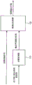
Fig. 1 shows an apparatus for generating one or more audio output channels according to an embodiment.
The device comprises a parameter processor 110 and a downmix processor 120, this parameter processor 110 being adapted to calculate output channel mixing information, and the downmix processor 120 being adapted to generate the one or more audio output channels.
The downmix processor 120 is configured to receive an audio transport signal comprising one or more audio transport channels, wherein two or more audio object signals are mixed in the audio transport signal, and wherein a number of the one or more audio transport channels is smaller than a number of the two or more audio object signals. The audio transmission signal depends on a first mixing rule and a second mixing rule. The first mixing rule indicates how to mix the two or more audio object signals to obtain a plurality of pre-mixed channels. Furthermore, the second mixing rule indicates how to mix the plurality of pre-mixed channels to obtain one or more audio transmission channels of the audio transmission signal.
The parameter processor 110 is configured to receive information of the second mixing rule, wherein the information of the second mixing rule indicates how to mix the plurality of pre-mixed signals such that the one or more audio transmission channels are obtained. The parameter processor 110 is configured to calculate the output channel mixing information according to a number of audio objects, a number of premixed channels, and information of the second mixing rule, the number of audio objects indicating the number of the two or more audio object signals, and the number of premixed channels indicating the number of the plurality of premixed channels.
The downmix processor 120 is configured to generate one or more audio output channels from the audio transmission signal based on the output channel mixing information.
According to an embodiment, the apparatus may e.g. be adapted to receive at least one of the number of audio objects and the number of pre-mixed channels.
In another embodiment, the parameter processor 110 may be configured to determine the information of the first mixing rule, for example, according to the number of audio objects and the number of pre-mixed channels, such that the information of the first mixing rule indicates how to mix the two or more audio object signals to obtain the plurality of pre-mixed channels. In this embodiment, the parameter processor 110 may calculate the output channel mixing information, such as information for the first mixing rule and information for the second mixing rule.
According to an embodiment, the parameter processor 110 may be configured to determine a plurality of coefficients of a first matrix P as the information of the first mixing rule, e.g. according to the number of audio objects and the number of pre-mixed channels, wherein the first matrix P indicates how to mix the plurality of pre-mixed channels to obtain the one or more audio transmission channels of the audio transmission signal. In this embodiment, the parameter processor 110 may be for example configured to receive a plurality of coefficients of a second matrix P as information of the second mixing rule, wherein the second matrix Q indicates how to mix the plurality of premixed channels to obtain the one or more audio transmission channels of the audio transmission signal. The parameter processor 110 of this embodiment may be configured to calculate the output channel mix information, for example, from the first matrix P and the second matrix Q.
Embodiments are based on the following findings: when down-mixing the two or more audio object signals X to obtain an audio transmission signal Y on the encoder side by employing a down-mixing matrix D according to the following formula,
Y=DX,
the downmix matrix D can then be divided into two smaller matrices P and Q according to the following formula:
D=QP。
thus, the first matrix P implements the audio object signals X to the plurality of pre-mixed channels X according to the formula pre Is a mixture of:
X pre =PX
the second matrix Q implements the data from the plurality of premixed channels X according to the following formula pre Mixing of one or more audio transmission channels to the audio transmission signal Y:
Y=Q X pre
according to this embodiment, information of the second mixing rule, such as information of the coefficients of the second mixing matrix Q, is transmitted to the decoder.
While the coefficients of the first mixing matrix P are not transmitted to the decoder. Instead, the decoder receives information of a plurality of audio object signals and information of a plurality of premixed channels. From this information, this decoder is able to reconstruct the first mixing matrix P. For example, whenMixing a first quantity of N objects To a second number N of audio object signals pre The encoder and decoder determine the mixing matrix P in the same manner.
Fig. 3 shows a system according to an embodiment. The system comprises means 310 for generating an audio transmission signal as described above with reference to fig. 2, and means 320 for generating one or more audio output channels as described above with reference to fig. 1.
The means 320 for generating one or more audio output channels is arranged to receive the audio transmission signal and the information of the second mixing rule from the means 310 for generating an audio transmission signal. Furthermore, the means 320 for generating one or more audio output channels is arranged to generate the one or more audio output channels from the audio transmission signal in accordance with the information of the second mixing rule.
For example, the parameter processor 110 may, e.g., be configured to receive metadata information including location information for each of the two or more audio object signals, and determine information for the first downmix rule based on the location information for each of the two or more audio object signals, e.g., by employing a vector-based amplitude phase shift. For example, the encoder may access positional information of each of two or more audio object signals, or vector-basis amplitude phase shifts may be used to determine weights of the audio object signals in the pre-mixed channel, while the decoder also determines coefficients of the first matrix P in the same manner (e.g., the encoder and decoder may use the same positioning of speakers assigned to N pre Each premixed channel).
By receiving the coefficients of the second matrix Q and determining the first matrix P, this decoder can determine the downmix matrix D from d=qp.
In an embodiment, the parameter processor 110 may, for example, be arranged to receive covariance information, such as coefficients of a covariance matrix E (e.g. from means for generating audio transmission signals), to indicate an object level difference for each of the two or more audio object signals, and possibly also to indicate one or more inter-object correlations between one of the audio object signals and another of the audio object signals.
In this embodiment, the parameter processor 110 may be configured to calculate the output channel mixing information according to the number of audio objects, the number of premixed channels, the information of the second mixing rule, and the covariance information.
For example, using the covariance matrix E, the audio object signal X may be reconstructed to obtain a reconstructed audio object using the following formula

Where G is the parameterized source estimation matrix, g= E D H (D E D H ) –1 。
Then, one or more audio output channels Z may be passed through the reconstructed audio object according to the following formula  The upper application rendering matrix R is generated according to the following formula:

however, the generation of the one or more audio output channels Z from the audio transmission signal can be performed in a single step using a matrix U according to the following formula:
z=uy, where s=ug.
This matrix S is an example for determining output channel mix information by the parameter processor 110.
For example, as explained above, each column of the rendering matrix R may be associated with one of the audio output channels to be generated. Each coefficient in one of the columns of the rendering matrix R determines the weight of one of the reconstructed audio object signals in the audio output channel to which that column of the rendering moment R is associated.
According to an embodiment, the parametric processor 110 may be configured to receive, for example, metadata information comprising position information for each of the two or more audio object signals, to determine rendering information, for example coefficients of a rendering matrix R, based on, for example, the position information of each of the two or more audio object signals, and to calculate the output channel mixing information (e.g. matrix S as described above) based on, for example, the number of audio objects, the number of pre-mixed channels, information of a second mixing rule, and the rendering information (e.g. rendering matrix R).
As such, the rendering matrix R may, for example, depend on the position information of each audio object signal transmitted to the SAOC decoder in the metadata information. E.g. audio object signals located close to the assumed or actual loudspeaker position, e.g. may have higher weights in the audio output channels of the loudspeakers than audio object signals located far from the loudspeakers (see fig. 5). For example, vector magnitude phase shifts may be used to determine the weights of the audio object signals in each audio output channel (e.g., please see [ VBAP ]). With respect to VBAP, it is assumed that audio object signals are assigned to virtual sources, and further that the audio output channels are channels of speakers. The corresponding coefficients of the rendering matrix R may be set according to such weights (this coefficient being assigned to the considered audio output channel and the audio object signal). For example, the weights themselves may be the values of the corresponding coefficients in the rendering matrix R.
Embodiments for implementing spatial down-mixing for object-based signals are described in detail below.
Reference is made to the following symbols and definitions:
N Objects number of input audio object signals
N ChannelsNumber of input channels
The number of N input signals, N may be equal to N Objects ,N Channels Or the sum of the two (N) Objects +N Channels )
N DmxCh Down-mix the number of (processed) channels
N pre Number of premixed channels
N Samples Number of processed data samples
D down-mix matrix of size N DmxCh x N
X comprises input audio signals of the two or more audio input signals, having a size NxN Samples
Y-down mixed audio signal (said audio transmission signal) of size N DmxCh x N Samples Defined as y=dx
DMG for down-mix gain data for each input signal, down-mix channel and parameter set
D DMG Is a three-dimensional matrix that holds dequantized mapped DMG data for each input signal, downmix channel, and parameter set.
Without loss of generality, the index representing time and frequency dependence is omitted for all introduced variables in order to improve the readability of the formula.
If no restrictions are specified for the input signal (channel or object), the downmix coefficients are calculated in the same way for the input channel signal as well as for the input object signal. The symbol N is used to represent the number of input signals.
Some implementations may, for example, be designed to down-mix the object signal in a different way than the channel signal, which is guided by spatial information available for the object metadata.
This downmix can be divided into two steps:
in a first step, the object is pre-rendered to a reproduction layout with the highest number of loudspeakers (e.g. N pre =22 is given by the 22.2 configuration), for example, the first matrix P may be employed.
-in a second stepThe N obtained pre The pre-rendered signal is down-mixed to a plurality of available transmission channels (N DmxCh ) (e.g., according to an orthogonal downmixing distribution algorithm). For example, the second matrix Q may be employed.
However, in some embodiments, this downmixing may be accomplished in a single step, e.g., by employing a method according to the formula: d=qp defines a matrix D and is defined by applying y=dx and d=qp.
In particular, a further advantage of the proposed concept is that, as in the audio scene, the input object signals rendered at the same spatial position are downmixed together in the same transmission channel. Therefore, at the decoder side, a preferred separation of the rendering signals can be obtained, and separation of audio objects mixed together in the final reproduction scene can be prevented.
According to a particularly preferred embodiment, the downmix can be described as a matrix multiplication by:
X pre =px and y=qx pre
Wherein the size of P (N pre x N Objects ) Size of Q (N DmxCh x N pre ) Can be calculated as follows.
The mixing coefficients in P are constructed from object signal metadata (radius, gain, azimuth and elevation) using a phase shift algorithm (e.g., vector-based amplitude phase shift). The panning algorithm should be the same as the panning algorithm used at the decoder side to construct the output channels.
The mixing coefficients given in Q at the encoder side are for N pre Input signals and N DmxCh Available transmission channels.
To reduce computational complexity, the two-step downmix can be reduced to one step by calculating the final downmix gain, such as:
D=QP
the downmix signal is then given by:
Y=DX
the mixing coefficients in P will not be transmitted in the bitstream. Instead, the hybrid coefficients are reconstructed at the decoder side using the same translation algorithm. Thus, the bit rate can be reduced by transmitting only the mix coefficients in Q. In particular, when the mixing coefficients in P are typically time-variant, and when P is not transmitted, a higher bit rate reduction can be achieved.
Hereinafter, according to an embodiment, the bitstream syntax is considered.
The MPEG SAOC bitstream syntax is expanded to use 4 bits in order to signal the downmix method used and the number Npre of channels to pre-render the objects in the first step:

bsNumPremixedChannels
| bsSaocDmxMethod | bsNumPremixedChannels |
| 0 | 0 |
| 1 | 22 |
| 2 | 11 |
| 3 | 10 |
| 4 | 8 |
| 5 | 7 |
| 6 | 5 |
| 7 | 2 |
| 8,...,14 | Reserved for |
| 15 | Escape value |
In the context of MPEG SAOC, this can be done by the following modifications:
bsSaocDmxMethod, indicating how the downmix matrix is constructed
Syntax of SAOC3 dspecconficconfig (): signaling

bsnumsaoc dmxchannels defines the number of downmix channels for channel-based content. If there are no channels in the downmix, bsNumSaocDmxChannels is set to 0
bsNumSaocChannels defines the number of input channels used to transmit SAOC three-dimensional parameters. If bsNumSaocChannels is equal to 0, then there are no channels in the downmix
bsNumSaocDmxObjects define the number of downmix channels for object-based content. If there are no objects in the downmix, bsNumSaocDmxObjects are set to 0
bsNumPremixedChannels defines the number of premixed channels for input audio objects. If bsSaocDmxMethod is equal to 15, the actual number of premixed channels is signaled directly by the value of bsNumPremixedChannels. In all other cases bsNumPremixedChannels is set according to the previous table.
According to an embodiment, the downmix matrix D applied to the input audio signal S determines the downmix signal as:
X=DS
Size N dmx The downmix matrix of x N can be obtained by the following formula:
D=D dmx D premix
according to the processing mode, the matrix D dmx Matrix D premix Having different sizes.
The matrix D dmx Obtained from the DMG parameters, can be expressed as:

here, the dequantized downmix parameters may be obtained by:
DMG i,j =D DMG (i,j,l)
in the case of direct mode, no premixing is used. The matrix D premix Has a size of n×n, and this matrix can be represented by: d (D) premix =i. The matrix D dmx Having N dmx The size of x N, and it is obtained from DMG parameters.
In the case of premix mode, the matrix D premix Has a size (N) ch +N premix ) X N, and this matrix can be represented by:

wherein from the object renderer, the size is N premix ×N obj Is received as input to the SAOC three-dimensional decoder.
The matrix D dmx Having N premix ×N obj And it is obtained from the DMG parameters.
Although some aspects have been described in the context of apparatus, it is clear that these aspects also represent descriptions of corresponding methods, whereas blocks or apparatus correspond to method steps or features of method steps. Likewise, aspects described in the context of method steps also represent descriptions of corresponding blocks or items or features of corresponding devices.
The decompressed signals of the present invention may be stored on a digital storage medium or may be transmitted to a transmission medium, such as a wireless transmission medium or a wired transmission medium (e.g., the internet).
Embodiments of the invention may be implemented in hardware or in software, depending on the particular execution requirements. This implementation may be implemented using a digital storage medium, such as a floppy disk, DVD, CD, ROM, PROM, EPROM, EEPROM, or FLASH memory, storing electronically readable control signals, which can cooperate (or be able to cooperate) with a programmable computer system to perform the method described above.
Some embodiments according to the invention comprise a non-transitory data carrier with electronically readable control signals, which can be co-ordinated with a programmable computer system, to perform one of the methods described above.
In general, embodiments of the invention may be implemented as a computer program product having a program code operable to perform one of the methods described above when the computer program product is run on a computer. For example, the program code may be stored on a machine readable carrier.
Other embodiments include a computer program for performing one of the methods described above, stored on a machine-readable carrier.
In other words, an embodiment of the method of the invention is thus a computer program with a program code capable of executing one of the above methods when this computer program is run on a computer.
Thus, another embodiment of the method of the present invention is a data carrier (or digital storage medium or computer readable medium) comprising a computer program recorded thereon for performing one of the methods described above.
Thus, another embodiment of the method of the present invention is a data stream or signal sequence representing a computer program for performing one of the above methods. For example, the data stream or signal sequence may be configured to be transmitted via a data communication connection, for example via the internet.
Another embodiment comprises a processing means, such as a computer, or a programmable logic device, for or adapted to perform one of the above methods.
Another embodiment comprises a computer installed with a computer program for performing one of the methods described above.
According to an embodiment of the present invention, there is provided an apparatus for generating one or more audio output channels, wherein the apparatus comprises: a parameter processor (110) for calculating output channel mixing information, and a downmix processor (120) for generating the one or more audio output channels, wherein the downmix processor (120) is for receiving an audio transmission signal comprising one or more audio transmission channels, wherein two or more audio object signals are mixed in the audio transmission signal, and wherein a number of the one or more audio transmission channels is smaller than a number of the two or more audio object signals, wherein the audio transmission signal depends on a first mixing rule and a second mixing rule, wherein the first mixing rule indicates how to mix the two or more audio object signals to obtain a plurality of premixed channels, and wherein the second mixing rule indicates how to mix the one or more audio transmission channels of the plurality of premixed channels to obtain the audio transmission signal, wherein the parameter processor (110) is for receiving information of the second mixing rule, wherein the information of the second mixing rule indicates how to mix the plurality of audio object signals, and a second mixing rule indicates how to mix the one or more audio object signals, the number of the one or more audio object signals being calculated according to the number of the first mixing rule indicates how to mix the one or more audio object signals to obtain the plurality of premixed channels, and wherein the downmix processor (120) is configured to generate the one or more audio output channels from the audio transmission signal in accordance with the output channel mixing information.
According to an embodiment of the invention, the means are for receiving at least one of said number of audio objects and said number of pre-mixed channels.
According to an embodiment of the invention, wherein the parameter processor (110) is adapted to determine information of the first mixing rule based on the number of audio objects and the number of pre-mixed channels, such that the information of the first mixing rule indicates how to mix the two or more audio object signals to obtain the plurality of pre-mixed channels, and wherein the parameter processor (110) is adapted to calculate the output channel mixing information based on the information of the first mixing rule and the information of the second mixing rule.
According to an embodiment of the invention, wherein the parameter processor (110) is configured to determine a plurality of coefficients of a first matrix (P) as the information of the first mixing rule based on the number of audio objects and the number of pre-mixed channels, wherein the first matrix (P) is indicative of how to mix the plurality of pre-mixed channels to obtain the one or more audio transmission channels of the audio transmission signal, wherein the parameter processor (110) is configured to receive a plurality of coefficients of a second matrix (Q) as the information of the second mixing rule, wherein the second matrix (Q) is indicative of how to mix the plurality of pre-mixed channels to obtain the one or more audio transmission channels of the audio transmission signal, and wherein the parameter processor (110) is configured to calculate the output channel mixing information based on the first matrix (P) and the second matrix (Q).
According to an embodiment of the invention, wherein the parameter processor (110) is adapted to receive metadata information comprising position information for each of the two or more audio object signals, wherein the parameter processor (110) is adapted to determine the information of the first downmix rule from the position information of each of the two or more audio object signals.
According to an embodiment of the invention, wherein the parameter processor (110) is adapted to determine rendering information from the position information of each of the two or more audio object signals, and wherein the parameter processor (110) is adapted to calculate the output channel mix information from the number of audio objects, the number of pre-mixed channels, the information of the second mixing rule and the rendering information.
According to an embodiment of the invention, wherein the parameter processor (110) is adapted to receive covariance information indicating an object level difference for each of the two or more audio object signals, and wherein the parameter processor (110) is adapted to calculate the output channel mix information from the number of audio objects, the number of pre-mixed channels, the information of the second mixing rule, and the covariance information.
According to an embodiment of the invention, wherein the covariance information further indicates at least one inter-object correlation between one of the two or more audio object signals and the other, and wherein the parameter processor (110) is configured to calculate the output channel mix information based on the number of audio objects, the number of pre-mix channels, the information of the second mixing rule, the object level difference of each of the two or more audio object signals, and the at least one inter-object correlation between one of the two or more audio object signals and the other.
According to an embodiment of the present invention, there is provided a device for generating an audio transmission signal comprising one or more audio transmission channels, wherein the device comprises: -an object mixer (210) for generating the audio transmission signal comprising the one or more audio transmission channels from two or more audio object signals such that the two or more audio object signals are mixed in the audio transmission signal, and wherein the number of the one or more audio transmission channels is smaller than the number of the two or more audio object signals, and-an output interface (220) for outputting the audio transmission signal, wherein the object mixer (210) is for generating the one or more audio transmission channels of the audio transmission signal according to a first mixing rule and a second mixing rule, wherein the first mixing rule indicates how to mix the two or more audio object signals to obtain a plurality of pre-mixed channels, and wherein the second mixing rule indicates how to mix the plurality of pre-mixed channels to obtain the one or more audio transmission channels of the audio transmission signal, and wherein the first mixing rule is dependent on a number of audio and a number of pre-mixed channels, and the number of pre-mixed channels is dependent on the number of the second mixing rule indicates the number of the one or more pre-mixed channels and the number of pre-mixed channels is outputted according to the second mixing rule (220).
According to an embodiment of the invention, wherein the object mixer (210) is adapted to generate the one or more audio transmission channels of the audio transmission signal according to a first matrix (P) and a second matrix (Q), wherein the first matrix (P) is indicative of how to mix the plurality of premixed channels to obtain the one or more audio transmission channels of the audio transmission signal, and the second matrix (Q) is indicative of how to mix the plurality of premixed channels to obtain the one or more audio transmission channels of the audio transmission signal, and wherein the parameter processor (110) is adapted to output a plurality of coefficients of the second matrix (Q) as the information of the second mixing rule.
According to an embodiment of the invention, wherein the object mixer (210) is arranged to receive position information for each of the two or more audio object signals, and wherein the object mixer (210) is arranged to determine the first mixing rule based on the position information for each of the two or more audio object signals.
According to an embodiment of the present invention, there is provided a system including: a device (310) for generating an audio transmission signal according to an embodiment of the invention, and a device (320) for generating one or more audio output channels according to an embodiment of the invention, wherein the device (320) is arranged to receive information of the audio transmission signal and the second mixing rule from the device (310), and wherein the device (320) is arranged to generate the one or more audio output channels from the audio transmission signal based on the information of the second mixing rule.
According to an embodiment of the present invention, there is provided a method for generating one or more audio output channels, wherein the method comprises: receiving an audio transmission signal comprising one or more audio transmission channels, wherein two or more audio object signals are mixed in the audio transmission signal, and wherein the number of the one or more audio transmission channels is smaller than the number of the two or more audio object signals, wherein the audio transmission signal depends on a first mixing rule indicating how to mix the two or more audio object signals to obtain a plurality of premixed channels, and a second mixing rule indicating how to mix the plurality of premixed channels to obtain the one or more audio transmission channels of the audio transmission signal, wherein the information of the second mixing rule indicates how to mix the plurality of premixed signals such that the one or more audio transmission channels are obtained, calculating output mixing information according to a first mixing rule indicating how to mix the two or more audio object signals to obtain the plurality of premixed channels, and information of the second mixing rule indicating how to mix the plurality of audio object signals, the number of premixed channels and the output mixing information indicating how to generate the plurality of audio transmission channels from the one or more audio transmission channels according to the number of the plurality of premixed channels.
According to an embodiment of the present invention, there is provided a method of generating an audio transmission signal comprising one or more audio transmission channels, wherein the method comprises: generating the audio transmission signal from two or more audio object signals, the audio transmission signal comprising the number of the one or more audio transmission channels, outputting the audio transmission signal, and outputting information of the second mixing rule, wherein generating the audio transmission signal from two or more audio object signals is performed such that the two or more audio object signals are mixed in the audio transmission signal, the audio transmission signal comprising the one or more audio transmission channels, wherein the number of the one or more audio transmission channels is smaller than the number of the two or more audio object signals, and wherein generating the one or more audio transmission channels of the audio transmission signal is performed according to a first mixing rule and a second mixing rule, wherein the first mixing rule indicates how to mix the two or more audio object signals to obtain a plurality of pre-mixed audio signals, the second mixing rule indicates how to mix the plurality of pre-mixed audio transmission channels to obtain the plurality of pre-mixed audio transmission channels, wherein the number of the one or more audio object signals is smaller than the number of the two or more audio transmission channels, the number of pre-mixed audio object signals is dependent on the number of the one or more pre-mixed audio object signals, and the number of the one or more pre-mixed audio transmission channels is dependent on the number of the one or more pre-mixed object signals.
According to an embodiment of the present invention, a computer program is provided for implementing a method for generating one or more audio output channels or a method for generating an audio transmission signal comprising one or more audio transmission channels as described in an embodiment of the present invention, when the computer program is executed on a computer or a signal processor.
In some embodiments, a programmable logic device (e.g., a field programmable gate array) may be used to perform some or all of the functions of the methods described above. In some embodiments, a field programmable gate array may cooperate with a microprocessor in order to perform one of the methods described above. In general, this method may be preferably performed by any hardware device.
The above-described embodiments are merely illustrative of the principles of the present invention. It is to be understood that modifications and variations and details of the arrangements described herein will be apparent to other persons skilled in the art. It is therefore intended that the scope of the impending patent claims be limited not by the specific details presented by way of the embodiments and illustrations described herein.
Reference is made to:
[ SAOC1] J.Herre, S.Disch, J.Hilpert, O.Hellmuth, "From SAC To SAOC-Recent Developments in Parametric Coding of Spatial Audio", month 4 of 22nd Regional UK AES Conference,Cambridge,UK,2007.
[SAOC2]J. B.Resch,C.Falch,O.Hellmuth,J.Hilpert,A./>
 L.Terentiev,J.Breebaart,J.Koppens,E.Schuijers and W.Oomen:"Spatial Audio Object Coding(SAOC)–The Upcoming MPEG Standard on Parametric Object Based Audio Coding",124th AES Convention,Amsterdam 2008.
[SAOC]ISO/IEC,“MPEG audio technologies–Part 2:Spatial Audio Object Coding(SAOC),”ISO/IEC JTC1/SC29/WG11(MPEG)International Standard 23003-2.
[ VBAP ] Ville Pulkki, "Virtual Sound Source Positioning Using Vector Base Amplitude Panning"; audio eng.Soc., level 45, 6, pages 456-466, month 6 1997.
[ M1] Peters, N., lossius, T.and Schacher J.C., spatDIF: principles, specification, and samples ",9th Sound and Music Computing Conference,Copenhagen,Denmark,2012, 7 months.
[M2]Wright,M.,Freed,A.,"Open Sound Control:A New Protocol for Communicating with Sound Synthesizers",International Computer Music Conference,Thessaloniki,Greece,1997.
[ M3] Matthias Geier, jens Ahrens, and Sascha Spors. (2010), "Object-based audio reproduction and the audio scene description format", org. Sound, vol.15, vol.3, pages 219-227, month 12 of 2010.
[ M4] W3C, "Synchronized Multimedia Integration Language (SMIL 3.0)", month 12 of 2008.
[ M5] W3C, "Extensible Markup Language (XML) 1.0 (Fifth Edition)", month 11 of 2008.
[M6]MPEG,"ISO/IEC International Standard 14496-3-Coding of audio-visual objects,Part 3 Audio",2009.
[ M7] Schmidt, J.; schroeder, E.F. (2004), "New and Advanced Features for Audio Presentation in the MPEG-4Standard", month 5 of 116th AES Convention,Berlin,Germany,2004.
[M8]Web3D,"International Standard ISO/IEC 14772-1:1997-The Virtual Reality Modeling Language(VRML),Part 1:Functional specification and UTF-8encoding",1997.
[M9]Sporer,T.(2012),"Codierung Audiosignale mit leichtgewichtigen Audio-Objekten ", proc.Annual Meeting of the German Audiological Society (DGA), erlangen, germany, 3 nd 2012>
Claims (17)
1. A device for generating one or more audio output channels, wherein the device comprises:
A parameter processor (110) for calculating output channel mix information, and
a downmix processor (120) for generating one or more audio output channels from an audio transmission signal comprising the one or more audio transmission channels, wherein two or more audio object signals are mixed in the audio transmission signal, wherein a number of the one or more audio transmission channels is smaller than a number of the two or more audio object signals, based on the output channel mixing information,
wherein the audio transmission signal depends on the first mixed information and the second mixed information, and
wherein the parameter processor (110) is configured to calculate the output channel mix information based on a number of audio objects, a number of pre-mix channels, and information of the second mix information, the number of audio objects being indicative of the number of the two or more audio object signals.
2. The apparatus of claim 1,
wherein the audio transmission signal depends on a first mixing information and a second mixing information, wherein the first mixing information indicates how to mix the two or more audio object signals to obtain a plurality of pre-mixed channels, and wherein the second mixing information indicates how to mix the plurality of pre-mixed channels to obtain the one or more audio transmission channels of the audio transmission signal, an
Wherein the parameter processor (110) is configured to receive the information of the second mixing information, wherein the information of the second mixing information indicates how to mix the plurality of pre-mixed channels such that the one or more audio transmission channels are obtained.
3. The apparatus of claim 2, wherein the device comprises a plurality of sensors,
wherein the parameter processor (110) is configured to calculate the output channel mix information based on a number of audio objects indicating a number of the two or more audio object signals, a number of pre-mixed channels indicating the number of the plurality of pre-mixed channels, and the information of the second mix information.
4. An apparatus according to claim 3,
wherein the parameter processor (110) is configured to determine information of the first mixing information based on the number of audio objects and the number of pre-mixed channels, such that the information of the first mixing information indicates how to mix the two or more audio object signals to obtain the plurality of pre-mixed channels, an
Wherein the parameter processor (110) is configured to calculate the output channel mix information based on the information of the first mix information and the information of the second mix information.
5. The apparatus according to claim 4,
wherein the parameter processor (110) is configured to determine a plurality of coefficients of a first matrix (P) as the information of the first mixing information, based on the number of audio objects and the number of pre-mixed channels, wherein the first matrix (P) indicates how to mix the plurality of pre-mixed channels to obtain the one or more audio transmission channels of the audio transmission signal,
wherein the parameter processor (110) is configured to receive a plurality of coefficients of a second matrix (Q) as the information of the second mixing information, wherein the second matrix (Q) indicates how to mix the plurality of pre-mixed channels to obtain the one or more audio transmission channels of the audio transmission signal, and
wherein the parameter processor (110) is configured to calculate the output channel mix information from the first matrix (P) and the second matrix (Q).
6. The apparatus of claim 1,
wherein the parameter processor (110) is adapted to receive metadata information comprising position information for each of the two or more audio object signals,
wherein the parameter processor (110) is configured to determine the information of the first mixing information based on the position information of each of the two or more audio object signals.
7. The apparatus of claim 6, wherein the device comprises a plurality of sensors,
wherein the parameter processor (110) is configured to determine rendering information based on the position information of each of the two or more audio object signals, and
wherein the parameter processor (110) is configured to calculate the output channel mix information based on the number of audio objects, the number of pre-mixed channels, the information of the second mix information, and the rendering information.
8. The apparatus of claim 1,
wherein the parameter processor (110) is configured to receive covariance information indicating an object level difference for each of the two or more audio object signals, an
Wherein the parameter processor (110) is configured to calculate the output channel mix information based on the number of audio objects, the number of pre-mixed channels, the information of the second mix information, and the covariance information.
9. The apparatus of claim 8,
wherein the covariance information further indicates at least one inter-object correlation between one and the other of the two or more audio object signals, an
Wherein the parameter processor (110) is configured to calculate the output channel mix information based on the number of audio objects, the number of pre-mix channels, the information of the second mix information, the object level difference of each of the two or more audio object signals, and the at least one inter-object correlation between one and the other of the two or more audio object signals.
10. A device for generating an audio transmission signal comprising one or more audio transmission channels, wherein the device comprises:
an object mixer (210) for generating from two or more audio object signals the audio transmission signal comprising the one or more audio transmission channels such that the two or more audio object signals are mixed in the audio transmission signal, an
An output interface (220) for outputting the audio transmission signal,
wherein the object mixer (210) is configured to generate the one or more audio transmission channels of the audio transmission signal based on first mixing information and second mixing information, wherein the first mixing information indicates how to mix the two or more audio object signals to obtain a plurality of pre-mixed channels, and wherein the second mixing information indicates how to mix the plurality of pre-mixed channels to obtain the one or more audio transmission channels of the audio transmission signal, wherein a number of the one or more audio transmission channels is smaller than a number of the two or more audio object signals.
11. The apparatus of claim 10,
wherein the first mixing information is dependent on a number of audio objects indicating the number of the two or more audio object signals and a number of pre-mix channels indicating the number of the plurality of pre-mix channels, and wherein the second mixing information is dependent on the number of pre-mix channels.
12. The apparatus of claim 11,
wherein the object mixer (210) is configured to generate the one or more audio transmission channels of the audio transmission signal according to a first matrix (P) and a second matrix (Q), wherein the first matrix (P) is indicative of how to mix the plurality of pre-mixed channels to obtain the one or more audio transmission channels of the audio transmission signal, and the second matrix (Q) is indicative of how to mix the plurality of pre-mixed channels to obtain the one or more audio transmission channels of the audio transmission signal, and
wherein the object mixer (210) is configured to output a plurality of coefficients of the second matrix (Q) as the information of the second mixing information.
13. The apparatus of claim 10,
wherein the object mixer (210) is configured to receive position information for each of the two or more audio object signals, and
wherein the object mixer (210) is configured to determine the first mixing information based on the position information of each of the two or more audio object signals.
14. A system for generating one or more audio output channels, comprising:
the apparatus (310) for generating an audio transmission signal comprising one or more audio transmission channels as claimed in claim 10, and
The apparatus (320) for generating one or more audio output channels according to claim 1,
wherein the apparatus (320) of claim 1 is configured to receive information of the audio transmission signal and the second mixing information from the apparatus (310) of claim 11, and
the apparatus (320) of claim 1, wherein the one or more audio output channels are generated from the audio transmission signal based on the information of the second mixing information.
15. A method for generating one or more audio output channels, wherein the method comprises:
calculating output channel mix information
Generating one or more audio output channels from an audio transmission signal comprising one or more audio transmission channels, wherein two or more audio object signals are mixed in the audio transmission signal, wherein the number of the one or more audio transmission channels is smaller than the number of the two or more audio object signals,
wherein the audio transmission signal is dependent on the first mixing information and the second mixing information,
wherein calculating the output channel mix information is performed based on a number of audio objects, a number of pre-mixed channels, and information of the second mix information, the number of audio objects indicating the number of the two or more audio object signals, and
Wherein generating the one or more audio output channels from the audio transmission signal is performed in accordance with the output channel mixing information.
16. A method of generating an audio transmission signal comprising one or more audio transmission channels, wherein the method comprises:
generating the audio transmission signal from two or more audio object signals such that the two or more audio object signals are mixed in the audio transmission signal, the audio transmission signal comprising the one or more audio transmission channels,
outputting the audio transmission signal
The information is output and the information is output,
wherein the one or more audio transmission channels of the audio transmission signal are generated according to a first mixing information and a second mixing information, wherein the first mixing information indicates how to mix the two or more audio object signals to obtain a plurality of pre-mixed channels, and wherein the second mixing information indicates how to mix the plurality of pre-mixed channels to obtain the one or more audio transmission channels of the audio transmission signal, wherein the number of the one or more audio transmission channels is smaller than the number of the two or more audio object signals.
17. A computer readable medium comprising a computer program for implementing the method of claim 15 or 16 when the computer program is executed on a computer or signal processor.
Priority Applications (1)
| Application Number | Priority Date | Filing Date | Title |
|---|---|---|---|
| CN202011323152.7A CN112839296B (en) | 2013-07-22 | 2014-07-16 | Apparatus and method for implementing SAOC down-mixing of 3D audio content |
Applications Claiming Priority (11)
| Application Number | Priority Date | Filing Date | Title |
|---|---|---|---|
| EP13177371.5 | 2013-07-22 | ||
| EP20130177378 EP2830045A1 (en) | 2013-07-22 | 2013-07-22 | Concept for audio encoding and decoding for audio channels and audio objects |
| EP13177357.4 | 2013-07-22 | ||
| EP13177371 | 2013-07-22 | ||
| EP13177357 | 2013-07-22 | ||
| EP13177378.0 | 2013-07-22 | ||
| EP13189281.2A EP2830048A1 (en) | 2013-07-22 | 2013-10-18 | Apparatus and method for realizing a SAOC downmix of 3D audio content |
| EP13189281.2 | 2013-10-18 | ||
| PCT/EP2014/065290 WO2015010999A1 (en) | 2013-07-22 | 2014-07-16 | Apparatus and method for realizing a saoc downmix of 3d audio content |
| CN201480041327.1A CN105593929B (en) | 2013-07-22 | 2014-07-16 | Device and method for realizing SAOC (save audio over coax) downmix of 3D (three-dimensional) audio content |
| CN202011323152.7A CN112839296B (en) | 2013-07-22 | 2014-07-16 | Apparatus and method for implementing SAOC down-mixing of 3D audio content |
Related Parent Applications (1)
| Application Number | Title | Priority Date | Filing Date |
|---|---|---|---|
| CN201480041327.1A Division CN105593929B (en) | 2013-07-22 | 2014-07-16 | Device and method for realizing SAOC (save audio over coax) downmix of 3D (three-dimensional) audio content |
Publications (2)
| Publication Number | Publication Date |
|---|---|
| CN112839296A CN112839296A (en) | 2021-05-25 |
| CN112839296B true CN112839296B (en) | 2023-05-09 |
Family
ID=49385153
Family Applications (3)
| Application Number | Title | Priority Date | Filing Date |
|---|---|---|---|
| CN201480041327.1A Active CN105593929B (en) | 2013-07-22 | 2014-07-16 | Device and method for realizing SAOC (save audio over coax) downmix of 3D (three-dimensional) audio content |
| CN202011323152.7A Active CN112839296B (en) | 2013-07-22 | 2014-07-16 | Apparatus and method for implementing SAOC down-mixing of 3D audio content |
| CN201480041467.9A Active CN105593930B (en) | 2013-07-22 | 2014-07-17 | The device and method that Spatial Audio Object for enhancing encodes |
Family Applications Before (1)
| Application Number | Title | Priority Date | Filing Date |
|---|---|---|---|
| CN201480041327.1A Active CN105593929B (en) | 2013-07-22 | 2014-07-16 | Device and method for realizing SAOC (save audio over coax) downmix of 3D (three-dimensional) audio content |
Family Applications After (1)
| Application Number | Title | Priority Date | Filing Date |
|---|---|---|---|
| CN201480041467.9A Active CN105593930B (en) | 2013-07-22 | 2014-07-17 | The device and method that Spatial Audio Object for enhancing encodes |
Country Status (19)
| Country | Link |
|---|---|
| US (4) | US9699584B2 (en) |
| EP (4) | EP2830050A1 (en) |
| JP (3) | JP6395827B2 (en) |
| KR (2) | KR101774796B1 (en) |
| CN (3) | CN105593929B (en) |
| AU (2) | AU2014295270B2 (en) |
| BR (2) | BR112016001244B1 (en) |
| CA (2) | CA2918529C (en) |
| ES (2) | ES2768431T3 (en) |
| HK (1) | HK1225505A1 (en) |
| MX (2) | MX355589B (en) |
| MY (2) | MY176990A (en) |
| PL (2) | PL3025333T3 (en) |
| PT (1) | PT3025333T (en) |
| RU (2) | RU2666239C2 (en) |
| SG (2) | SG11201600460UA (en) |
| TW (2) | TWI560701B (en) |
| WO (2) | WO2015010999A1 (en) |
| ZA (1) | ZA201600984B (en) |
Families Citing this family (22)
| Publication number | Priority date | Publication date | Assignee | Title |
|---|---|---|---|---|
| TWI603321B (en) | 2015-02-02 | 2017-10-21 | 弗勞恩霍夫爾協會 | Apparatus and method for processing an encoded audio signal |
| CN106303897A (en) | 2015-06-01 | 2017-01-04 | 杜比实验室特许公司 | Process object-based audio signal |
| MX365274B (en) * | 2015-06-17 | 2019-05-29 | Sony Corp | Transmission device, transmission method, reception device and reception method. |
| WO2017209477A1 (en) * | 2016-05-31 | 2017-12-07 | 지오디오랩 인코포레이티드 | Audio signal processing method and device |
| US10349196B2 (en) * | 2016-10-03 | 2019-07-09 | Nokia Technologies Oy | Method of editing audio signals using separated objects and associated apparatus |
| US10535355B2 (en) | 2016-11-18 | 2020-01-14 | Microsoft Technology Licensing, Llc | Frame coding for spatial audio data |
| CN108182947B (en) * | 2016-12-08 | 2020-12-15 | 武汉斗鱼网络科技有限公司 | Sound channel mixing processing method and device |
| JP7230799B2 (en) * | 2017-03-28 | 2023-03-01 | ソニーグループ株式会社 | Information processing device, information processing method, and program |
| TWI703557B (en) * | 2017-10-18 | 2020-09-01 | 宏達國際電子股份有限公司 | Sound reproducing method, apparatus and non-transitory computer readable storage medium thereof |
| GB2574239A (en) * | 2018-05-31 | 2019-12-04 | Nokia Technologies Oy | Signalling of spatial audio parameters |
| US10620904B2 (en) | 2018-09-12 | 2020-04-14 | At&T Intellectual Property I, L.P. | Network broadcasting for selective presentation of audio content |
| US20210348028A1 (en) | 2018-09-28 | 2021-11-11 | Fujimi Incorporated | Composition for polishing gallium oxide substrate |
| GB2577885A (en) * | 2018-10-08 | 2020-04-15 | Nokia Technologies Oy | Spatial audio augmentation and reproduction |
| GB2582748A (en) * | 2019-03-27 | 2020-10-07 | Nokia Technologies Oy | Sound field related rendering |
| US11622219B2 (en) * | 2019-07-24 | 2023-04-04 | Nokia Technologies Oy | Apparatus, a method and a computer program for delivering audio scene entities |
| GB2587614A (en) * | 2019-09-26 | 2021-04-07 | Nokia Technologies Oy | Audio encoding and audio decoding |
| EP4120250A4 (en) * | 2020-03-09 | 2024-03-27 | Nippon Telegraph & Telephone | Sound signal downmixing method, sound signal coding method, sound signal downmixing device, sound signal coding device, program, and recording medium |
| GB2595475A (en) * | 2020-05-27 | 2021-12-01 | Nokia Technologies Oy | Spatial audio representation and rendering |
| JP2022083445A (en) | 2020-11-24 | 2022-06-03 | ネイバー コーポレーション | Computer system for producing audio content for achieving user-customized being-there and method thereof |
| KR102508815B1 (en) | 2020-11-24 | 2023-03-14 | 네이버 주식회사 | Computer system for realizing customized being-there in assocation with audio and method thereof |
| JP2022083443A (en) * | 2020-11-24 | 2022-06-03 | ネイバー コーポレーション | Computer system for achieving user-customized being-there in association with audio and method thereof |
| WO2023131398A1 (en) * | 2022-01-04 | 2023-07-13 | Fraunhofer-Gesellschaft zur Förderung der angewandten Forschung e.V. | Apparatus and method for implementing versatile audio object rendering |
Citations (1)
| Publication number | Priority date | Publication date | Assignee | Title |
|---|---|---|---|---|
| CN101617360A (en) * | 2006-09-29 | 2009-12-30 | 韩国电子通信研究院 | Be used for equipment and method that Code And Decode has the multi-object audio signal of various sound channels |
Family Cites Families (78)
| Publication number | Priority date | Publication date | Assignee | Title |
|---|---|---|---|---|
| US2605361A (en) | 1950-06-29 | 1952-07-29 | Bell Telephone Labor Inc | Differential quantization of communication signals |
| JP3576936B2 (en) | 2000-07-21 | 2004-10-13 | 株式会社ケンウッド | Frequency interpolation device, frequency interpolation method, and recording medium |
| US7720230B2 (en) | 2004-10-20 | 2010-05-18 | Agere Systems, Inc. | Individual channel shaping for BCC schemes and the like |
| SE0402651D0 (en) | 2004-11-02 | 2004-11-02 | Coding Tech Ab | Advanced methods for interpolation and parameter signaling |
| SE0402652D0 (en) | 2004-11-02 | 2004-11-02 | Coding Tech Ab | Methods for improved performance of prediction based multi-channel reconstruction |
| SE0402649D0 (en) * | 2004-11-02 | 2004-11-02 | Coding Tech Ab | Advanced methods of creating orthogonal signals |
| BRPI0608756B1 (en) | 2005-03-30 | 2019-06-04 | Koninklijke Philips N. V. | MULTICHANNEL AUDIO DECODER, A METHOD FOR CODING AND DECODING A N CHANNEL AUDIO SIGN, MULTICHANNEL AUDIO SIGNAL CODED TO AN N CHANNEL AUDIO SIGN AND TRANSMISSION SYSTEM |
| US8346564B2 (en) | 2005-03-30 | 2013-01-01 | Koninklijke Philips Electronics N.V. | Multi-channel audio coding |
| US7548853B2 (en) | 2005-06-17 | 2009-06-16 | Shmunk Dmitry V | Scalable compressed audio bit stream and codec using a hierarchical filterbank and multichannel joint coding |
| CN101288115A (en) * | 2005-10-13 | 2008-10-15 | Lg电子株式会社 | Method and apparatus for signal processing |
| KR100888474B1 (en) | 2005-11-21 | 2009-03-12 | 삼성전자주식회사 | Apparatus and method for encoding/decoding multichannel audio signal |
| JP4966981B2 (en) * | 2006-02-03 | 2012-07-04 | 韓國電子通信研究院 | Rendering control method and apparatus for multi-object or multi-channel audio signal using spatial cues |
| DE602007004451D1 (en) | 2006-02-21 | 2010-03-11 | Koninkl Philips Electronics Nv | AUDIO CODING AND AUDIO CODING |
| US7720240B2 (en) * | 2006-04-03 | 2010-05-18 | Srs Labs, Inc. | Audio signal processing |
| US8027479B2 (en) * | 2006-06-02 | 2011-09-27 | Coding Technologies Ab | Binaural multi-channel decoder in the context of non-energy conserving upmix rules |
| TWI371694B (en) | 2006-06-29 | 2012-09-01 | Lg Electronics Inc | Method and apparatus for an audio signal processing |
| EP2036201B1 (en) | 2006-07-04 | 2017-02-01 | Dolby International AB | Filter unit and method for generating subband filter impulse responses |
| JP5238706B2 (en) * | 2006-09-29 | 2013-07-17 | エルジー エレクトロニクス インコーポレイティド | Method and apparatus for encoding / decoding object-based audio signal |
| US9565509B2 (en) * | 2006-10-16 | 2017-02-07 | Dolby International Ab | Enhanced coding and parameter representation of multichannel downmixed object coding |
| AU2007322488B2 (en) * | 2006-11-24 | 2010-04-29 | Lg Electronics Inc. | Method for encoding and decoding object-based audio signal and apparatus thereof |
| WO2008069597A1 (en) | 2006-12-07 | 2008-06-12 | Lg Electronics Inc. | A method and an apparatus for processing an audio signal |
| EP2097895A4 (en) * | 2006-12-27 | 2013-11-13 | Korea Electronics Telecomm | Apparatus and method for coding and decoding multi-object audio signal with various channel including information bitstream conversion |
| CN101542595B (en) * | 2007-02-14 | 2016-04-13 | Lg电子株式会社 | For the method and apparatus of the object-based sound signal of Code And Decode |
| JP2010506232A (en) | 2007-02-14 | 2010-02-25 | エルジー エレクトロニクス インコーポレイティド | Method and apparatus for encoding and decoding object-based audio signal |
| RU2406165C2 (en) | 2007-02-14 | 2010-12-10 | ЭлДжи ЭЛЕКТРОНИКС ИНК. | Methods and devices for coding and decoding object-based audio signals |
| EP2137726B1 (en) | 2007-03-09 | 2011-09-28 | LG Electronics Inc. | A method and an apparatus for processing an audio signal |
| KR20080082917A (en) * | 2007-03-09 | 2008-09-12 | 엘지전자 주식회사 | A method and an apparatus for processing an audio signal |
| WO2008114982A1 (en) * | 2007-03-16 | 2008-09-25 | Lg Electronics Inc. | A method and an apparatus for processing an audio signal |
| US7991622B2 (en) | 2007-03-20 | 2011-08-02 | Microsoft Corporation | Audio compression and decompression using integer-reversible modulated lapped transforms |
| EP3712888A3 (en) * | 2007-03-30 | 2020-10-28 | Electronics and Telecommunications Research Institute | Apparatus and method for coding and decoding multi object audio signal with multi channel |
| EP2137725B1 (en) * | 2007-04-26 | 2014-01-08 | Dolby International AB | Apparatus and method for synthesizing an output signal |
| CN101743586B (en) | 2007-06-11 | 2012-10-17 | 弗劳恩霍夫应用研究促进协会 | Audio encoder, encoding methods, decoder, decoding method, and encoded audio signal |
| US7885819B2 (en) | 2007-06-29 | 2011-02-08 | Microsoft Corporation | Bitstream syntax for multi-process audio decoding |
| MX2010004220A (en) | 2007-10-17 | 2010-06-11 | Fraunhofer Ges Forschung | Audio coding using downmix. |
| AU2008326956B2 (en) * | 2007-11-21 | 2011-02-17 | Lg Electronics Inc. | A method and an apparatus for processing a signal |
| KR101024924B1 (en) | 2008-01-23 | 2011-03-31 | 엘지전자 주식회사 | A method and an apparatus for processing an audio signal |
| KR101061129B1 (en) | 2008-04-24 | 2011-08-31 | 엘지전자 주식회사 | Method of processing audio signal and apparatus thereof |
| EP2144230A1 (en) | 2008-07-11 | 2010-01-13 | Fraunhofer-Gesellschaft zur Förderung der angewandten Forschung e.V. | Low bitrate audio encoding/decoding scheme having cascaded switches |
| EP2144231A1 (en) | 2008-07-11 | 2010-01-13 | Fraunhofer-Gesellschaft zur Förderung der angewandten Forschung e.V. | Low bitrate audio encoding/decoding scheme with common preprocessing |
| EP2146522A1 (en) * | 2008-07-17 | 2010-01-20 | Fraunhofer-Gesellschaft zur Förderung der angewandten Forschung e.V. | Apparatus and method for generating audio output signals using object based metadata |
| EP2146344B1 (en) | 2008-07-17 | 2016-07-06 | Fraunhofer-Gesellschaft zur Förderung der angewandten Forschung e.V. | Audio encoding/decoding scheme having a switchable bypass |
| US8798776B2 (en) | 2008-09-30 | 2014-08-05 | Dolby International Ab | Transcoding of audio metadata |
| MX2011011399A (en) * | 2008-10-17 | 2012-06-27 | Univ Friedrich Alexander Er | Audio coding using downmix. |
| US8351612B2 (en) | 2008-12-02 | 2013-01-08 | Electronics And Telecommunications Research Institute | Apparatus for generating and playing object based audio contents |
| KR20100065121A (en) * | 2008-12-05 | 2010-06-15 | 엘지전자 주식회사 | Method and apparatus for processing an audio signal |
| EP2205007B1 (en) | 2008-12-30 | 2019-01-09 | Dolby International AB | Method and apparatus for three-dimensional acoustic field encoding and optimal reconstruction |
| WO2010085083A2 (en) * | 2009-01-20 | 2010-07-29 | Lg Electronics Inc. | An apparatus for processing an audio signal and method thereof |
| WO2010087627A2 (en) * | 2009-01-28 | 2010-08-05 | Lg Electronics Inc. | A method and an apparatus for decoding an audio signal |
| CN102016982B (en) * | 2009-02-04 | 2014-08-27 | 松下电器产业株式会社 | Connection apparatus, remote communication system, and connection method |
| MX2011009660A (en) | 2009-03-17 | 2011-09-30 | Dolby Int Ab | Advanced stereo coding based on a combination of adaptively selectable left/right or mid/side stereo coding and of parametric stereo coding. |
| WO2010105695A1 (en) | 2009-03-20 | 2010-09-23 | Nokia Corporation | Multi channel audio coding |
| US8909521B2 (en) | 2009-06-03 | 2014-12-09 | Nippon Telegraph And Telephone Corporation | Coding method, coding apparatus, coding program, and recording medium therefor |
| TWI404050B (en) | 2009-06-08 | 2013-08-01 | Mstar Semiconductor Inc | Multi-channel audio signal decoding method and device |
| KR101283783B1 (en) | 2009-06-23 | 2013-07-08 | 한국전자통신연구원 | Apparatus for high quality multichannel audio coding and decoding |
| US20100324915A1 (en) | 2009-06-23 | 2010-12-23 | Electronic And Telecommunications Research Institute | Encoding and decoding apparatuses for high quality multi-channel audio codec |
| CN102171754B (en) * | 2009-07-31 | 2013-06-26 | 松下电器产业株式会社 | Coding device and decoding device |
| KR101805212B1 (en) * | 2009-08-14 | 2017-12-05 | 디티에스 엘엘씨 | Object-oriented audio streaming system |
| MY165328A (en) | 2009-09-29 | 2018-03-21 | Fraunhofer Ges Forschung | Audio signal decoder, audio signal encoder, method for providing an upmix signal representation, method for providing a downmix signal representation, computer program and bitstream using a common inter-object-correlation parameter value |
| MY153337A (en) | 2009-10-20 | 2015-01-29 | Fraunhofer Ges Forschung | Apparatus for providing an upmix signal representation on the basis of a downmix signal representation,apparatus for providing a bitstream representing a multi-channel audio signal,methods,computer program and bitstream using a distortion control signaling |
| US9117458B2 (en) | 2009-11-12 | 2015-08-25 | Lg Electronics Inc. | Apparatus for processing an audio signal and method thereof |
| CN102823273B (en) | 2010-03-23 | 2015-12-16 | 杜比实验室特许公司 | For the technology of localization sensing audio |
| US8675748B2 (en) | 2010-05-25 | 2014-03-18 | CSR Technology, Inc. | Systems and methods for intra communication system information transfer |
| US8755432B2 (en) | 2010-06-30 | 2014-06-17 | Warner Bros. Entertainment Inc. | Method and apparatus for generating 3D audio positioning using dynamically optimized audio 3D space perception cues |
| US8908874B2 (en) | 2010-09-08 | 2014-12-09 | Dts, Inc. | Spatial audio encoding and reproduction |
| TWI530201B (en) * | 2010-12-03 | 2016-04-11 | 弗勞恩霍夫爾協會 | Sound acquisition via the extraction of geometrical information from direction of arrival estimates |
| TWI733583B (en) | 2010-12-03 | 2021-07-11 | 美商杜比實驗室特許公司 | Audio decoding device, audio decoding method, and audio encoding method |
| US9165558B2 (en) | 2011-03-09 | 2015-10-20 | Dts Llc | System for dynamically creating and rendering audio objects |
| KR20140027954A (en) | 2011-03-16 | 2014-03-07 | 디티에스, 인코포레이티드 | Encoding and reproduction of three dimensional audio soundtracks |
| US9754595B2 (en) | 2011-06-09 | 2017-09-05 | Samsung Electronics Co., Ltd. | Method and apparatus for encoding and decoding 3-dimensional audio signal |
| WO2013006330A2 (en) | 2011-07-01 | 2013-01-10 | Dolby Laboratories Licensing Corporation | System and tools for enhanced 3d audio authoring and rendering |
| US9119011B2 (en) | 2011-07-01 | 2015-08-25 | Dolby Laboratories Licensing Corporation | Upmixing object based audio |
| AU2012279357B2 (en) | 2011-07-01 | 2016-01-14 | Dolby Laboratories Licensing Corporation | System and method for adaptive audio signal generation, coding and rendering |
| CN102931969B (en) | 2011-08-12 | 2015-03-04 | 智原科技股份有限公司 | Data extracting method and data extracting device |
| EP2560161A1 (en) * | 2011-08-17 | 2013-02-20 | Fraunhofer-Gesellschaft zur Förderung der angewandten Forschung e.V. | Optimal mixing matrices and usage of decorrelators in spatial audio processing |
| RU2618383C2 (en) * | 2011-11-01 | 2017-05-03 | Конинклейке Филипс Н.В. | Encoding and decoding of audio objects |
| WO2013075753A1 (en) | 2011-11-25 | 2013-05-30 | Huawei Technologies Co., Ltd. | An apparatus and a method for encoding an input signal |
| WO2014187989A2 (en) | 2013-05-24 | 2014-11-27 | Dolby International Ab | Reconstruction of audio scenes from a downmix |
| EP2830049A1 (en) | 2013-07-22 | 2015-01-28 | Fraunhofer-Gesellschaft zur Förderung der angewandten Forschung e.V. | Apparatus and method for efficient object metadata coding |
-
2013
- 2013-10-18 EP EP13189290.3A patent/EP2830050A1/en not_active Withdrawn
- 2013-10-18 EP EP13189281.2A patent/EP2830048A1/en not_active Withdrawn
-
2014
- 2014-07-16 BR BR112016001244-5A patent/BR112016001244B1/en active IP Right Grant
- 2014-07-16 WO PCT/EP2014/065290 patent/WO2015010999A1/en active Application Filing
- 2014-07-16 AU AU2014295270A patent/AU2014295270B2/en active Active
- 2014-07-16 KR KR1020167004312A patent/KR101774796B1/en active IP Right Grant
- 2014-07-16 RU RU2016105472A patent/RU2666239C2/en active
- 2014-07-16 CA CA2918529A patent/CA2918529C/en active Active
- 2014-07-16 EP EP14742188.7A patent/EP3025333B1/en active Active
- 2014-07-16 SG SG11201600460UA patent/SG11201600460UA/en unknown
- 2014-07-16 ES ES14742188T patent/ES2768431T3/en active Active
- 2014-07-16 CN CN201480041327.1A patent/CN105593929B/en active Active
- 2014-07-16 PL PL14742188T patent/PL3025333T3/en unknown
- 2014-07-16 PT PT147421887T patent/PT3025333T/en unknown
- 2014-07-16 MX MX2016000914A patent/MX355589B/en active IP Right Grant
- 2014-07-16 MY MYPI2016000108A patent/MY176990A/en unknown
- 2014-07-16 JP JP2016528436A patent/JP6395827B2/en active Active
- 2014-07-16 CN CN202011323152.7A patent/CN112839296B/en active Active
- 2014-07-17 EP EP14747862.2A patent/EP3025335B1/en active Active
- 2014-07-17 MY MYPI2016000091A patent/MY192210A/en unknown
- 2014-07-17 SG SG11201600396QA patent/SG11201600396QA/en unknown
- 2014-07-17 CA CA2918869A patent/CA2918869C/en active Active
- 2014-07-17 PL PL14747862.2T patent/PL3025335T3/en unknown
- 2014-07-17 CN CN201480041467.9A patent/CN105593930B/en active Active
- 2014-07-17 RU RU2016105469A patent/RU2660638C2/en active
- 2014-07-17 BR BR112016001243-7A patent/BR112016001243B1/en active IP Right Grant
- 2014-07-17 AU AU2014295216A patent/AU2014295216B2/en active Active
- 2014-07-17 ES ES14747862T patent/ES2959236T3/en active Active
- 2014-07-17 KR KR1020167003120A patent/KR101852951B1/en active IP Right Grant
- 2014-07-17 WO PCT/EP2014/065427 patent/WO2015011024A1/en active Application Filing
- 2014-07-17 MX MX2016000851A patent/MX357511B/en active IP Right Grant
- 2014-07-17 JP JP2016528448A patent/JP6333374B2/en active Active
- 2014-07-21 TW TW103124990A patent/TWI560701B/en active
- 2014-07-21 TW TW103124956A patent/TWI560700B/en active
-
2016
- 2016-01-22 US US15/004,629 patent/US9699584B2/en active Active
- 2016-01-22 US US15/004,594 patent/US9578435B2/en active Active
- 2016-02-12 ZA ZA2016/00984A patent/ZA201600984B/en unknown
- 2016-12-01 HK HK16113715A patent/HK1225505A1/en unknown
-
2017
- 2017-06-01 US US15/611,673 patent/US10701504B2/en active Active
-
2018
- 2018-07-03 JP JP2018126547A patent/JP6873949B2/en active Active
-
2020
- 2020-05-21 US US16/880,276 patent/US11330386B2/en active Active
Patent Citations (1)
| Publication number | Priority date | Publication date | Assignee | Title |
|---|---|---|---|---|
| CN101617360A (en) * | 2006-09-29 | 2009-12-30 | 韩国电子通信研究院 | Be used for equipment and method that Code And Decode has the multi-object audio signal of various sound channels |
Also Published As
Similar Documents
| Publication | Publication Date | Title |
|---|---|---|
| US11330386B2 (en) | Apparatus and method for realizing a SAOC downmix of 3D audio content | |
| US20200275228A1 (en) | Apparatus and method for efficient object metadata coding | |
| EP3025329B1 (en) | Concept for audio encoding and decoding for audio channels and audio objects |
Legal Events
| Date | Code | Title | Description |
|---|---|---|---|
| PB01 | Publication | ||
| PB01 | Publication | ||
| SE01 | Entry into force of request for substantive examination | ||
| SE01 | Entry into force of request for substantive examination | ||
| GR01 | Patent grant | ||
| GR01 | Patent grant |