CN112829065A - Concrete mixing device for construction - Google Patents

Concrete mixing device for construction Download PDF

Info

Publication number
CN112829065A
CN112829065A CN202110073465.XA CN202110073465A CN112829065A CN 112829065 A CN112829065 A CN 112829065A CN 202110073465 A CN202110073465 A CN 202110073465A CN 112829065 A CN112829065 A CN 112829065A
Authority
CN
China
Prior art keywords
gear
stirring
fixedly connected
concrete
state
Prior art date
Legal status (The legal status is an assumption and is not a legal conclusion. Google has not performed a legal analysis and makes no representation as to the accuracy of the status listed.)
Pending
Application number
CN202110073465.XA
Other languages
Chinese (zh)
Inventor
王国彦
Current Assignee (The listed assignees may be inaccurate. Google has not performed a legal analysis and makes no representation or warranty as to the accuracy of the list.)
Individual
Original Assignee
Individual
Priority date (The priority date is an assumption and is not a legal conclusion. Google has not performed a legal analysis and makes no representation as to the accuracy of the date listed.)
Filing date
Publication date
Application filed by Individual filed Critical Individual
Priority to CN202110073465.XA priority Critical patent/CN112829065A/en
Publication of CN112829065A publication Critical patent/CN112829065A/en
Pending legal-status Critical Current

Links

Images

Classifications

    • BPERFORMING OPERATIONS; TRANSPORTING
    • B28WORKING CEMENT, CLAY, OR STONE
    • B28CPREPARING CLAY; PRODUCING MIXTURES CONTAINING CLAY OR CEMENTITIOUS MATERIAL, e.g. PLASTER
    • B28C5/00Apparatus or methods for producing mixtures of cement with other substances, e.g. slurries, mortars, porous or fibrous compositions
    • B28C5/08Apparatus or methods for producing mixtures of cement with other substances, e.g. slurries, mortars, porous or fibrous compositions using driven mechanical means affecting the mixing
    • B28C5/10Mixing in containers not actuated to effect the mixing
    • B28C5/12Mixing in containers not actuated to effect the mixing with stirrers sweeping through the materials, e.g. with incorporated feeding or discharging means or with oscillating stirrers
    • B28C5/16Mixing in containers not actuated to effect the mixing with stirrers sweeping through the materials, e.g. with incorporated feeding or discharging means or with oscillating stirrers the stirrers having motion about a vertical or steeply inclined axis
    • BPERFORMING OPERATIONS; TRANSPORTING
    • B08CLEANING
    • B08BCLEANING IN GENERAL; PREVENTION OF FOULING IN GENERAL
    • B08B9/00Cleaning hollow articles by methods or apparatus specially adapted thereto 
    • B08B9/08Cleaning containers, e.g. tanks
    • B08B9/087Cleaning containers, e.g. tanks by methods involving the use of tools, e.g. brushes, scrapers
    • BPERFORMING OPERATIONS; TRANSPORTING
    • B28WORKING CEMENT, CLAY, OR STONE
    • B28CPREPARING CLAY; PRODUCING MIXTURES CONTAINING CLAY OR CEMENTITIOUS MATERIAL, e.g. PLASTER
    • B28C7/00Controlling the operation of apparatus for producing mixtures of clay or cement with other substances; Supplying or proportioning the ingredients for mixing clay or cement with other substances; Discharging the mixture
    • B28C7/04Supplying or proportioning the ingredients
    • B28C7/12Supplying or proportioning liquid ingredients
    • B28C7/126Supply means, e.g. nozzles
    • BPERFORMING OPERATIONS; TRANSPORTING
    • B28WORKING CEMENT, CLAY, OR STONE
    • B28CPREPARING CLAY; PRODUCING MIXTURES CONTAINING CLAY OR CEMENTITIOUS MATERIAL, e.g. PLASTER
    • B28C7/00Controlling the operation of apparatus for producing mixtures of clay or cement with other substances; Supplying or proportioning the ingredients for mixing clay or cement with other substances; Discharging the mixture
    • B28C7/16Discharge means, e.g. with intermediate storage of fresh concrete

Landscapes

  • Chemical & Material Sciences (AREA)
  • Dispersion Chemistry (AREA)
  • Engineering & Computer Science (AREA)
  • Mechanical Engineering (AREA)
  • Structural Engineering (AREA)
  • Preparation Of Clay, And Manufacture Of Mixtures Containing Clay Or Cement (AREA)

Abstract

The invention is suitable for the technical field of building construction, and provides a concrete stirring device for building construction, which comprises a stirring barrel, wherein the top of an inner cavity of the stirring barrel is fixedly provided with a power piece, and the output end of the power piece is fixedly connected with a rotating shaft; the rotating rod is fixedly connected with the bottom end of the rotating shaft, and stirring shafts are symmetrically arranged at two ends of the rotating rod in a rotating manner; a plurality of stirring rods are arranged on the two stirring shafts in a staggered manner; the top end of the stirring shaft is coaxially and fixedly connected with a first gear and a second gear which have different tooth numbers; a fixed sleeve is sleeved on the rotating shaft, the fixed sleeve is fixedly connected with the top of the inner cavity of the stirring barrel, and a sliding sleeve is arranged on the fixed sleeve in a sliding manner; the sliding sleeve is driven by the driving part, and a third gear and a fourth gear which can be respectively meshed with the first gear and the second gear are fixedly arranged on the sliding sleeve; the third gear is in a first state when meshed with the first gear, and the fourth gear is in a second state when meshed with the second gear, wherein the two states do not exist simultaneously; the invention can uniformly stir the concrete and improve the mixing effect.

Description

Concrete mixing device for construction
Technical Field
The invention belongs to the technical field of building construction, and particularly relates to a concrete stirring device for building construction.
Background
The concrete is an artificial stone which is prepared by taking cement as a main cementing material, mixing with water, sand, stones and chemical additives and mineral admixtures if necessary, mixing according to a proper proportion, uniformly stirring, densely forming, curing and hardening, and is a common building material in building engineering; before the concrete is used, the concrete is usually required to be mixed and stirred, so that the raw material components are uniformly mixed, and the use quality of the material is improved; however, the existing mixing device generally mixes and mixes concrete materials by unidirectional rotation of the stirring shaft and the stirring blades, has poor mixing effect on concrete, and is not easy to mix the concrete uniformly.
Disclosure of Invention
An object of an embodiment of the present invention is to provide a concrete mixing device for building construction, which aims to solve the problems in the background art.
To achieve the above object, the embodiment of the present invention is implemented as follows:
a concrete mixing device for building construction, comprising:
the top of the inner cavity of the stirring barrel is fixedly provided with a power piece, and an output shaft of the power piece is coaxially and fixedly connected with a rotating shaft;
the rotating rod is arranged in the stirring barrel and is fixedly connected with the bottom end of the rotating shaft, and stirring shafts are symmetrically arranged at two ends of the rotating rod in a rotating manner;
wherein a plurality of stirring rods are arranged on the stirring shaft, and the stirring rods on the two stirring shafts are arranged in a staggered manner; the top end of the stirring shaft is coaxially and fixedly connected with a first gear and a second gear, and the number of teeth of the first gear and the second gear is different; a fixed sleeve is sleeved on the rotating shaft, the fixed sleeve is fixedly connected with the top of the inner cavity of the stirring barrel, and a sliding sleeve is arranged on the fixed sleeve in a sliding manner; the sliding sleeve is connected with the driving part and is driven by the driving part to slide on the fixed sleeve; a third gear and a fourth gear which can be respectively meshed with the first gear and the second gear are fixedly arranged on the sliding sleeve; the third gear and the first gear are in a first state when meshed, the fourth gear and the second gear are in a second state when meshed, and the first state and the second state do not exist at the same time.
In a preferred embodiment of the present invention, the driving part comprises a hydraulic push rod and a connecting rod; the hydraulic push rod is fixedly installed at the top of the inner cavity of the stirring barrel, and the telescopic end of the hydraulic push rod is fixedly connected with the sliding sleeve through the connecting rod.
In a preferred embodiment of the present invention, a first indicator light and a second indicator light are respectively arranged on the mixing tank for displaying the first state and the second state; limiting plates are arranged at two ends of the fixing sleeve, and induction switches used for controlling the first indicator light and the second indicator light to be turned on are respectively arranged on the limiting plates at the two ends of the fixing sleeve.
In a preferred embodiment of the invention, two ends of the rotating rod are fixedly connected with scrapers, and the scrapers are attached to the inner wall of the stirring barrel.
In a preferred embodiment of the invention, the concrete mixing device for building construction further comprises a water pump, the water pump is communicated with the interior of the mixing tank through a water pipe, and the water pipe is provided with an adjusting valve for adjusting water flow.
In a preferred embodiment of the invention, the stirring device is characterized in that a feeding hole is formed in the top of the side wall of the stirring barrel, and a discharging hole is formed in the bottom of the side wall of the stirring barrel; the discharge port is provided with a valve, and a material receiving box with an opening at the top is arranged below the discharge port.
In a preferred embodiment of the invention, the mixing tank is provided with a console for controlling the power part and the water pump to work.
In a preferred embodiment of the invention, the bottom of the stirring barrel is fixedly provided with a supporting leg, the supporting leg is arranged in a supporting seat in a sliding manner, and the bottom of the supporting leg is elastically connected with the supporting seat through a spring.
The concrete stirring device for building construction provided by the embodiment of the invention has the following beneficial effects: the rotating rod is driven to rotate through the power part and the rotating shaft, so that the stirring shaft is driven to rotate around the rotating shaft, and the stirring shaft is enabled to stir the concrete in the stirring barrel; meanwhile, the third gear is meshed with the first gear, or the fourth gear is meshed with the second gear, so that the stirring shaft is driven to rotate, the stirring shaft is enabled to uniformly stir concrete, and the stirring effect is improved; through switching the first state and the second state, the rotation speed of the stirring shaft can be changed under the condition that the rotating speed of the rotating shaft is not changed, so that the stirring speed of the stirring shaft on concrete is adjusted, and different requirements are met.
Drawings
Fig. 1 is a schematic structural diagram of a concrete mixing device for building construction according to an embodiment of the present invention;
fig. 2 is a schematic structural diagram of a first state of a concrete mixing device for building construction according to an embodiment of the present invention;
FIG. 3 is a schematic structural diagram of a second state of a concrete mixing device for building construction according to an embodiment of the present invention;
fig. 4 is a schematic three-dimensional structure diagram of each component on a fixing sleeve in a concrete mixing device for building construction according to an embodiment of the present invention;
fig. 5 is a schematic three-dimensional structure diagram of a rotating rod and a mixing connection in the concrete mixing device for building construction according to the embodiment of the present invention.
In the drawings: 1. a stirring barrel; 2. a power member; 3. a rotating shaft; 4. rotating the rod; 5. a stirring shaft; 501. a stirring rod; 6. a first gear; 7. a second gear; 8. fixing a sleeve; 801. a limiting plate; 802. a slide rail; 9. a sliding sleeve; 10. a third gear; 11. a fourth gear; 12. a hydraulic push rod; 13. a connecting rod; 14. a squeegee; 15. a first indicator light; 16. a second indicator light; 17. a feed inlet; 18. a water pump; 19. a water pipe; 20. adjusting a valve; 21. a console; 22. a discharge port; 221. a valve; 23. a material receiving box; 24. supporting legs; 25. a supporting seat; 26. a spring.
Detailed Description
In order to make the objects, technical solutions and advantages of the present invention more apparent, the present invention is described in further detail below with reference to the accompanying drawings and embodiments. It should be understood that the specific embodiments described herein are merely illustrative of the invention and are not intended to limit the invention.
Specific implementations of the present invention are described in detail below with reference to specific embodiments.
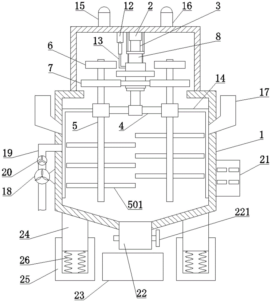
As shown in fig. 1, a schematic structural diagram of a concrete mixing device for building construction according to an embodiment of the present invention includes:
the stirring device comprises a stirring barrel 1, wherein the top of an inner cavity of the stirring barrel is fixedly provided with a power piece 2, and an output shaft of the power piece 2 is coaxially and fixedly connected with a rotating shaft 3;
the rotating rod 4 is arranged in the stirring barrel 1 and is fixedly connected with the bottom end of the rotating shaft 3, and stirring shafts 5 are symmetrically arranged at two ends of the rotating rod;
as shown in fig. 5, a plurality of stirring rods 501 are arranged on the stirring shaft 5, and the stirring rods 501 on the two stirring shafts 5 are arranged in a staggered manner; the top end of the stirring shaft 5 is coaxially and fixedly connected with a first gear 6 and a second gear 7, and the number of teeth of the first gear 6 and the second gear 7 is different; a fixed sleeve 8 is sleeved on the rotating shaft 3, the fixed sleeve 8 is fixedly connected with the top of the inner cavity of the stirring barrel 1, and a sliding sleeve 9 is arranged on the fixed sleeve 8 in a sliding manner; the sliding sleeve 9 is connected with a driving part and is driven by the driving part to slide on the fixed sleeve 8; as shown in fig. 4, a third gear 10 and a fourth gear 11 capable of meshing with the first gear 6 and the second gear 7 are fixedly arranged on the sliding sleeve 9; as shown in fig. 2 and 3, the third gear 10 and the first gear 6 are in a first state when they are engaged with each other, and the fourth gear 11 and the second gear 7 are in a second state when they are engaged with each other, and the first state and the second state do not exist at the same time.
In the embodiment of the present invention, the number of teeth of the first gear 6 is less than the number of teeth of the second gear 7, so that under the condition that the rotation speed of the rotating shaft 3 is not changed, the rotation speed of the stirring shaft 5 in the first state is higher than the rotation speed thereof in the second state; the fixed sleeve 8 is provided with a slide rail 802, and the sliding sleeve 9 is slidably arranged on the slide rail 802; the driving part comprises a hydraulic push rod 12 and a connecting rod 13; the hydraulic push rod 12 is fixedly arranged at the top of the inner cavity of the stirring barrel 1, and the telescopic end of the hydraulic push rod is fixedly connected with the sliding sleeve 9 through the connecting rod 13; in the embodiment of the present invention, the distance between the third gear 10 and the fourth gear 11 is smaller than the distance between the first gear 6 and the second gear 7, so as to ensure that the first state and the second state do not occur simultaneously.
The working principle of the embodiment of the invention is as follows: the power part 2 drives the rotating shaft 3 to rotate, so as to drive the rotating rod 4 to rotate, and further drive the two stirring shafts 5 to rotate around the rotating shaft 3, so that the stirring rods 501 on the two stirring shafts 5 stir the concrete in the stirring barrel 1; the stirring rods 501 on the two stirring shafts 5 are arranged in a staggered manner, so that the stirring rods 501 on the two stirring shafts 5 cannot interfere; when the two stirring shafts 5 rotate around the rotating shaft 3, the first gear 6 and the third gear 10 which are meshed with each other or the second gear 7 and the fourth gear 11 which are meshed with each other drive the stirring shafts 5 to rotate, so that the concrete in the stirring barrel 1 is uniformly stirred, and the concrete stirring effect is improved; the hydraulic push rod 12 and the connecting rod 13 are utilized to drive the sliding sleeve 9 to slide on the fixed sleeve 8, so that the first gear 6 is meshed with the third gear 10, or the second gear 7 is meshed with the fourth gear 11, the device is switched between the first state and the second state, and the rotation speed of the stirring shaft 5 can be adjusted under the condition that the rotation speed of the rotating shaft 3 is unchanged, so that different stirring requirements can be met.
As shown in fig. 1, as another preferred embodiment of the present invention, a first indicator light 15 and a second indicator light 16 for displaying the first state and the second state are arranged on the mixing tank 1; limiting plates 801 are arranged at two ends of the fixed sleeve 8, and the limiting plates 801 can prevent the sliding sleeve 9 from being separated from the fixed sleeve 8; induction switches for controlling the first indicator light 15 and the second indicator light 16 to be turned on are respectively arranged on the limiting plates 801 at the two ends of the fixed sleeve 8; as shown in fig. 2, when the sliding sleeve 9 is located at the top end of the fixed sleeve 8, the device is in the first state, the inductive switch on the limiting plate 801 at the top end of the fixed sleeve 8 is activated under the action of the sliding sleeve 9, the first indicator light 15 is controlled to emit light, and the second indicator light 16 is not illuminated at this time; as shown in fig. 3, when the sliding sleeve 9 is located at the bottom end of the fixed sleeve 8, the device is in the second state, the inductive switch on the limiting plate 801 at the bottom end of the fixed sleeve 8 is activated under the action of the sliding sleeve 9, the second indicator light 16 is controlled to emit light, and the first indicator light 15 is not lit; the first indicator light 15 and the second indicator light 16 can facilitate the staff to judge the state of the device.
As another preferred embodiment of the present invention, two ends of the rotating rod 4 are fixedly connected with scrapers 14, and the scrapers 14 are attached to the inner wall of the stirring barrel 1; dwang 4 pivoted in, dwang 4 drives scraper blade 14 rotates to being attached to concrete on the 1 inner wall of agitator clears up, further improves stirring effect.
As another preferred embodiment of the present invention, the concrete mixing device for building construction further comprises a water pump 18, the water pump 18 is communicated with the inside of the mixing tank 1 through a water pipe 19, the water pump 18 pumps water and adds water into the inside of the mixing tank 1 through the water pipe 19; the water pipe 19 is provided with an adjusting valve 20 for adjusting the water flow; a feed inlet 17 is formed in the side wall of the stirring barrel 1, and concrete raw materials can be added into the stirring barrel 1 from the feed inlet 17; a discharge port 22 is formed in the bottom of the stirring barrel 1, a valve 221 is arranged on the discharge port 22, and a material receiving box 23 with an open top is arranged below the discharge port 22; after the concrete is mixed, the valve 221 is opened, and the mixed concrete falls into the material receiving box 23 from the discharge port 22, so that the mixed concrete is collected.
As another preferred embodiment of the present invention, a console 21 for controlling the operation of the power component 2 and the water pump 18 is arranged on the mixing tank 1; the console 21 can also be used for controlling the operation of the hydraulic push rod 12; through the control platform 21, the operator can conveniently control the device.
As another preferred embodiment of the invention, the bottom of the stirring barrel 1 is fixedly provided with four supporting legs 24, and the four supporting legs 24 are respectively and fixedly arranged at four corners of the bottom of the stirring barrel 1; the supporting legs 24 are arranged in the supporting seats 25 in a sliding mode, and the bottoms of the supporting legs 24 are elastically connected with the supporting seats 25 through springs 26; the device can be damped by utilizing the elasticity of the spring 26, so that the vibration generated in the working process of the device is reduced, and the stability of the device is improved.
In the description of the present invention, it is to be understood that the terms "center", "longitudinal", "lateral", "up", "down", "front", "back", "left", "right", "vertical", "horizontal", "top", "bottom", "inner", "outer", and the like, indicate orientations or positional relationships based on those shown in the drawings, and are used only for convenience in describing the present invention and for simplicity in description, and do not indicate or imply that the referenced devices or elements must have a particular orientation, be constructed and operated in a particular orientation, and thus, are not to be construed as limiting the present invention. Furthermore, the terms "first", "second", etc. are used for descriptive purposes only and are not to be construed as indicating or implying relative importance or implicitly indicating the number of technical features indicated. Thus, a feature defined as "first," "second," etc. may explicitly or implicitly include one or more of that feature. In the description of the present invention, "a plurality" means two or more unless otherwise specified.
In the description of the present invention, it should be noted that, unless otherwise explicitly specified or limited, the terms "mounted," "connected," and "connected" are to be construed broadly, e.g., as meaning either a fixed connection, a removable connection, or an integral connection; can be mechanically or electrically connected; they may be connected directly or indirectly through intervening media, or they may be interconnected between two elements. The specific meaning of the above terms in the present invention can be understood by those of ordinary skill in the art through specific situations.
The above description is only for the purpose of illustrating the preferred embodiments of the present invention and is not to be construed as limiting the invention, and any modifications, equivalents and improvements made within the spirit and principle of the present invention are intended to be included within the scope of the present invention.

Claims (8)

1. The utility model provides a concrete mixing device for construction which characterized in that, concrete mixing device for construction includes:
the top of the inner cavity of the stirring barrel is fixedly provided with a power piece, and an output shaft of the power piece is coaxially and fixedly connected with a rotating shaft;
the rotating rod is arranged in the stirring barrel and is fixedly connected with the bottom end of the rotating shaft, and stirring shafts are symmetrically arranged at two ends of the rotating rod in a rotating manner;
wherein a plurality of stirring rods are arranged on the stirring shaft, and the stirring rods on the two stirring shafts are arranged in a staggered manner; the top end of the stirring shaft is coaxially and fixedly connected with a first gear and a second gear, and the number of teeth of the first gear and the second gear is different; a fixed sleeve is sleeved on the rotating shaft, the fixed sleeve is fixedly connected with the top of the inner cavity of the stirring barrel, and a sliding sleeve is arranged on the fixed sleeve in a sliding manner; the sliding sleeve is connected with the driving part and is driven by the driving part to slide on the fixed sleeve; a third gear and a fourth gear which can be respectively meshed with the first gear and the second gear are fixedly arranged on the sliding sleeve; the third gear and the first gear are in a first state when meshed, the fourth gear and the second gear are in a second state when meshed, and the first state and the second state do not exist at the same time.
2. The concrete mixer for construction according to claim 1, wherein the driving part includes a hydraulic push rod, a connecting rod; the hydraulic push rod is fixedly installed at the top of the inner cavity of the stirring barrel, and the telescopic end of the hydraulic push rod is fixedly connected with the sliding sleeve through the connecting rod.
3. The concrete mixing device for building construction according to claim 2, wherein a first indicator light and a second indicator light are provided on the mixing drum for displaying the first state and the second state, respectively; limiting plates are arranged at two ends of the fixing sleeve, and induction switches used for controlling the first indicator light and the second indicator light to be turned on are respectively arranged on the limiting plates at the two ends of the fixing sleeve.
4. The concrete mixing device for building construction according to claim 1, wherein the two ends of the rotating rod are fixedly connected with scrapers, and the scrapers are attached to the inner wall of the mixing tank.
5. The concrete mixing device for building construction according to claim 1, further comprising a water pump, wherein the water pump is communicated with the interior of the mixing tank through a water pipe, and the water pipe is provided with a regulating valve for regulating the water flow.
6. The concrete mixing device for building construction according to claim 1 or 2, wherein a feed inlet is arranged on the side wall of the mixing barrel, and a discharge outlet is arranged at the bottom of the mixing barrel; the discharge port is provided with a valve, and a material receiving box with an opening at the top is arranged below the discharge port.
7. The concrete mixing device for building construction according to claim 5, wherein a console for controlling the operation of the power member and the water pump is provided on the mixing drum.
8. The concrete mixer for building construction according to claim 1, wherein the bottom of the mixer drum is fixedly provided with support legs, the support legs are slidably arranged in the support seats, and the bottoms of the support legs are elastically connected with the support seats through springs.
CN202110073465.XA 2021-01-20 2021-01-20 Concrete mixing device for construction Pending CN112829065A (en)

Priority Applications (1)

Application Number Priority Date Filing Date Title
CN202110073465.XA CN112829065A (en) 2021-01-20 2021-01-20 Concrete mixing device for construction

Applications Claiming Priority (1)

Application Number Priority Date Filing Date Title
CN202110073465.XA CN112829065A (en) 2021-01-20 2021-01-20 Concrete mixing device for construction

Publications (1)

Publication Number Publication Date
CN112829065A true CN112829065A (en) 2021-05-25

Family

ID=75928806

Family Applications (1)

Application Number Title Priority Date Filing Date
CN202110073465.XA Pending CN112829065A (en) 2021-01-20 2021-01-20 Concrete mixing device for construction

Country Status (1)

Country Link
CN (1) CN112829065A (en)

Cited By (3)

* Cited by examiner, † Cited by third party
Publication number Priority date Publication date Assignee Title
CN114683401A (en) * 2022-03-29 2022-07-01 北京金水源岩土工程有限公司 Comprehensive treatment device for bentonite slurry preparation
CN115042319A (en) * 2022-06-04 2022-09-13 王巍彤 Concrete processing and stirring equipment and method thereof
CN116141520A (en) * 2022-11-30 2023-05-23 江苏绿能家电科技有限公司 Mixed feeding device for household appliance plastic mold

Citations (6)

* Cited by examiner, † Cited by third party
Publication number Priority date Publication date Assignee Title
DE102008060588A1 (en) * 2007-12-07 2009-06-10 Pemat Mischtechnik Gmbh mixer
CN208005972U (en) * 2018-04-03 2018-10-26 李勤 A kind of concrete mixer
CN111775320A (en) * 2020-07-09 2020-10-16 杨玲利 Mixing arrangement and concrete mixing ware
CN211762515U (en) * 2019-10-17 2020-10-27 邵鹏 Bridge building material mixing arrangement
CN211868211U (en) * 2020-03-26 2020-11-06 王明贵 A concrete mixing device for building engineering construction
CN211941466U (en) * 2020-01-18 2020-11-17 刘力 Highway bridge concrete mixing device

Patent Citations (6)

* Cited by examiner, † Cited by third party
Publication number Priority date Publication date Assignee Title
DE102008060588A1 (en) * 2007-12-07 2009-06-10 Pemat Mischtechnik Gmbh mixer
CN208005972U (en) * 2018-04-03 2018-10-26 李勤 A kind of concrete mixer
CN211762515U (en) * 2019-10-17 2020-10-27 邵鹏 Bridge building material mixing arrangement
CN211941466U (en) * 2020-01-18 2020-11-17 刘力 Highway bridge concrete mixing device
CN211868211U (en) * 2020-03-26 2020-11-06 王明贵 A concrete mixing device for building engineering construction
CN111775320A (en) * 2020-07-09 2020-10-16 杨玲利 Mixing arrangement and concrete mixing ware

Non-Patent Citations (2)

* Cited by examiner, † Cited by third party
Title
李东和和丁韧: "《机械设计基础》", 30 September 2015, 国防工业出版社 *
王凯和孙建中: "《工业聚合反应装置》", 30 April 1997, 中国石化出版社 *

Cited By (4)

* Cited by examiner, † Cited by third party
Publication number Priority date Publication date Assignee Title
CN114683401A (en) * 2022-03-29 2022-07-01 北京金水源岩土工程有限公司 Comprehensive treatment device for bentonite slurry preparation
CN115042319A (en) * 2022-06-04 2022-09-13 王巍彤 Concrete processing and stirring equipment and method thereof
CN115042319B (en) * 2022-06-04 2023-10-20 郴州东华混凝土有限公司 Concrete processing stirring equipment and method thereof
CN116141520A (en) * 2022-11-30 2023-05-23 江苏绿能家电科技有限公司 Mixed feeding device for household appliance plastic mold

Similar Documents

Publication Publication Date Title
CN112829065A (en) Concrete mixing device for construction
CN110756075A (en) Food mixer
CN208359079U (en) A kind of blender for concrete mixing plant
CN205364206U (en) High -efficiency concrete mixer
CN207058906U (en) A kind of build concrete quick agitator
CN109435059A (en) A kind of energy-saving double-shaft concrete mixer of variable capacity
CN211440560U (en) Mixing system for concrete processing
CN208005972U (en) A kind of concrete mixer
CN209903594U (en) Cement paste stirring structure
CN208484019U (en) Novel environment friendly premixing mortar production device
CN209190991U (en) A kind of agitating device for building of high-efficiency stirring
CN216578540U (en) Mortar production is with material proportioning device
CN213198232U (en) Water conservancy construction concrete agitator
CN214973682U (en) Cement raw materials mixing stirring device for production
CN205438890U (en) Construction is with mixing earth mixer
CN215241802U (en) Cement compounding filling device of highway construction
CN211362882U (en) Novel concrete ratio device
CN216329169U (en) Cement stirring device
CN220614463U (en) Double-horizontal-shaft dry-mixed mortar mixer
CN221187026U (en) Compounding ware that construction was used
CN213648104U (en) Environment-friendly cement agitated vessel
CN219311611U (en) Vertical circulating concrete mixer applied to concrete production line
CN219902688U (en) A mixed structure for cement mixer
CN220840840U (en) Multistage agitating unit of mortar
CN219338117U (en) Proportioning device for cement concrete production

Legal Events

Date Code Title Description
PB01 Publication
PB01 Publication
SE01 Entry into force of request for substantive examination
RJ01 Rejection of invention patent application after publication

Application publication date: 20210525