CN112817153B - Optical pupil expanding device with large field angle, display device and method - Google Patents
Optical pupil expanding device with large field angle, display device and method Download PDFInfo
- Publication number
- CN112817153B CN112817153B CN202110006780.0A CN202110006780A CN112817153B CN 112817153 B CN112817153 B CN 112817153B CN 202110006780 A CN202110006780 A CN 202110006780A CN 112817153 B CN112817153 B CN 112817153B
- Authority
- CN
- China
- Prior art keywords
- light
- doe
- pupil
- grating
- exit pupil
- Prior art date
- Legal status (The legal status is an assumption and is not a legal conclusion. Google has not performed a legal analysis and makes no representation as to the accuracy of the status listed.)
- Active
Links
- 210000001747 pupil Anatomy 0.000 title claims abstract description 368
- 230000003287 optical effect Effects 0.000 title claims abstract description 53
- 238000000034 method Methods 0.000 title claims abstract description 11
- 239000013598 vector Substances 0.000 claims description 154
- 101100285402 Danio rerio eng1a gene Proteins 0.000 claims description 24
- 230000001902 propagating effect Effects 0.000 claims description 18
- 238000010168 coupling process Methods 0.000 claims description 9
- 238000005859 coupling reaction Methods 0.000 claims description 9
- 230000008878 coupling Effects 0.000 claims description 8
- 101150097504 LHX1 gene Proteins 0.000 claims description 7
- 239000011358 absorbing material Substances 0.000 claims description 4
- AIXMJTYHQHQJLU-UHFFFAOYSA-N chembl210858 Chemical compound O1C(CC(=O)OC)CC(C=2C=CC(O)=CC=2)=N1 AIXMJTYHQHQJLU-UHFFFAOYSA-N 0.000 claims description 4
- 238000002955 isolation Methods 0.000 claims description 4
- 239000010410 layer Substances 0.000 claims description 4
- 230000002911 mydriatic effect Effects 0.000 claims description 3
- 238000005253 cladding Methods 0.000 claims description 2
- 238000000151 deposition Methods 0.000 claims description 2
- 239000011241 protective layer Substances 0.000 claims description 2
- 238000003892 spreading Methods 0.000 claims description 2
- 101000581817 Rattus norvegicus Regenerating islet-derived protein 3-alpha Proteins 0.000 claims 4
- 229910004444 SUB1 Inorganic materials 0.000 description 42
- 102100036464 Activated RNA polymerase II transcriptional coactivator p15 Human genes 0.000 description 40
- 101000713904 Homo sapiens Activated RNA polymerase II transcriptional coactivator p15 Proteins 0.000 description 40
- 101100455666 Saccharomyces cerevisiae (strain ATCC 204508 / S288c) LUC7 gene Proteins 0.000 description 36
- 101100073174 Schizosaccharomyces pombe (strain 972 / ATCC 24843) jhd1 gene Proteins 0.000 description 36
- 101100011382 Aspergillus niger eglB gene Proteins 0.000 description 20
- 101150067694 ENG1 gene Proteins 0.000 description 20
- 101100172292 Saccharomyces cerevisiae (strain ATCC 204508 / S288c) DSE4 gene Proteins 0.000 description 20
- 238000010586 diagram Methods 0.000 description 14
- 101000930354 Homo sapiens Protein dispatched homolog 1 Proteins 0.000 description 12
- 102100035622 Protein dispatched homolog 1 Human genes 0.000 description 12
- 230000005540 biological transmission Effects 0.000 description 10
- 230000000644 propagated effect Effects 0.000 description 6
- 102100037373 DNA-(apurinic or apyrimidinic site) endonuclease Human genes 0.000 description 3
- 101000806846 Homo sapiens DNA-(apurinic or apyrimidinic site) endonuclease Proteins 0.000 description 3
- 101000835083 Homo sapiens Tissue factor pathway inhibitor 2 Proteins 0.000 description 3
- 108700012368 REG3B Proteins 0.000 description 3
- 101150043784 Reg3b gene Proteins 0.000 description 3
- 101100257694 Arabidopsis thaliana SRF2 gene Proteins 0.000 description 2
- 101001042415 Cratylia mollis Mannose/glucose-specific lectin Cramoll Proteins 0.000 description 2
- 102100029775 Eukaryotic translation initiation factor 1 Human genes 0.000 description 2
- 101000746134 Homo sapiens DNA endonuclease RBBP8 Proteins 0.000 description 2
- 101001012787 Homo sapiens Eukaryotic translation initiation factor 1 Proteins 0.000 description 2
- 101000969031 Homo sapiens Nuclear protein 1 Proteins 0.000 description 2
- 101000643378 Homo sapiens Serine racemase Proteins 0.000 description 2
- 101000652366 Homo sapiens Spermatogenesis-associated protein 6 Proteins 0.000 description 2
- 102100021133 Nuclear protein 1 Human genes 0.000 description 2
- 102100030258 Spermatogenesis-associated protein 6 Human genes 0.000 description 2
- 230000003190 augmentative effect Effects 0.000 description 2
- 239000003086 colorant Substances 0.000 description 2
- 238000009826 distribution Methods 0.000 description 2
- 239000004973 liquid crystal related substance Substances 0.000 description 2
- 229920003229 poly(methyl methacrylate) Polymers 0.000 description 2
- 239000004926 polymethyl methacrylate Substances 0.000 description 2
- 101100219315 Arabidopsis thaliana CYP83A1 gene Proteins 0.000 description 1
- 101001020548 Homo sapiens LIM/homeobox protein Lhx1 Proteins 0.000 description 1
- 101000976913 Homo sapiens Lens fiber major intrinsic protein Proteins 0.000 description 1
- 102100036133 LIM/homeobox protein Lhx1 Human genes 0.000 description 1
- 101100269674 Mus musculus Alyref2 gene Proteins 0.000 description 1
- 101100140580 Saccharomyces cerevisiae (strain ATCC 204508 / S288c) REF2 gene Proteins 0.000 description 1
- XUIMIQQOPSSXEZ-UHFFFAOYSA-N Silicon Chemical compound [Si] XUIMIQQOPSSXEZ-UHFFFAOYSA-N 0.000 description 1
- 230000015572 biosynthetic process Effects 0.000 description 1
- 238000004049 embossing Methods 0.000 description 1
- 238000005530 etching Methods 0.000 description 1
- 239000011521 glass Substances 0.000 description 1
- 210000003128 head Anatomy 0.000 description 1
- 238000012986 modification Methods 0.000 description 1
- 230000004048 modification Effects 0.000 description 1
- 238000000465 moulding Methods 0.000 description 1
- 238000005457 optimization Methods 0.000 description 1
- 239000004417 polycarbonate Substances 0.000 description 1
- 229920000515 polycarbonate Polymers 0.000 description 1
- 229910052710 silicon Inorganic materials 0.000 description 1
- 239000010703 silicon Substances 0.000 description 1
- 239000011343 solid material Substances 0.000 description 1
Images


Classifications
-
- G—PHYSICS
- G02—OPTICS
- G02B—OPTICAL ELEMENTS, SYSTEMS OR APPARATUS
- G02B6/00—Light guides; Structural details of arrangements comprising light guides and other optical elements, e.g. couplings
- G02B6/0001—Light guides; Structural details of arrangements comprising light guides and other optical elements, e.g. couplings specially adapted for lighting devices or systems
- G02B6/0011—Light guides; Structural details of arrangements comprising light guides and other optical elements, e.g. couplings specially adapted for lighting devices or systems the light guides being planar or of plate-like form
- G02B6/0075—Arrangements of multiple light guides
-
- G—PHYSICS
- G02—OPTICS
- G02B—OPTICAL ELEMENTS, SYSTEMS OR APPARATUS
- G02B27/00—Optical systems or apparatus not provided for by any of the groups G02B1/00 - G02B26/00, G02B30/00
- G02B27/01—Head-up displays
- G02B27/0101—Head-up displays characterised by optical features
-
- G—PHYSICS
- G02—OPTICS
- G02B—OPTICAL ELEMENTS, SYSTEMS OR APPARATUS
- G02B27/00—Optical systems or apparatus not provided for by any of the groups G02B1/00 - G02B26/00, G02B30/00
- G02B27/0081—Optical systems or apparatus not provided for by any of the groups G02B1/00 - G02B26/00, G02B30/00 with means for altering, e.g. enlarging, the entrance or exit pupil
-
- G—PHYSICS
- G02—OPTICS
- G02B—OPTICAL ELEMENTS, SYSTEMS OR APPARATUS
- G02B27/00—Optical systems or apparatus not provided for by any of the groups G02B1/00 - G02B26/00, G02B30/00
- G02B27/01—Head-up displays
- G02B27/017—Head mounted
- G02B27/0172—Head mounted characterised by optical features
-
- G—PHYSICS
- G02—OPTICS
- G02B—OPTICAL ELEMENTS, SYSTEMS OR APPARATUS
- G02B5/00—Optical elements other than lenses
- G02B5/18—Diffraction gratings
- G02B5/1814—Diffraction gratings structurally combined with one or more further optical elements, e.g. lenses, mirrors, prisms or other diffraction gratings
-
- G—PHYSICS
- G02—OPTICS
- G02B—OPTICAL ELEMENTS, SYSTEMS OR APPARATUS
- G02B6/00—Light guides; Structural details of arrangements comprising light guides and other optical elements, e.g. couplings
- G02B6/0001—Light guides; Structural details of arrangements comprising light guides and other optical elements, e.g. couplings specially adapted for lighting devices or systems
- G02B6/0011—Light guides; Structural details of arrangements comprising light guides and other optical elements, e.g. couplings specially adapted for lighting devices or systems the light guides being planar or of plate-like form
- G02B6/0013—Means for improving the coupling-in of light from the light source into the light guide
- G02B6/0015—Means for improving the coupling-in of light from the light source into the light guide provided on the surface of the light guide or in the bulk of it
- G02B6/0016—Grooves, prisms, gratings, scattering particles or rough surfaces
-
- G—PHYSICS
- G02—OPTICS
- G02B—OPTICAL ELEMENTS, SYSTEMS OR APPARATUS
- G02B6/00—Light guides; Structural details of arrangements comprising light guides and other optical elements, e.g. couplings
- G02B6/0001—Light guides; Structural details of arrangements comprising light guides and other optical elements, e.g. couplings specially adapted for lighting devices or systems
- G02B6/0011—Light guides; Structural details of arrangements comprising light guides and other optical elements, e.g. couplings specially adapted for lighting devices or systems the light guides being planar or of plate-like form
- G02B6/0033—Means for improving the coupling-out of light from the light guide
- G02B6/0035—Means for improving the coupling-out of light from the light guide provided on the surface of the light guide or in the bulk of it
-
- G—PHYSICS
- G02—OPTICS
- G02B—OPTICAL ELEMENTS, SYSTEMS OR APPARATUS
- G02B27/00—Optical systems or apparatus not provided for by any of the groups G02B1/00 - G02B26/00, G02B30/00
- G02B27/01—Head-up displays
- G02B27/0101—Head-up displays characterised by optical features
- G02B2027/0112—Head-up displays characterised by optical features comprising device for genereting colour display
-
- G—PHYSICS
- G02—OPTICS
- G02B—OPTICAL ELEMENTS, SYSTEMS OR APPARATUS
- G02B27/00—Optical systems or apparatus not provided for by any of the groups G02B1/00 - G02B26/00, G02B30/00
- G02B27/01—Head-up displays
- G02B27/0101—Head-up displays characterised by optical features
- G02B2027/0123—Head-up displays characterised by optical features comprising devices increasing the field of view
-
- G—PHYSICS
- G02—OPTICS
- G02B—OPTICAL ELEMENTS, SYSTEMS OR APPARATUS
- G02B27/00—Optical systems or apparatus not provided for by any of the groups G02B1/00 - G02B26/00, G02B30/00
- G02B27/01—Head-up displays
- G02B27/017—Head mounted
- G02B27/0172—Head mounted characterised by optical features
- G02B2027/0174—Head mounted characterised by optical features holographic
-
- G—PHYSICS
- G02—OPTICS
- G02B—OPTICAL ELEMENTS, SYSTEMS OR APPARATUS
- G02B27/00—Optical systems or apparatus not provided for by any of the groups G02B1/00 - G02B26/00, G02B30/00
- G02B27/01—Head-up displays
- G02B27/017—Head mounted
- G02B2027/0178—Eyeglass type
Abstract
The invention discloses an optical pupil expanding device with a large field angle, a display device and a method, comprising a waveguide plate, wherein the waveguide plate comprises: an entrance pupil unit that forms first and second transmitted light by diffracting input light, a first pupil expanding unit that forms third transmitted light by diffracting the first transmitted light, a second pupil expanding unit that forms fourth transmitted light by diffracting the second transmitted light, and an exit pupil unit that forms first output light by diffracting the third transmitted light and second output light by diffracting the fourth transmitted light, the exit pupil unit combining the first output light and the second output light to form combined output light; the entrance pupil unit has a first grating period for forming the first light guiding light and a different second grating period for forming the second light guiding light.
Description
Technical Field
The invention relates to an optical pupil expanding device with a large field angle, a display device and a method, which can be used in a virtual display device.
Background
Referring to fig. 1, the pupil expanding device EPE0 comprises a waveguide plate SUB01, which in turn comprises a diffractive entrance pupil element DOE01, a diffractive pupil expanding element DOE02 and a diffractive exit pupil element DOE03. One input light IN1 is expanded by multiple diffraction IN the pupil expanding device EPE0, and finally outputs light OUT1.
Input light IN1 is emitted by optical engine ENG 1. The optical engine ENG1 may consist of a micro display DISP1 and collimating optics LNS 1.
The diffractive entrance pupil unit DOE01 diffracts the input light IN1 into first transmitted light B1 by diffraction. The first guided light B1 is diffracted by the diffractive pupil expanding unit DOE02 to form expanded second guided light B2. The expanded second guided light B2 is diffracted into output light OUT1 by the diffractive exit pupil element DOE03.
The pupil expanding device EPE0 may expand the light beam in both directions SX and SY. The width of the output light OUT1 is much larger than that of the input light IN1. The pupil expanding device EPE0 may be used to expand the viewing pupil of the virtual display device in order to facilitate a larger comfortable viewing position (large EYE box) of the EYE1 relative to the viewing position of the virtual display device. The EYE1 of the observer can see the completed virtual image within the observation position of the output light beam. The output light may comprise one or more output beams, where each output beam may correspond to a different image location of the displayed virtual image VIMG1. The pupil expansion device may also be referred to as, for example, a pupil expansion unit, a pupil expansion device, or the like.
The virtual image VIMG1 has an angular amplitude LIM1. Fig. 1 shows a manner of displaying a full-color virtual image VIMG1 by using the pupil expanding device EPE0, and the total reflection condition of the waveguide plate SUB01 cannot be satisfied during transmission due to the corner rays of the virtual image VIMG1 corresponding to red and blue. Therefore, the corner of the virtual image VIMG1 appears to lack red or blue.
Disclosure of Invention
The present invention proposes a new pupil expanding device, and at the same time a method of expanding light beams, and at the same time a display device, and a method for displaying an image, which may provide a larger field of view angle (FOV).
According to the configuration, the invention proposes an optical pupil expansion device (EPE 1), the key parts of which are as follows:
waveguide plate (SUB 1), comprising:
-an entrance pupil unit (DOE 1) by which the input light (IN 1) is diffracted to form a first transmitted light (B1 a) and a second transmitted light (B1B);
-a first pupil expanding element (DOE 2 a) forming a third light transmitted (B2 a) by diffracting the first light transmitted (B1 a);
-a second pupil expanding element (DOE 2B) for forming a fourth light guiding light (B2B) by diffracting the second light guiding light (B1B); and
-an exit pupil unit (DOE 3) forming a first output light (OB 3 a) by diffracting the third transmitted light (B2 a) and a second output light (OB 3B) by diffracting the fourth transmitted light (B2B);
wherein the exit pupil unit (DOE 3) combines the first output light (OB 3 a) and the second output light (OB 3 b) to form a combined output light (OUT 1); wherein the entrance pupil element (DOE 1) has a first grating period (d) for forming the first light-transmitting light (B1 a) 1a ) And the entrance pupil element (DOE 1) has a different second grating period (d) for forming the second light-conducting light (B1B) 1b )。
Other embodiments are defined in the claims.
The scope of protection sought for the various embodiments of the invention is defined by the independent claims. The embodiments described in the present invention, if any, which do not belong to the scope of the independent claims are to be interpreted as examples to facilitate the understanding of the various embodiments of the invention.
The pupil expanding device may be used to display a color image, wherein the display width of the color image is increased. The color image may be an RGB image, comprising red (R) light, green (G) light, and blue (B) light.
Increasing the width of the displayed image may result in leakage of blue and/or red light at the corner points of the displayed image. In other words, red or blue light, which is formed by the entrance pupil unit of the pupil expanding device, cannot be confined entirely within the waveguide plate by total internal reflection.
The pupil expansion device can be designed to contain two different light paths in order to overcome the limitation of the waveguide plate for different colors of light in the corresponding propagation directions when transmitting a wide image.
The pupil expanding device may divide the input light to propagate to the exit pupil unit via a first path and via a second path, respectively. The first path may be realized from the entrance pupil unit to the exit pupil unit by the first pupil expanding unit. The second path may be realized from the entrance pupil unit to the exit pupil unit by a second mydriatic unit. By optimizing the first path for propagating blue light at a corner point, while by optimizing the second path for propagating red light at a corner point. Thus, the pupil expanding device can cause the red and blue colors of the displayed image to be displayed normally at all corner points. The corner red light may be conducted through at least one path, and the corner blue light may be conducted through at least one path.
When optimization is required and the angular amplitude of the displayed image increases, the first path may have red light loss at the corner points of the displayed image and the second path may have blue light loss at the corner points of the displayed image. However, the red light propagating along the second path may at least partially compensate for the loss of red light from the first path. The blue light propagating along the first path may at least partially compensate for the loss of blue light from the second path.
The entrance pupil unit may contain a first diffractive feature to diffract light into the first pupil expanding unit. The entrance pupil unit may contain a second diffractive feature to diffract light into the second pupil expanding unit. The first diffractive feature may have a first grating period and the second diffractive feature may have a second, different grating period. The first grating period may be selected to ensure that the blue guided light at the corner points is confined within the waveguide plate. The second grating period may be chosen to ensure that the red guided light at the corner points is confined within the waveguide plate. The first diffractive features may have a first direction and the second diffractive features may have a different second direction.
The two paths together may at least partially compensate for color deviations of corner points of the displayed image. The two paths may reduce or avoid color errors at corner points of a wide color display image. The two paths may improve the color uniformity of a wide color display image.
The exit pupil unit may form the first output light by diffracting the third transmitted light propagating along the first path. The diffracted third transmitted light is from the first pupil expanding unit. The exit pupil unit may form the second output light by diffracting fourth transmitted light that propagates along the second path. The diffracted fourth conducted light is from the second pupil expanding unit. The first output light may spatially overlap with the second output light. By combining the first output light with the second output light, a combined output light is formed at the exit pupil unit.
The exit pupil unit may contain first diffractive features to diffract the transmitted light received from the first pupil expanding unit. The exit pupil unit may contain second diffractive features to diffract the transmitted light received from the second pupil expanding unit. The first diffractive feature may have a first grating period and the second diffractive feature may have a second, different grating period. The first grating period may be selected to ensure that the blue guided light at the corner points is confined within the waveguide plate. The second grating period may be chosen to ensure that the red guided light at the corner points is confined within the waveguide plate. The first diffractive feature may have a first direction and the second diffractive feature may have a different second direction. The first diffractive feature may have a very low or negligible out-coupling pupil efficiency for light received from the second pupil expanding unit. The second diffractive feature may be very low or negligible for the coupled-out pupil efficiency of the light received from the first pupil expanding unit.
Drawings
In order to more clearly illustrate the technical solutions of the embodiments of the present invention, the drawings needed to be used in the description of the embodiments are briefly introduced below, and it is obvious that the drawings in the following description are some embodiments of the present invention, and it is obvious for those skilled in the art to obtain other drawings based on these drawings without creative efforts.
Figure 1 is a schematic diagram of a conventional pupil expansion device 20;
FIGS. 2 a-2 e are three-dimensional views illustrating examples of incident light rays formed using an optical engine;
FIG. 2f is an example of a display process for representing a virtual image in a three-dimensional view;
FIG. 2g is an example of horizontal angular amplitude (angular width) of a virtual image;
FIG. 2h is an example of pitch angle amplitude (angular height) of a virtual image;
figure 3a is an example of a front view of a pupil expanding device providing two different paths for the entrance pupil rays;
figure 3b is an example of a front view of different exit pupil regions of an exit pupil unit in a pupil expanding device;
figure 4a shows an example of a display device comprising a pupil expanding device in a three-dimensional view;
FIG. 4b is a three-dimensional view illustrating an example of a combined output light formed by the superposition of the first output light and the second output light;
figure 4c shows an example of a display device comprising a pupil expanding device in a cross-sectional view;
figure 5 is an elevational view of the pupil expanding device with relevant dimensional and structural details labeled in an embodiment of the present invention;
figure 6a is an example of a vector diagram of the blue light wave vector propagating along the first path of the pupil expanding device in an embodiment of the present invention;
figure 6b is an example of a vector diagram of a red light wave vector propagating along the first path of the pupil expanding device in an embodiment of the present invention,
FIG. 6c is an exemplary vector diagram of the blue light wave vectors of the image corner points in an embodiment of the present invention;
FIG. 6d is an exemplary vector diagram of blue light wave vectors of image corner points according to an embodiment of the present invention;
FIG. 6e is an exemplary vector diagram of the red wave vectors of the image corner points in an embodiment of the present invention;
FIG. 6f is an exemplary vector diagram of the red wave vectors of the image corner points in an embodiment of the present invention;
FIG. 6g is a diagram of a first guided light formed by coupling an input light beam into a waveguide plate, where the first guided light has a tilt angle near the critical angle for total internal reflection, according to an embodiment of the present invention;
fig. 6h illustrates the formation of first guided light by coupling an input beam into a waveguide plate, wherein the first guided light is tilted at an angle close to 90 degrees, according to an embodiment of the present invention;
figure 6i shows the relationship between the wave vector angle of the first transmitted light and the wave vector angle of the input light in an embodiment of the present invention,
figure 7a is an example of a vector diagram of a blue light wave vector propagating along the second path of the pupil expanding device in an embodiment of the present invention;
figure 7b is an example of a vector diagram of the red light wave vectors propagating along the second path of the pupil expanding device in an embodiment of the present invention;
FIG. 7c is an exemplary vector diagram of the blue light wave vectors of the image corner points in an embodiment of the present invention;
FIG. 7d is an exemplary vector diagram of the blue light wave vectors of the corner points of the image in an embodiment of the present invention;
figure 8a is an example of the propagation of light rays at a first corner point of the pupil expanding device in an embodiment of the present invention;
figure 8b is an example of the propagation of light rays at the center point of the pupil expanding device in an embodiment of the present invention;
figure 8c is an example of the light propagation pattern at the third corner of the pupil expanding device in an embodiment of the present invention;
figure 8d is an example of the propagation of light rays at a second corner point of the pupil expanding device in an embodiment of the present invention;
figure 8e is an example of the light propagation pattern at the fourth corner of the pupil expanding device in an embodiment of the invention.
Detailed Description
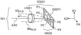
As shown in fig. 2a to 2e, the optical engine ENG1 may be composed of a display DISP1 and collimating optics LNS 1. The display DISP1 may be arranged to display an input image IMG0. The display DISP1 may also be referred to as a microdisplay or microdisplay. The display DISP1 may also be referred to as a spatial intensity modulator. The input image IMG0 may also be referred to as an image source.
The input image IMG0 may include a center point P0 and four corner points P1, P2, P3, P4. P1 may represent the upper left corner drop point. P2 may represent the upper right corner drop point. P3 may represent the lower left corner drop point. P4 may represent the lower right corner drop point. The input image IMG0 may contain graphic characters such as "F", "G", and "H".
The input image IMG0 may be a color image. The input image IMG0 may be, for example, an RGB image, which may contain a red partial image, a green partial image, and a blue partial image. Each image point may provide, for example, red, green and/or blue light. The red beam of light may have a red color, e.g., a wavelength of 650nm, and the green beam of light may have a green color, e.g., a wavelength of 510nm. The light of the blue beam may have a blue color, e.g. a wavelength of 470nm. In particular, the light at the corner points of the color image IMG0 may include red light and blue light.
Optical engine ENG1 may provide input light IN1, which may comprise a plurality of substantially collimated light beams (B0). Each red light beam may propagate in a different direction and may correspond to a different point of the input image IMG0. For example, the red beam B0 P1,R May correspond to the image point P1 and at the wave-vector k0 P1,R Is propagated in the direction of (a).
Furthermore, a blue light beam (B0) P1,B ) May correspond to the sameImage point P1, and at wave vector (k 0) P1,B ) Is propagated in the direction of (a).
The input light IN1 is a blue light beam (B0) corresponding to a first corner point P1 of the input image IMG0 P1,B ) Propagation direction (k 0) P1,B ) The red light beam (B0) corresponding to the first angle point P1 can be parallel P1,R ) Propagation direction (k 0) P1,R )。
The input light IN1 is a blue light beam (B0) corresponding to a second corner point P2 of the input image IMG0 P2,B ) Propagation direction (k 0) P2,B ) May be parallel to the red light beam (B0) corresponding to the second corner point P2 P2,R ) Propagation direction (k 0) P2,R )。
Red light beam B0 P2,R May correspond to the image point P2 and at the wave-vector k0 P2,R Is propagated in the direction of (a). Red light beam B0 P3,R May correspond to the image point P3 and at the wave-vector k0 P3,R Is propagated in the direction of (a). Red light beam B0 P4,R May correspond to the image point P4 and at the wave-vector k0 P4,R Is propagated in the direction of (a). Red light beam B0 P0,R May correspond to the central image point P1 and at the wave-vector k0 P0,R Is propagated in the direction of (a).
The wave vector (k) of light can be defined as a vector having a propagation direction of said light and having an amplitude given by 2 pi/lambda, where lambda is the wavelength of said light.
Referring to fig. 2f, output light OUT1 (i.e., combined output light OUT 1) may comprise a plurality of output beams, which may correspond to displayed virtual image VIMG1. Each output beam may correspond to a point of the image. For example, at wave vector k3 P0,R May correspond to point P0' of virtual image VIMG1. Wave vector k3 P1,R May correspond to point P1' of the virtual image VIMG1. Along wave vector k3 P2,R May correspond to point P2' of virtual image VIMG1. Wave vector k3 P3,R May correspond to point P3' of the virtual image VIMG1. Wave vector k3 P4,R May correspond to point P4' of the virtual image VIMG1.
The pupil expanding device EPE1 may form the output light OUT1 by expanding the exit pupil of the optical engine ENG 1. The output light OUT1 may include a plurality of output light beams corresponding to the displayed virtual image VIMG1. The output light beam OUT1 may be irradiated on the EYE1 of the observer so that the observer can see the displayed virtual image VIMG1.
The displayed virtual image VIMG1 may have a center point P0' and four corner points P1', P2', P3', P4'. The input light IN1 may include a plurality of light beams corresponding to points P0, P1, P2, P3, P4 of the input image IMG0. The pupil expanding device EPE1 may form a point P0' of the displayed virtual image VIMG1 by diffracting and guiding light from the point P0 of the input image IMG0. The pupil expanding device EPE1 may form the points P1', P2', P3', P4' by diffracting and guiding light from the points P1, P2, P3, P4, respectively.
The pupil expanding device EPE1 can form an output light OUT1 which is contained by a wave vector k3 P0,R ,k3 P1,R ,k3 P2,R ,k3 P3,R ,k3 P4,R Etc. in specified different directions.
The red light beam corresponding to point P0' of the displayed virtual image VIMG1 has a wave vector k3 P0,R . The red light beam corresponding to point P1' of the virtual image VIMG1 has a wave vector k3 P1,R . The red light beam corresponding to the point P2' of the virtual image VIMG1 has a wave vector k3 P2,R . The red light beam corresponding to the point P3' of the virtual image VIMG1 has a wave vector k3 P3,R . The red light beam corresponding to the point P4' of the virtual image VIMG1 has a wave vector k3 P4,R 。
The pupil expanding unit EPE1 may be designed such that the wave vector k3 P1,R Wave vector k0 of red light beam with point P1 IN input light IN1 P1,R Parallel. Wave vector k3 P0,R A wave vector k0 which can be associated with a point P0 IN the input light IN1 P0,R Parallel. Wave vector k3 P2,R Can be associated with the wave vector k0 of the point P2 IN the input light IN1 P2,R Parallel. Wave vector k3 P3,R Can be associated with the wave vector k0 of the point P3 IN the input light IN1 P3,R Parallel. Wave vector k3 P4,R A wave vector k0 which can be associated with a point P4 IN the input light IN1 P4,R Parallel.
In fig. 2g and 2h, the virtual image VIMG1 is displayed with an angular width And an angular height Δ θ.
The displayed virtual image VIMG1 may have a first corner point P1', for example, on the left side of the virtual image VIMG1, and a second corner point P2', for example, on the right side of the virtual image VIMG1. The angular width of the virtual image VIMG1 may be equal to the wave vector k3 of the corner points P1', P2 P1,R ,k3 P2,R The horizontal included angle therebetween.
The displayed virtual image VIMG1 may have an upper corner point P1 'and a lower corner point P3'. The angular height Δ θ of the virtual image VIMG1 may be equal to the wave vector k3 of the angular falling points P1', P3 P1,R ,k3 P3,R The vertical included angle therebetween.
The two paths of the pupil expanding device EPE1 may allow displaying a wide color virtual image VIMG1. The two paths of the pupil expanding device EPE1 may allow the display to have an expanded angular width The color virtual image VIMG1.
Passing azimuth And θ to specify the direction of the wave vector. Angle of rotation
 The angle between the wave vector and the reference plane REF1 can be expressed. The reference plane REF1 may be defined as the plane of the directions SZ and SY. The angle θ may represent the angle between the wave vector and the reference plane REF 2. The reference plane REF2 may be defined as the plane of the directions SZ and SX.
Referring to fig. 3a, the pupil expanding device EPE1 may comprise a substantially planar waveguide plate SUB1, which waveguide plate SUB1 in turn comprises an entrance pupil element DOE1, a first pupil expanding element DOE2a, a second pupil expanding element DOE2b and an exit pupil element DOE3. The grating elements used may be on the first surface or on the second surface of the waveguide plate SUB1.
The entrance pupil unit DOE1 may receive the input light IN1, and the exit pupil unit DOE3 may provide the output light OUT1. The input light IN1 may comprise a plurality of light beams propagating IN different directions. The output light OUT1 may include a plurality of expanded light beams formed by the light beam (B0) IN the input light IN1.
Width w of output light OUT1 OUT1 May be larger than the width w of the input light IN1 IN1 . The pupil expanding device EPE1 may expand the input light IN1 IN two dimensions (e.g. IN the horizontal direction SX and IN the vertical direction SY). The expansion process may also be referred to as pupil expansion. The pupil expanding device EPE1 may be referred to as a beam pupil expanding device or an exit pupil expanding device.
The entrance pupil unit DOE1 may form the first and second light transmission lights B1a and B1B by diffracting the input light IN1. The first guided light B1a and the second guided light B1B may propagate within the planar waveguide plate SUB1. The first and second light-guiding light B1a, B1B may be confined within the waveguide plate SUB1 by total internal reflection.
The term "conducting" may denote that light propagates within the planar waveguide-plate SUB1, thereby confining the light beam within the waveguide-plate by Total Internal Reflection (TIR). The term "guide" may mean the same meaning as the term "waveguide".
The entrance pupil unit DOE1 may couple IN light IN1 via two different paths, i.e. via the first and second pupil expanding units DOE2a, DOE2b, to propagate to the exit pupil unit DOE3. The entrance pupil element DOE1 is coupled in by optics, further via the first pupil expanding element DOE2a and finally to the exit pupil element DOE3. It is also possible to enter the pupil unit DOE1 by optical coupling, then via the second pupil expanding unit DOE2b, and finally to the exit pupil unit DOE3. The pupil expanding device EPE1 may provide a first path from the entrance pupil unit DOE1 via the first pupil expanding unit DOE2a to the exit pupil unit DOE3. The pupil expanding device EPE1 may provide a second path from the entrance pupil unit DOE1 via the second pupil expanding unit DOE2b to the exit pupil unit DOE3. The first path may represent an optical path from the entrance pupil unit DOE1 to the exit pupil unit DOE3 and through the first pupil expanding unit DOE2a. The second path may refer to an optical path from the entrance pupil unit DOE1 to the exit pupil unit DOE3 and through the second pupil expanding unit DOE2b.
The first light-transmitting light B1a may propagate from the entrance pupil unit DOE1 to the first pupil expanding unit DOE2a mainly along the first direction DIR1a. The first pupil expanding unit DOE2a may form the third light transmission light B2a by diffracting the first light transmission light B1a. The lateral dimensions of the third light-guiding light B2a may be larger than the corresponding lateral dimensions of the input light IN1. The third guided light B2a may also be referred to as expanded guided light B2a.
The expanded conducted light B2a may propagate from the first pupil expanding element DOE2a to the exit pupil element DOE3. The expanded guided light B2a may be confined within the waveguide plate SUB1 by total internal reflection.
The exit pupil unit DOE3 may form the first output light OB3a by diffracting the expanded transmitted light B2a.
The second guided light B1B may propagate from the entrance pupil unit DOE1 to the second pupil expanding unit DOE2B mainly along the second direction DIR1B. The second pupil expanding unit DOE2B may form the fourth light transmission B2B by diffracting the second light transmission B1B. The lateral dimensions of the fourth light-guiding light B2a may be larger than the corresponding lateral dimensions of the input light IN1. The fourth conducted light B2B may also be referred to as expanded conducted light B2B.
The expanded conducted light B2B may propagate from the second pupil expanding element DOE2B to the exit pupil element DOE3. The expanded guided light B2B may be confined within the waveguide plate SUB1 by total internal reflection. The exit pupil unit DOE3 may form the second output light OB3B by diffracting the expanded conducted light B2B.
The exit pupil unit DOE3 may diffract the third guided light B2a received from the first pupil expanding unit DOE2a, while the exit pupil unit DOE3 may diffract the fourth guided light B2B received from the second pupil expanding unit DOE2B.
The first direction DIR1a may represent an average propagation direction of the first light-guiding light B1a. The first direction DIR1a may also represent the central axis of propagation of the first light guiding light B1a.
The second direction DIR1B may represent an average propagation direction of the second guided light B1B. The second direction DIR1B may also represent the central axis of propagation of the second guided light B1B.
An angle γ between the first direction DIR1a and the second direction DIR1b 1ab Can beIn the range of 60 ° to 120 °.
The expanded conducted light B2a may propagate in a third direction DIR2a, which may be substantially parallel to the second direction DIR1B. The expanded conducted light B2B may propagate in a fourth direction DIR2B, which may be substantially parallel to the first direction DIR1a.
The waveguide plate SUB1 may comprise one or more optical isolation units ISO1 to prevent direct optical coupling between the first and second pupil expanding units DOE2a, DOE2b. The optical isolation unit ISO1 may be realized by depositing a (black) absorbing material on the surface of the waveguide plate, or (and) by adding a (black) absorbing material into the area of the waveguide plate, or (and) by forming one or more openings in the waveguide plate.
SX, SY and SZ are orthogonal directions. The waveguide plate SUB1 may be parallel to the plane defined by SX and SY.
Referring to fig. 3B, the first pupil expanding unit DOE2a may be arranged to assign the third light guiding light B2a to the first exit pupil region REG3a of the exit pupil unit DOE3. The first exit pupil region REG3a may diffract the third guided light B2a out of the waveguide plate SUB1. The second pupil expanding unit DOE2B may be arranged to distribute the fourth light guiding light B2B to the second exit pupil region REG3B of the exit pupil unit DOE3. The second exit pupil region REG3B may diffract the fourth guided light B2B out of the waveguide plate SUB1.
The first exit pupil region REG3a may overlap with the second exit pupil region REG3b. The common overlapping region COM1 of the first and second exit pupil regions REG3a and REG3B may diffract the third and fourth transmitted light B2a and B2B out of the waveguide plate SUB1. The area of the common overlap region COM1 may be more than 50%, preferably more than 70% of the area of one side of the exit pupil element DOE3.
Referring to fig. 4a to 4c, the pupil expanding device EPE1 may form the output light OUT1 by diffracting and guiding the input light IN1 obtained from the optical engine ENG 1. The display device 500 may comprise an optical engine ENG1 and a pupil expanding device EPE1.
The input light IN1 may comprise a plurality of light beams propagating IN different directions. Each beam of input light IN1 may correspond to a different point of input image IMG0. The output light OUT1 may include a plurality of light beams propagating in different directions. Each beam of output light OUT1 may correspond to a different point of displayed virtual image VIMG1. The pupil expanding unit EPE1 may form the output light OUT1 from the input light IN1 such that the direction and intensity of the light beam of the output light OUT1 correspond to the point of the input image IMG0.
The beam of input light IN1 may correspond to a single image point (P0) of the display image. The pupil expanding device EPE1 may form an output light beam from a light beam from the input light IN1 such that the direction (k) of the output light beam 3,P0,R ) Parallel to the direction (k) of the beam of the respective input light IN1 0,P0,R )。
The pupil expanding device EPE1 may propagate the content of the virtual image from the optical engine ENG1 in front of the EYE1 of the user. The pupil expanding device EPE1 may expand the viewing pupil, thereby expanding the eyebox.
The optical engine ENG1 may include a micro display DISP1 to generate the main image IMG0. The micro display DISP1 may comprise a two-dimensional array of light emitting pixels. The display DISP1 may generate, for example, the main image IMG0 with a resolution of 1280 × 720. The display DISP1 may generate, for example, a main image IMG0 with a resolution of 1920 × 1080 (Full HD)). The display DISP1 may generate, for example, the main image IMG0 with a resolution of 3840 × 2160 (4 KUHD). The primary image IMG0 may contain a plurality of image points P0, P1, P2. Optical engine ENG1 may include collimating optics LNS1 to form a different light beam than each image pixel. Optical engine ENG1 may comprise collimating optics LNS1 to form a substantially collimated beam of light from light at image point P0. The light beam corresponding to the image point P0 may be at the wave-vector k0 P0,R Propagating in the specified direction. The beams corresponding to different image points P1 may be directed in the same directionk0 P0,R Different directions k0 P1,R And (5) spreading.
The optical engine ENG1 may provide a plurality of light beams corresponding to the generated main image IMG0. One or more optical beams provided by the optical engine ENG1 may be coupled into the pupil expanding device EPE1 and serve as input light IN1.
Optical engine ENG1 may comprise, for example, one or more Light Emitting Diodes (LEDs). The display DISP1 may comprise one or more microdisplay imagers, such as Liquid Crystal On Silicon (LCOS), liquid Crystal Display (LCD), digital Micromirror Device (DMD).
The exit pupil unit DOE3 may form the first output light OB3a by diffracting the third transmitted light B2a received from the first pupil expanding unit DOE2a. The exit pupil unit DOE3 may form the second output light OB3B by diffracting the fourth transmitted light B2B received by the second pupil expanding unit DOE2B. By combining the first output light OB3a with the second output light OB3b, a combined output light OUT1 may be formed at the exit pupil element DOE3.
The pupil expanding device EPE1 may be arranged such that the direction of light of a given image point (e.g., P0) in the first output light OB3a is parallel to the direction of light of a given image point (P0) in the second output light OB3b. Thus, combining the first output light OB3a with the second output light OB3b may form a combined light beam corresponding to a given image point (P0).
Each unit DOE1, DOE2a, DOE2b, DOE3 may include one or more diffraction gratings having the diffraction function described above.
The diffraction period (d) and the direction (β) of the diffraction grating of the optical elements DOE1, DOE2a, DOE2b, DOE3 may be selected such that the direction of each beam of output light OUT1 may be parallel to the direction of the corresponding beam of input light IN1.
The grating period (d) and direction (β) of the grating vector may satisfy, for a predetermined integer m 1a ,m 2a ,m 3a Vector sum (m) 1a V 1a +m 2a V 2a +m 3a V 3a ) A condition of zero. V 1a The grating vector of the entrance pupil element DOE1 is indicated. V 2a The grating vectors of the first pupil expanding element DOE2a are indicated. V 3a The grating vector of the exit pupil element DOE3 is indicated. The value of these predetermined integers is typically +1 or-1. Integer m 1a The value of (b) may be +1 or-1. Integer m 2a The value of (b) may be +1 or-1. Integer m 3a The value of (b) may be +1 or-1.
The grating period (d) and direction (β) of the grating vector may satisfy, for a predetermined integer m 1b ,m 2b ,m 3b Vector sum (m) 1b V 1b +m 2b V 2b +m 3b V 3b ) A condition of zero. V 1b The grating vector of the entrance pupil element DOE1 is indicated. V 2b The grating vectors of the second pupil expanding element DOE2b are indicated. V 3b The grating vector of the exit pupil element DOE3 is indicated. The values of these predetermined integers are typically +1 or-1. Integer m 1b The value of (b) may be +1 or-1. Integer m 2b The value of (b) may be +1 or-1. Integer m 3b The value of (b) may be +1 or-1.
The waveguide plate may have a thickness t SUB1 . The waveguide plate comprises a planar waveguide core portion. In one embodiment, the waveguide plate SUB1 may optionally comprise, for example, one or more cladding layers, one or more protective layers and/or one or more mechanical support layers. Thickness t SUB1 May refer to the thickness of the planar waveguide core portion of the waveguide plate SUB1.
The pupil expanding device EPE1 can expand the light beam in two directions: in the direction SX and in the direction SY. The width (IN the SX direction) of the output light OUT1 may be greater than the width of the input light IN1, and the height (IN the SY direction) of the output light OUT1 may be greater than the height of the input light IN1.
The pupil expanding device EPE1 may be arranged to expand the viewing pupil of the virtual display device 500, thereby facilitating the positioning of the EYE1 relative to the display device 500. In the case where the output light OUT1 is incident on the EYE1 of the viewer, the viewer can see the displayed virtual image VIMG1. The output light OUT1 may comprise one or more output light beams, wherein each output light beam may correspond to a different image point (P0 ', P1') of the displayed virtual image VIMG1. The optical engine ENG1 may include a micro display DISP1 for displaying the main image IMG0. The optical engine ENG1 and the pupil expanding device EPE1 may be arranged asConverting a primary image IMG0 into a plurality of input beams (e.g., B0) P0,R ,B0 P1,R ,B0 P2,R ,B0 P3,R ,B0 P4,R ,...,B0 P0,B ,B0 P1,B ,B0 P2,B ,B0 P3,B ,B0 P4,B ,..) and forms output light OUT1 by expanding the input beam. For example, symbol B0 P2,R An input light beam may be represented which corresponds to the image point P2 and has a red color (R). For example, symbol B0 P2,B An input light beam may be represented which corresponds to the image point P2 and has a blue color (B). The input light beams may together constitute input light IN1. The input light IN1 may comprise a plurality of input beams (e.g., B0) P0,R ,B0 P1,R ,B0 P2,R ,B0 P3,R ,B0 P4,R ,...B0 P0,B ,B0 P1,B ,B0 P2,B ,B0 P3,B ,B0 P4,B ,...)。
The output light OUT1 may comprise a plurality of output light beams, each of which may form a different image point (P0 ', P1') of the virtual image VIMG1. The primary image IMG0 may be represented, for example, as graphics and/or text. The main image IMG0 may be represented as, for example, a video. The optical engine ENG1 and the pupil expanding device EPE1 may be arranged to display the virtual image VIMG1 such that each image point (P0 ', P1') of the virtual image VIMG1 corresponds to a different image point on the main image IMG0.
The waveguide plate SUB1 may have a first main surface SRF1 and a second main surface SRF2. First major surface SRF1, second major surface SRF2 may be substantially parallel to a plane defined by directions SX and SY.
Referring to fig. 5, each cell DOE1, DOE2a, DOE2b, DOE3 may include one or more diffraction gratings to diffract light as described above. For example, the cell DOE1 may contain one or more gratings G1a, G1b. For example, the cell DOE2a may contain a grating G2a. For example, the element DOE2b may contain a grating G2b. For example, the cell DOE3 may contain one or more gratings G3a, G3b.
The grating period (d) of the diffraction grating and the direction (β) of the diffraction features of the diffraction grating may be determined by the grating vector V of the diffraction grating. The diffraction grating contains a plurality of diffraction features (F) that can be used as diffraction lines. The diffractive features may be, for example, tiny ridges or grooves. The diffractive features may also be, for example, microscopic protrusions (or depressions), wherein adjacent protrusions (or depressions) may act as diffraction lines. The grating vector V may be defined as a vector having a direction perpendicular to the diffraction lines of the diffraction grating and an amplitude given by 2 pi/d, where d is the grating period.
The entrance pupil element DOE1 may have a grating vector V 1a ,V 1b . The first pupil expanding element DOE2a may have a grating vector V 2a . The second pupil expanding element DOE2b may have a grating vector V 2b . The exit pupil element DOE3 may have a grating vector V 3a ,V 3b 。
Raster vector V 1a Having a direction beta 1a And a size of 2 pi/d 1a . Raster vector V 1b Having a direction beta 1b And size 2 π/d 1b . Raster vector V 2a Having a direction beta 2a And amplitude 2 pi/d 2a . Raster vector V 2b Having a direction beta 2b And a size of 2 pi/d 2b . Raster vector V 3a Having a direction beta 3a Sum amplitude of 2 pi/d 3b . Raster vector V 3b Having a direction beta 3b Sum amplitude of 2 pi/d 3b . The direction (β) of the grating vector may be defined as the angle between the grating vector and a reference direction (e.g. direction SX).
The grating period (d) and the direction (β) of the diffraction grating of the optical elements DOE1, DOE2a, DOE3 may be chosen such that the propagation direction (k 3) of the light of the central point P0 in the first output light OB3a is such that it is the direction of propagation (k 3) P0,R ) The propagation direction (k 0) of light parallel to the center point P0 IN the input light IN1 P0,R )。
The grating period (d) and the direction (β) of the diffraction grating of the optical elements DOE1, DOE2b, DOE3 may be chosen such that the propagation direction (k 3) of the light of the central point P0 of the second output light OB3b is P0,R ) The propagation direction (k 0) of light from the center point P0 IN the input light IN1 P0,R ) Parallel.
The diffraction periods (d) and the directions (β) of the diffraction gratings of the optical elements DOE1, DOE2a, DOE2b, DOE3 may be chosen such that the propagation direction of the light at the central point P0 of the combined output light OUT1 is in the direction of propagation of the light(k3 P0,R ) The propagation direction (k 0) of light from the center point P0 IN the input light IN1 P0,R ) And are parallel.
Grating vector V of entrance pupil unit DOE1 1a ,V 1b May be, for example, in the range of 60 deg. to 120 deg..
First grating period d of the entrance pupil element DOE1 1a The second grating period d, which may be different from that of the entrance pupil element DOE1 1b To optimize the first path for a first color and the second path for a second, different color.
First grating period d of the exit pupil element DOE3 3a The second grating period d, which may be different from that of the exit pupil element DOE3 3b To optimize the first path for a first color and the second path for a second, different color.
First grating period d of the entrance pupil element DOE1 1a The second grating period d, which may be different from that of the entrance pupil element DOE1 1b For example, a first path for optimizing blue, and a second path for red.
First grating period d of the exit pupil element DOE3 3a The second grating period d, which may be different from that of the exit pupil element DOE3 3b For example, a first path for optimizing blue, and a second path for red.
The grating period (d) and direction (β) of the grating vector may satisfy, for a predetermined integer m 1a ,m 2a ,m 3a Vector sum (m) 1a V 1a +m 2a V 2a +m 3a V 3a ) A condition of zero. V 1a The grating vector of the element DOE1 is represented. V 2a The grating vector of the element DOE2a is represented. V 3a The grating vector of the element DOE3 is represented. The values of these predetermined integers are typically +1 or-1. Integer m 1a The value of (b) may be +1 or-1. Integer m 2a The value of (b) may be +1 or-1. Integer m 3a The value of (b) may be +1 or-1.
The grating period (d) and direction (β) of the grating vector may satisfy, for a predetermined integer m 1b ,m 2b ,m 3b Vector sum (m) 1b V 1b +m 2b V 2b +m 3b V 3b ) A condition of zero. V1b denotes the grating vector of the element DOE 1. V 2b The grating vector of the element DOE2b is represented. V 3b The grating vector of the element DOE3 is represented. The values of these predetermined integers are typically +1 or-1. The integer m1b can have a value of +1 or-1. Integer m 2b The value of (b) may be +1 or-1. Integer m 3b The value of (b) may be +1 or-1.
The entrance pupil element DOE1 may have a first grating vector V 1a To form a first light-conducting light B1a along direction DIR1a and a second grating vector V 1b To form a second light-guiding light B1B along direction DIR1B. The entrance pupil unit DOE1 may have a first diffraction characteristic F1a to provide a first grating having a grating period d 1a And direction beta 1a (relative to the reference direction SX). The entrance pupil unit DOE1 may have a second diffractive feature F1b to provide a second grating having a grating period d 1b And direction beta 1b (relative to the reference direction SX). The entrance pupil element DOE1 may be realized by e.g. a crossed grating or two linear gratings. The entrance pupil unit DOE1 may be, for example, such that a first region of the entrance pupil unit DOE1 contains the diffractive feature F1a, while a second region of the entrance pupil unit DOE1 contains the diffractive feature F1b.
A first linear grating having diffractive features F1a may be arranged on a first main surface of the waveguide plate SUB1 (e.g. on the input-side surface SRF 1) and a second linear grating having diffractive features F1b may be arranged on a second main surface of the waveguide plate SUB1 (e.g. on the output-side surface SRF 2). The diffractive features may be, for example, tiny ridges or tiny protrusions.
The first pupil expanding unit DOE2a may have a grating vector V2a, and the third light transmission B2a is formed by diffracting the first light transmission B1a. The first pupil expanding element DOE2a may have a diffractive feature F2a to provide a grating G2a, the grating G2a having a grating period d 2a And direction beta 2a (relative to the reference direction SX).
The second pupil expanding element DOE2B may have a grating vector V2B, and forms the fourth light transmission B2B by diffracting the second light transmission B1B. The second pupil expanding element DOE2b may haveDiffracting the feature F2b to provide a grating G2b, the grating G2b having a grating period d 2b And direction beta 2b (relative to the reference direction SX).
The exit pupil unit DOE3 may have a first grating vector V3a to couple the expanded third guided light B2a out of the waveguide plate SUB1. The exit pupil element DOE3 may have a second grating vector V3B to couple the expanded fourth guided light B2B out of the waveguide plate SUB1. The exit pupil unit DOE3 may have a diffractive feature F3a to provide a grating G3a with a grating period d3a and a direction β 3a (with respect to the reference direction SX). The exit pupil unit DOE3 may have a diffractive feature F3b to provide a grating G3b with a grating period d3b and a direction β 3b (with respect to the reference direction SX). The exit pupil element DOE3 may be realized by a crossed grating or two linear gratings. A first linear grating G3a with diffractive features F3a may be implemented on a first main surface (e.g. SRF 1) of the waveguide plate SUB1 and a second linear grating G3b with diffractive features F3b may be implemented on a second main surface (e.g. SRF 2) of the waveguide plate SUB1.
The entrance pupil element DOE1 may have a width w 1 And height h 1 . The first pupil expanding cell DOE2a may have a width w 2a And height h 2a . The second pupil expanding element DOE2b may have a width w 2b And height h 2b . The exit pupil element DOE3 may have a width w 3 And height h 3 。
The width may represent a dimension in the direction SX and the height may represent a dimension in the direction SY. The exit pupil element DOE3 may be, for example, substantially rectangular. The edges of the exit pupil unit DOE3 may, for example, be along the directions SX and SY.
Width w of the pupil expanding element DOE2a 2a May be substantially larger than the width w of the entrance pupil element DOE1 1 . The width of the expanded third guided light B2a may be substantially larger than the width w of the entrance pupil unit DOE1 1 。
The waveguide plate SUB1 may comprise or consist essentially of a transparent solid material. The waveguide plate SUB1 may comprise, for example, glass, polycarbonate or Polymethylmethacrylate (PMMA). The diffractive optical elements DOE1, DOE2a, DOE2b, DOE3 can be formed by, for example, molding, embossing and/or etching. The elements DOE1, DOE2a, DOE2b, DOE3 may be realized by, for example, one or more surface diffraction gratings or by one or more volume diffraction gratings.
The spatial distribution of the diffraction efficiency can be arbitrarily adjusted, for example by selecting the local height of the microscopic diffractive features F. Therefore, the height of the microscopic diffractive features F of the exit pupil element DOE3 may be selected to further homogenize the intensity distribution of the output light OUT1.
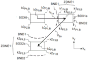
Fig. 6a shows, by way of example, a wave vector of blue light propagating along a first path in the waveguide plate SUB1. The first path may be, for example, clockwise. The wave vector of the input light IN1 may be defined by an initial wave vector k x And k y The region BOX0 of the defined wave vector space. Each angle of the region BOX0 may represent a wave vector of light at a corner point of the input image IMG0 (fig. 7 a).
The wave vector of the first light-transmitting light B1a may be within the region BOX 1a.
The wave vector of the third guided light B2a may be within the region BOX 2a.
The wavevector of the first output light OB3a may be within the region BOX 3.
The entrance pupil unit DOE1 may form the first light-transmitting light B1a by diffracting the input light IN1. By passing the grating vector m of the entrance pupil element DOE1 1a V 1a And the wave vector of the input light IN1 is added to represent diffraction. By applying a raster vector m 1a V 1a The wavevector of the first light guiding B1a is determined by adding to the wavevector of the input light IN1. The wavevector of the third guided light B2a can be determined by combining the grating vector m 2a V 2a Is determined in addition to the wave vector of the first light-guiding light B1a. By applying a raster vector m 3a V 3a The wavevector added to the second light guide B2a determines the wavevector of the first output light OB3a.
BND1 denotes a first boundary for satisfying the Total Internal Reflection (TIR) criterion in the waveguide plate SUB1. BND2 denotes the second boundary of the largest wave vector in the waveguide plate SUB1. The maximum wave vector may be determined by the refractive index of the waveguide plate. Light can be waveguided in the waveguide plate SUB1 only when the wave vector of said light is in the region ZONE1 between the first boundary BND1 and the second boundary BND 2. If the wave vector of the light is outside the ZONE1, the light may leak out of the waveguide plate or not propagate at all.
The grating period d of the entrance pupil element DOE1 can be chosen 1a So that, for example, all wavevectors of the first light conducting B1a of blue color are within the region ZONE1 defined by the boundaries BND1, BND 2.
Fig. 6b shows by way of example the wave vector of red light propagating along a first path within the waveguide plate SUB1.
Now, if the grating period d of the entrance pupil element DOE1 has been selected 1a So that all wavevectors of the first blue light-transmitting guide B1a are within the ZONE1, the wavevectors of the red light of some corner points may be located outside the ZONE 1. In other words, the waveguide plate SUB1 cannot confine or conduct red light at certain corner points of the input image IMG0.
The wave vector falling within the subregion FAIL1 of the region BOX1a corresponds to a case where the input unit DOE1 cannot form the light-guiding light by diffracting the input light. In other words, the diffraction equation does not have a correct practical solution for the wave vectors present in the sub-region FAIL1 of the region BOX 1a. Thus, in case the wavevector of the guided light is outside the ZONE1, it is not possible to couple red light into the waveguide plate for some image points.
In case the wavevector of the guided light is outside the ZONE1, the leakage of red light may limit the angular width of the displayed virtual image VIMG1 for some (other) image points.
Thus, the boundaries BND1, BND2 of the ZONE1 may limit the angular width of the displayed virtual image VIMG1 Forming a wave vector outside the ZONE1 may mean light leakage from the waveguide plate or light coupling failure.
k x Denotes the direction in wave-vector space, where the direction k x Parallel to the direction SX of the physical space. k is a radical of y Denotes the direction in wave vector space, where k y The direction is parallel to the SY direction of the real space. Symbol k z (not shown in the figure) showDirections in wave vector space, where the direction k z Parallel to the direction SZ of the real space. Wave vector k may have a direction k x ,k y And/or k z The component (c) above.
Fig. 6c and 6d show, by way of example, the wave vectors of the blue light at the image points (P0, P1, P2, P3, P4) in the wave vector space.
Fig. 6e and 6f show, by way of example, the wave vectors of the red light at the image points (P0, P1, P2, P3, P4) in the wave vector space.
FIG. 6g shows, in a cross-sectional side view, coupling of input light into a waveguide plate to form first guided light, wherein the first guided light has an inclination angle Near the critical angle for total internal reflection of SUB1
 The situation of fig. 6g corresponds to the operation in the vicinity of the first boundary BND1 of the
 ZONE 1.
FIG. 6h shows, in a cross-sectional side view, coupling of input light into a waveguide plate to form first guided light, wherein the first guided light has an inclination angle Approximately 90 degrees. The situation of fig. 6h may correspond to an operation near the second boundary BND2 of
 ZONE 1.
The curve CRV1 in FIG. 6i gives the tilt angle φ of the wave-vector k1 of the first light-conducting light B1a k1 Input angle phi with wave vector k0 of input light B0 k0 Functional relationship between them. Angle of inclination phi k1 It may be indicated the angle between the wave vector and the direction SZ and a reference plane REF1 defined by SY. By using diffraction equations, the angle can be input The tilt angle is calculated from the grating period of the entrance pupil element DOE1 and the refractive index of the waveguide plate SUB1
 First angle limit phi BND1 May correspond to the tilt angle phi of the first light-conducting k1 Equal to the critical angle for total internal reflection
 The case (1). Second angle limit phi BND2 May correspond to the tilt angle phi of the first light-conducting light k1 Equal to 90 degrees.
Fig. 7a shows by way of example a wave vector diagram of blue light propagating along a second path within the waveguide plate SUB1. The second path may be, for example, a counterclockwise path.
Fig. 7b shows by way of example a wave vector diagram of red light propagating along a second path within the waveguide plate SUB1.
Fig. 7c and 7d show by way of example the wave vectors of the blue light of the image points (P0, P1, P2, P3, P4) in the wave vector space.
The grating period d of the coupling-in pupil element DOE1 can be chosen 1b So that, for example, all wavevectors of the second light guiding light B1B for red are within the region ZONE1 defined by the boundaries BND1, BND 2.
Now, if the grating period d of the entrance pupil element DOE1 has been selected 1b So that all wavevectors of the second light-guiding B1B for red are within the ZONE1, the wavevectors of the blue light for some corner points may be outside the ZONE 1. In other words, the waveguide plate SUB1 cannot confine blue light at certain corner points of the input image IMG0. The leakage of blue light may limit the angular width of the displayed virtual image VIMG1. The wave-vector falling in the sub-region LEAK1 of the region BOX2b represents light that is not confined within the waveguide plate by total internal reflection.
However, the pupil expanding device EPE1 may be arranged to provide a first path and a second path. The first path may provide a full width of the blue virtual image VIMG1 The second path may provide the full width of the red virtual image VIMG1
 Thus, the pupil expanding device EPE1 may be arranged to display images having a full width
 The color virtual image VIMG1.
Thus, the pupil expanding device EPE1 may be arranged to display all corner points (P1, P2, P3, P4) of the color virtual image VIMG1 in red and blue, wherein the color virtual image VIMG1 has the full width of the complete color
Therefore, the angular width of the color virtual image VIMG1 displayed by using the two paths May be substantially larger than the maximum angular width (
LIM 1, predetermined limit) of other pupil expanding devices (EPE 0) that do not use the second path.
The pupil expanding device EPE1 with two paths may be arranged to display a color virtual image VIMG1 with an expanded angular width The first path may be set to limit the blue component of the input image while allowing leakage of red light at one or more corner points of the input image. The second path may be set to limit the red component of the input image while allowing blue light at one or more corner points of the input image to leak out.
For example, when the input light (IN 1) corresponds to the input image (IMG 0) and the width of the input image (IMG 0) Above a predetermined limit (LIM 1), the entrance pupil unit (DOE 1) may be arranged to provide:
-red light (B1 a) corresponding to a first corner point (P1) of the input image (IMG 0) P1,R ),
Wherein the grating vectors (m) of the individual elements (DOE 1, DOE2a, DOE2b, DOE 3) are selected 1a V 1a ,m 2a V 2a ,m 3a V 3a ,m 1b V 1b ,m 2b V 2b ,m 3b V 3b ) So that:
red light of the first corner point (P1) is directed from the entrance pupil element (DOE 1) to the exit pupil element (DOE 3) by the second pupil expanding element (DOE 2 b),
-red light of the first corner point (P1) is not directed from the entrance pupil element (DOE 1) to the exit pupil element (DOE 3) by the first pupil expanding element (DOE 2 a).
For example, when the input light (IN 1) corresponds to the input image (IMG 0) and the width of the input image (IMG 0) Above a predetermined limit (LIM 1), the entrance pupil unit (DOE 1) may be arranged to provide:
-blue light (B1B) corresponding to a second corner point (P2) of the input image (IMG 0) P2,B ),
Wherein the grating vectors (m) of the elements (DOE 1, DOE2a, DOE2b, DOE 3) are selected 1a V 1a ,m 2a V 2a ,m 3a V 3a ,m1bV 1b ,m 2b V 2b ,m 3b V 3b ) So that:
-blue light of the second corner point (P2) is directed from the entrance pupil element (DOE 1) to the exit pupil element (DOE 3) by the first pupil expanding element (DOE 2 a), and
-the blue light of the second corner point (P2) is not directed from the entrance pupil element (DOE 1) to the exit pupil element (DOE 3) by the second pupil expanding element (DOE 2 b).
For example, when the input light (IN 1) corresponds to the input image (IMG 0) and the width of the input image (IMG 0) Above a predetermined limit (LIM 1), the entrance pupil unit (DOE 1) may be arranged to provide:
-red light (B1 a) corresponding to a first corner point (P1) of the input image (IMG 0) P1,R ),
-blue light (B1B) corresponding to a second corner point (P2) of the input image (IMG 0) P2,B ),
Wherein the grating vectors (m) of the individual cells (DOE 1, DOE2a, DOE2b, DOE 3) are selected 1a V 1a ,m 2a V 2a ,m 3a V 3a ,m 1b V 1b ,m 2b V 2b ,m 3b V 3b ) So as to:
red light of the first corner point (P1) is directed from the entrance pupil element (DOE 1) to the exit pupil element (DOE 3) by the second pupil expanding element (DOE 2 b),
red light of the first corner point (P1) is not directed from the entrance pupil element (DOE 1) to the exit pupil element (DOE 3) by the first pupil expanding element (DOE 2 a),
-blue light of the second corner point (P2) is directed from the entrance pupil element (DOE 1) to the exit pupil element (DOE 3) by the first pupil expanding element (DOE 2 a), and
-the blue light of the second corner point (P2) is not directed from the entrance pupil element (DOE 1) to the exit pupil element (DOE 3) by the second pupil expanding element (DOE 2 b).
For example, when the input light (IN 1) corresponds to the input image (IMG 0) and the width of the input image (IMG 0) Above a predetermined limit (LIM 1), the entrance pupil unit (DOE 1) may be arranged to provide:
-red light (B1 a) corresponding to a first corner point (P1) of the input image (IMG 0) P1,R ),
-blue light (B1 a) corresponding to a first corner point (P1) of the input image (IMG 0) P1,B ),
-red light (B1B) corresponding to a second corner point (P2) of the input image (IMG 0) P2,R ),
-blue light (B1B) corresponding to a second corner point (P2) of the input image (IMG 0) P2,B ),
Wherein the grating vectors (m) of the individual elements (DOE 1, DOE2a, DOE2b, DOE 3) are selected 1a V 1a ,m 2a V 2a ,m 3a V 3a ,m 1b V 1b ,m 2b V 2b ,m 3b V 3b ) So that:
red light of the first corner point (P1) is directed from the entrance pupil element (DOE 1) to the exit pupil element (DOE 3) by the second pupil expanding element (DOE 2 b),
red light of the first corner point (P1) is not directed from the entrance pupil element (DOE 1) to the exit pupil element (DOE 3) by the first pupil expanding element (DOE 2 a),
-blue light of the first corner point (P1) is directed from the entrance pupil element (DOE 1) to the exit pupil element (DOE 3) by the first pupil expanding element (DOE 2 a),
the blue light of the first corner point (P1) is directed from the entrance pupil element (DOE 1) to the exit pupil element (DOE 3) by the second pupil expanding element (DOE 2 a),
red light of the second corner point (P2) is directed from the entrance pupil element (DOE 1) to the exit pupil element (DOE 3) by the first pupil expanding element (DOE 2 a),
red light of the second corner point (P2) is directed from the entrance pupil element (DOE 1) to the exit pupil element (DOE 3) by the second pupil expanding element (DOE 2 b),
-blue light of the second corner point (P2) is directed from the entrance pupil element (DOE 1) to the exit pupil element (DOE 3) by the first pupil expanding element (DOE 2 a), and
-the blue light of the second corner point (P2) is not directed from the entrance pupil element (DOE 1) to the exit pupil element (DOE 3) by the second mydriatic element (DOE 2 b).
The pupil expanding device EPE1 may be arranged to operate such that the wave vector of the blue conducting light falls within the region ZONE1 in case the blue conducting light propagates via the first path of the pupil expanding device EPE1, and the pupil expanding device EPE1 may be arranged such that the wave vector of the red conducting light falls within the region ZONE1 in case the red conducting light propagates via the second path of the pupil expanding device EPE1.
Fig. 8a shows, by way of example, the propagation of light at the corner point P1 in the waveguide plate SUB1.
Fig. 8b shows, by way of example, the propagation of light of the center point P0 in the waveguide plate SUB1.
Fig. 8c shows, by way of example, the propagation of the light at the corner point P3 in the waveguide plate SUB1.
Fig. 8d shows, by way of example, the propagation of the light at the corner point P2 in the waveguide plate SUB1.
Fig. 8e shows, by way of example, the propagation of light at the corner point P4 in the waveguide plate SUB1.
The display apparatus 500 may be a virtual reality device 500. The display apparatus 500 may be an augmented reality device 500. The display apparatus 500 may be a near-eye device. The display apparatus 500 may be a wearable device, for example, an earphone. The display device 500 may comprise, for example, a headband through which the display device 500 may be worn on the user's head. During operation of the display device 500, the exit pupil unit DOE3 may be positioned in front of the left EYE1 or the right EYE1 of the user. The display apparatus 500 may project the output light OUT1 into the EYE1 of the user. In one embodiment, the display device 500 may include two optical engines ENG1 and/or two pupil expanding devices EPE1 to display a stereoscopic image. In the augmented reality device 500, the viewer may see real objects and/or environments through the pupil expanding device EPE1 in addition to the displayed virtual image. The optical engine ENG1 may be arranged to generate still images and/or video. Optical engine ENG1 may generate a real main image IMG0 from the digital image. The optical engine ENG1 may receive one or more digital images from an internet server or a smartphone. The display device 500 may be a smart phone. The displayed image may be viewed by a person, and may also be viewed by an animal or machine (possibly including, for example, a camera).
The term "k-vector" may be the same as the term "wave vector".
It is clear that modifications and variations of the device and the method according to the invention are conceivable to those skilled in the art. The figures are schematic. The particular embodiments described above with reference to the drawings are illustrative only and not meant to limit the scope of the invention, which is defined by the appended claims.
Claims (7)
1. An optical pupil expanding device (EPE 1) comprising a waveguide plate (SUB 1) which in turn comprises:
an entrance pupil unit (DOE 1) forming a first light guiding light (B1 a) and a second light guiding light (B1B) by diffracting input light (IN 1),
a first pupil expanding element (DOE 2 a) forming a third light guiding light (B2 a) by diffracting the first light guiding light (B1 a),
-a second pupil expanding element (DOE 2B) forming a fourth light guiding light (B2B) by diffracting the second light guiding light (B1B), and
an exit pupil unit (DOE 3) for forming a first output light (OB 3 a) by diffracting the third light (B2 a) and a second output light (OB 3B) by diffracting the fourth light (B2B),
wherein the exit pupil unit (DOE 3) is arranged to form a combined output light (OUT 1) by combining the first output light (OB 3 a) with the second output light (OB 3 b),
wherein the entrance pupil element (DOE 1) has a first grating period (d) for forming the first light-transmitting light (B1 a) 1a ) And the entrance pupil element (DOE 1) has a different second grating period (d) for forming the second light-conducting light (B1B) 1b );
The first pupil expanding element (DOE 2 a) has a third grating period (d) for forming the third light guiding light (B2 a) 2a ) Said second pupil expanding element (DOE 2B) having a fourth grating period (d) for forming a fourth light (B2B) 2b ) Wherein the third grating period (d) 2a ) Different from the fourth grating period (d) 2b );
The input light (IN 1) corresponds to an input image (IMG 0), and a width of the input image (IMG 0) Above a predetermined limit (LIM 1), the entrance pupil unit (DOE 1) is arranged to provide:
-red light (B1 a) corresponding to a first corner point (P1) of the input image (IMG 0) P1,R ),
Wherein the grating vectors (m) of the respective units (DOE 1, DOE2a, DOE2b, DOE 3) are selected 1a V 1a ,m 2a V 2a ,m 3a V 3a ,m 1b V 1b ,m 2b V 2b ,m 3b V 3b ) So as to:
red light of the first corner point (P1) is directed from the entrance pupil element (DOE 1) to the exit pupil element (DOE 3) by the second pupil expanding element (DOE 2 b),
-red light of the first corner point (P1) is not directed from the entrance pupil element (DOE 1) to the exit pupil element (DOE 3) by the first pupil expanding element (DOE 2 a);
alternatively, the input light (IN 1) corresponds to an input image (IMG 0), and the width of the input image (IMG 0) Above a predetermined limit (LIM 1), the entrance pupil unit (DOE 1) is arranged to provide:
-red light (B1 a) corresponding to a first corner point (P1) of the input image (IMG 0) P1,R ),
-blue light (B1B) corresponding to a second corner point (P2) of the input image (IMG 0) P2,B ),
Wherein the grating vectors (m) of the respective units (DOE 1, DOE2a, DOE2b, DOE 3) are selected 1a V 1a ,m 2a V 2a ,m 3a V 3a ,m 1b V 1b ,m 2b V 2b ,m 3b V 3b ) So as to:
red light of the first corner point (P1) is directed from the entrance pupil element (DOE 1) to the exit pupil element (DOE 3) by the second pupil expanding element (DOE 2 b),
red light of the first corner point (P1) is not directed from the entrance pupil element (DOE 1) to the exit pupil element (DOE 3) by the first pupil expanding element (DOE 2 a),
-blue light of the second corner point (P2) is directed from the entrance pupil element (DOE 1) to the exit pupil element (DOE 3) by the first pupil expanding element (DOE 2 a), and
-the blue light of the second corner point (P2) is not directed from the entrance pupil element (DOE 1) to the exit pupil element (DOE 3) by the second mydriatic element (DOE 2 b);
grating vector (V) of entrance pupil element (DOE 1) 1a ,V 1b ) Is 60 to 120 degrees;
a first grating period (d) of the exit pupil element (DOE 3) 3a ) A second grating period (d) different from the exit pupil element (DOE 3) 3b ) To optimize the first path for a first color and the second path for a second, different color;
the grating period (d) and direction (beta) of the grating vector satisfy the vector sum m 1a V 1a + m 2a V 2a + m 3a V 3a A condition of zero, wherein m 1a ,m 2a ,m 3a Is a predetermined integer, V 1a Grating vector, V, representing the entrance pupil element (DOE 1) 2a A grating vector, V, representing a first pupil expanding element (DOE 2 a) 3a A grating vector representing an exit pupil element (DOE 3);
the waveguide plate (SUB 1) comprises one or more optical isolation units (ISO 1) to prevent direct optical coupling between the first pupil expanding element (DOE 2 a) and the second pupil expanding element (DOE 2 b), the optical isolation units (ISO 1) being realized by depositing an absorbing material on a surface of the waveguide plate, and/or by adding an absorbing material in the region of the waveguide plate, and/or by forming one or more openings in the waveguide plate;
the first pupil expanding element (DOE 2 a) is arranged to distribute the third light (B2 a) to a first exit pupil region (REG 3 a) of the exit pupil element (DOE 3), which first exit pupil region (REG 3 a) diffracts the third light (B2 a) out of the waveguide plate (SUB 1); the second pupil expanding unit (DOE 2B) is arranged to assign the fourth light (B2B) to a second exit pupil region (REG 3B) of the exit pupil unit (DOE 3), the second exit pupil region (REG 3B) diffracting the fourth light (B2B) out of the waveguide plate (SUB 1);
the first exit pupil region (REG 3 a) overlaps the second exit pupil region (REG 3B), a common overlap region (COM 1) of the first exit pupil region (REG 3 a) and the second exit pupil region (REG 3B) diffracts the third guided light (B2 a) and the fourth guided light (B2B) out of the waveguide plate (SUB 1), the area of the common overlap region (COM 1) is greater than 50% of the area of one side of the exit pupil element (DOE 3);
the waveguide plate (SUB 1) has a thickness tSUB1, the waveguide plate comprising a planar waveguide core portion, the waveguide plate (SUB 1) comprising one or more cladding layers, one or more protective layers and/or one or more mechanical support layers, the thickness tSUB1 referring to the thickness of the planar waveguide core portion of the waveguide plate (SUB 1);
the output light (OUT 1) comprises a plurality of output light beams, each output light beam forming a different image point (P0 ', P1') of the virtual image (VIMG 1);
the waveguide plate (SUB 1) has a first main surface (SRF 1) and a second main surface (SRF 2), the first main surface (SRF 1), the second main surface (SRF 2) being substantially parallel to a plane defined by the reference directions SX and SY;
an entrance pupil unit (DOE 1), a first expanding pupil unit (DOE 2 a), a second expanding pupil unit (DOE 2 b), the exit pupil unit (DOE 3) respectively containing one or more diffraction gratings to diffract light as described above;
the entrance pupil element (DOE 1) is realized by a crossed grating or two linear gratings, a first region of the entrance pupil element (DOE 1) containing the first diffractive features (F1 a), while a second region of the entrance pupil element (DOE 1) contains the second diffractive features (F1 b); a first linear grating having first diffractive features (F1 a) being provided on the first main surface (SRF 1) of the waveguide plate (SUB 1) and a second linear grating having second diffractive features (F1 b) being provided on the second main surface (SRF 2) of the waveguide plate (SUB 1), said diffractive features being micro-ridges or micro-protrusions;
the exit pupil element (DOE 3) has a first grating vector (V3 a) to couple the expanded third guided light (B2 a) out of the waveguide (SUB 1), the exit pupil element (DOE 3) has a second grating vector (V3B) to couple the expanded fourth guided light (B2B) out of the waveguide (SUB 1); the exit pupil unit (DOE 3) has a third diffractive feature (F3 a) to provide a first grating having a first grating period (d 3 a) of the exit pupil unit (DOE 3) and a first direction (β 3 a) with respect to the reference direction SX; the exit pupil unit (DOE 3) has a fourth diffractive feature (F3 b) to provide a second grating having a second grating period (d 3 b) of the exit pupil unit (DOE 3) and a second direction (β 3 b) with respect to the reference direction SX; the exit pupil element (DOE 3) is realized by a crossed grating or two linear gratings, a first linear grating (G3 a) with third diffractive features (F3 a) being realized on the first main surface (SRF 1) of the waveguide plate (SUB 1), and a second linear grating (G3 b) with fourth diffractive features (F3 b) being realized on the second main surface (SRF 2) of the waveguide plate (SUB 1).
2. The optical pupil device of claim 1,
-the first light-conducting light (B1 a) comprises light (B1 a) corresponding to a center point (P0) of the input image (IMG 0) P0 ),
-the second light guiding light (B1B) comprises light (B1B) corresponding to a center point (P0) of the input image (IMG 0) P0 ),
-the third guided light (B2 a) comprises light (B2 a) corresponding to a center point (P0) of the input image (IMG 0) P0 ),
-the fourth light guiding light (B2B) comprises light (B2B) corresponding to a center point (P0) of the input image (IMG 0) P0 ),
Wherein the exit pupil element (DOE 3) is arranged to:
-forming a first output light (OB 3 a) by diffracting a light beam corresponding to a central point (P0) of the input image (IMG 0),
-forming a second output light (OB 3 b) by diffracting the light beam corresponding to the central point (P0) of the input image (IMG 0)
Wherein the first output light (OB 3 a) and the second output light (OB 3 b) are along a direction (k 0) corresponding to the center point (P0) P0 ) And (5) spreading.
3. The optical pupil expanding device according to claim 1, characterized IN that the entrance pupil element (DOE 1) is arranged to diffract input light (IN 1) such that the first transmitted light (B1 a) contains light of a central point (P0) of the input image (IMG 0) and the second transmitted light (B1B) contains light of the central point (P0) of the input image (IMG 0),
wherein the exit pupil unit (DOE 3) is arranged to diffract the third transmitted light (B2 a) received by the first pupil expanding unit (DOE 2 a) such that the first output light (OB 3 a) comprises light of a central point (P0) of the input image (IMG 0),
wherein the exit pupil unit (DOE 3) is arranged to diffract the fourth transmitted light (B2B) received by the second pupil expanding unit (DOE 2B) such that the second output light (OB 3B) comprises light of a central point (P0) of the input image (IMG 0),
wherein the propagation direction (k 3) of the light of the central point (P0) in the first output light (OB 3 a) P0,R ) A propagation direction (k 0) of light parallel to a center point (P0) IN the input light (IN 1) P0,R ) Wherein the propagation direction (k 3) of the light of the central point (P0) in the second output light (OB 3 b) P0,R ) A propagation direction (k 0) of light from a center point (P0) IN the input light (IN 1) P0,R ) Parallel.
4. Optical pupil expansion device according to claim 3, characterized in that the light of the center point (P0) in the first light conducting light (B1 a) is along a first direction (k 1 a) P0 ) Propagating, the second guided light (B1B) along a second direction (k 1B) P0 ) Propagation in a first direction (k 1 a) P0 ) And a second direction (k 1 b) P0 ) Angle therebetween In the range of 60 ° to 120 °.
5. A display device (500) comprising an optical engine (ENG 1) to form an input image (IMG 0) and to convert the input image (IMG 0) into a plurality of input beams of input light (IN 1), the display device (500) comprising an optical pupil expanding device (EPE 1) according to any one of claims 1 to 4 to expand the input beams of input light (IN 1) by diffraction to form an output beam of combined output light (OUT 1).
6. A method of beam expansion, comprising providing a combined output light (OUT 1) using an optical pupil expanding device (EPE 1) according to any one of claims 1 to 4.
7. An image display method, characterized in that it comprises displaying a virtual image (VIMG 1) using an optical pupil expansion device (EPE 1) according to any one of claims 1 to 4.
Priority Applications (4)
| Application Number | Priority Date | Filing Date | Title |
|---|---|---|---|
| CN202110006780.0A CN112817153B (en) | 2021-01-05 | 2021-01-05 | Optical pupil expanding device with large field angle, display device and method |
| PCT/CN2021/074585 WO2022147866A1 (en) | 2021-01-05 | 2021-02-01 | Optical pupil expansion apparatus having large field of view, display apparatus, and method |
| EP21916919.0A EP4239393A4 (en) | 2021-01-05 | 2021-02-01 | Optical pupil expansion apparatus having large field of view, display apparatus, and method |
| US17/164,840 US11624869B2 (en) | 2021-01-05 | 2021-02-02 | Optical expander device for providing an extended field of view |
Applications Claiming Priority (1)
| Application Number | Priority Date | Filing Date | Title |
|---|---|---|---|
| CN202110006780.0A CN112817153B (en) | 2021-01-05 | 2021-01-05 | Optical pupil expanding device with large field angle, display device and method |
Publications (2)
| Publication Number | Publication Date |
|---|---|
| CN112817153A CN112817153A (en) | 2021-05-18 |
| CN112817153B true CN112817153B (en) | 2022-12-02 |
Family
ID=75857348
Family Applications (1)
| Application Number | Title | Priority Date | Filing Date |
|---|---|---|---|
| CN202110006780.0A Active CN112817153B (en) | 2021-01-05 | 2021-01-05 | Optical pupil expanding device with large field angle, display device and method |
Country Status (4)
| Country | Link |
|---|---|
| US (1) | US11624869B2 (en) |
| EP (1) | EP4239393A4 (en) |
| CN (1) | CN112817153B (en) |
| WO (1) | WO2022147866A1 (en) |
Families Citing this family (12)
| Publication number | Priority date | Publication date | Assignee | Title |
|---|---|---|---|---|
| CN113568178B (en) * | 2021-08-06 | 2023-06-23 | 深圳市光舟半导体技术有限公司 | Waveguide sheet model and AR glasses |
| JP7309251B1 (en) | 2021-08-18 | 2023-07-18 | ナルックス株式会社 | light guide device |
| CN113721362B (en) * | 2021-09-03 | 2023-01-31 | 深圳市光舟半导体技术有限公司 | Optical pupil expanding device, display device, light beam expanding method and image display method |
| WO2023038280A1 (en) * | 2021-09-13 | 2023-03-16 | Samsung Electronics Co., Ltd. | Diffractive optical elements-based waveguide architecture for augmented reality glasses with wide field of view |
| FI20216248A1 (en) * | 2021-12-07 | 2023-06-08 | Dispelix Oy | Display structure, display device, and vehicle |
| CN114217436A (en) * | 2022-02-10 | 2022-03-22 | 深圳七泽技术合伙企业(有限合伙) | Display device with large exit pupil, display method, expansion method and display device for vehicle |
| CN114839765A (en) * | 2022-03-09 | 2022-08-02 | 深圳市光舟半导体技术有限公司 | Optical pupil expanding device with large field angle, display device and method |
| GB2620634A (en) * | 2022-07-15 | 2024-01-17 | Envisics Ltd | Waveguide manufacture |
| CN115097631B (en) * | 2022-07-15 | 2023-10-17 | 友达光电股份有限公司 | Display device and method of operating the same |
| CN115079427B (en) * | 2022-07-26 | 2023-05-30 | 深圳市光舟半导体技术有限公司 | Display device and method for displaying virtual image |
| CN115793130B (en) * | 2022-10-21 | 2023-08-04 | 嘉兴驭光光电科技有限公司 | Optical waveguide device for image display and display apparatus having the same |
| CN115494578B (en) * | 2022-11-07 | 2023-10-13 | 杭州光粒科技有限公司 | Optical waveguide device and AR equipment |
Family Cites Families (13)
| Publication number | Priority date | Publication date | Assignee | Title |
|---|---|---|---|---|
| WO2008038058A1 (en) * | 2006-09-28 | 2008-04-03 | Nokia Corporation | Beam expansion with three-dimensional diffractive elements |
| US9753297B2 (en) * | 2010-03-04 | 2017-09-05 | Nokia Corporation | Optical apparatus and method for expanding an exit pupil |
| GB2529003B (en) * | 2014-08-03 | 2020-08-26 | Wave Optics Ltd | Optical device |
| KR102417136B1 (en) * | 2014-09-29 | 2022-07-05 | 매직 립, 인코포레이티드 | Architectures and methods for outputting different wavelength light out of waveguides |
| US10429645B2 (en) * | 2015-10-07 | 2019-10-01 | Microsoft Technology Licensing, Llc | Diffractive optical element with integrated in-coupling, exit pupil expansion, and out-coupling |
| US10393930B2 (en) * | 2017-06-30 | 2019-08-27 | Microsoft Technology Licensing, Llc | Large-field-of-view waveguide supporting red, green, and blue in one plate |
| CN107966819A (en) * | 2017-12-27 | 2018-04-27 | 北京灵犀微光科技有限公司 | Waveguide display device |
| US10725291B2 (en) * | 2018-10-15 | 2020-07-28 | Facebook Technologies, Llc | Waveguide including volume Bragg gratings |
| CN110543022B (en) * | 2019-07-31 | 2020-10-09 | 华为技术有限公司 | Augmented reality device and wearing equipment |
| CN110764261B (en) * | 2019-09-18 | 2022-03-11 | 深圳市光舟半导体技术有限公司 | Optical waveguide structure, AR equipment optical imaging system and AR equipment |
| CN111123524A (en) * | 2020-01-17 | 2020-05-08 | 北京枭龙科技有限公司 | Diffraction waveguide capable of expanding pupil and uniformly emitting light |
| CN111766704A (en) * | 2020-06-19 | 2020-10-13 | 深圳市光舟半导体技术有限公司 | Optical device, display equipment and method for outputting light and displaying image |
| CN111880304A (en) * | 2020-08-06 | 2020-11-03 | 深圳市光舟半导体技术有限公司 | Optical pupil expanding device, display device and method for outputting light beam and displaying image |
-
2021
- 2021-01-05 CN CN202110006780.0A patent/CN112817153B/en active Active
- 2021-02-01 WO PCT/CN2021/074585 patent/WO2022147866A1/en unknown
- 2021-02-01 EP EP21916919.0A patent/EP4239393A4/en active Pending
- 2021-02-02 US US17/164,840 patent/US11624869B2/en active Active
Also Published As
| Publication number | Publication date |
|---|---|
| EP4239393A1 (en) | 2023-09-06 |
| US11624869B2 (en) | 2023-04-11 |
| US20220214494A1 (en) | 2022-07-07 |
| EP4239393A4 (en) | 2024-04-24 |
| CN112817153A (en) | 2021-05-18 |
| WO2022147866A1 (en) | 2022-07-14 |
Similar Documents
| Publication | Publication Date | Title |
|---|---|---|
| CN112817153B (en) | Optical pupil expanding device with large field angle, display device and method | |
| CN109073882B (en) | Waveguide-based display with exit pupil expander | |
| CN113031261B (en) | Optical pupil expander for displaying color images | |
| EP1573369B1 (en) | Pupil enlarging waveguide device with splitted diffractive grating for balancing diffraction efficiency | |
| CN101688977B (en) | A diffractive beam expander and a virtual display based on a diffractive beam expander | |
| US11480722B2 (en) | Optical expander device and its display device and method for outputting light and displaying image | |
| CN113721362B (en) | Optical pupil expanding device, display device, light beam expanding method and image display method | |
| KR20200002791A (en) | Waveguides for Augmented Reality or Virtual Reality Displays | |
| CN211528820U (en) | Optical structure and augmented reality or virtual reality device | |
| CN111766704A (en) | Optical device, display equipment and method for outputting light and displaying image | |
| CN111880304A (en) | Optical pupil expanding device, display device and method for outputting light beam and displaying image | |
| US20230266599A1 (en) | Image light guide with compound diffractive optical element and the head-mounted display made therewith | |
| WO2023169502A1 (en) | Optical pupil-expanding apparatus having large field of view, and display apparatus and method | |
| CN212647158U (en) | Optical pupil expanding device and display device thereof | |
| US20230296883A1 (en) | Optical expander apparatus of large field of view and display apparatus | |
| CN213544957U (en) | Optical device and display equipment thereof | |
| WO2021253385A1 (en) | Optical device, display apparatus, and light-outputting and image-displaying method thereof | |
| US20240126093A1 (en) | Display apparatus | |
| CN220154676U (en) | Optical waveguide sheet and display system | |
| CN116679457B (en) | Diffraction optical waveguide | |
| US20230273449A1 (en) | Full-color waveguide combiner with embedded metagrating | |
| US20230134576A1 (en) | Unpolarized light grating incoupler | |
| US20230081473A1 (en) | Diffractive optical elements-based waveguide architecture for augmented reality glasses with wide field of view |
Legal Events
| Date | Code | Title | Description |
|---|---|---|---|
| PB01 | Publication | ||
| PB01 | Publication | ||
| SE01 | Entry into force of request for substantive examination | ||
| SE01 | Entry into force of request for substantive examination | ||
| GR01 | Patent grant | ||
| GR01 | Patent grant |