CN112814098A - Mobile modular facility - Google Patents
Mobile modular facility Download PDFInfo
- Publication number
- CN112814098A CN112814098A CN202110009606.1A CN202110009606A CN112814098A CN 112814098 A CN112814098 A CN 112814098A CN 202110009606 A CN202110009606 A CN 202110009606A CN 112814098 A CN112814098 A CN 112814098A
- Authority
- CN
- China
- Prior art keywords
- toilet
- mobile modular
- toilet body
- wall
- facility according
- Prior art date
- Legal status (The legal status is an assumption and is not a legal conclusion. Google has not performed a legal analysis and makes no representation as to the accuracy of the status listed.)
- Withdrawn
Links
Images


Classifications
-
- E—FIXED CONSTRUCTIONS
- E03—WATER SUPPLY; SEWERAGE
- E03D—WATER-CLOSETS OR URINALS WITH FLUSHING DEVICES; FLUSHING VALVES THEREFOR
- E03D7/00—Wheeled lavatories
Landscapes
- Health & Medical Sciences (AREA)
- Life Sciences & Earth Sciences (AREA)
- Engineering & Computer Science (AREA)
- Hydrology & Water Resources (AREA)
- Public Health (AREA)
- Water Supply & Treatment (AREA)
- Sanitary Device For Flush Toilet (AREA)
Abstract
The invention discloses a mobile modular facility, and belongs to the technical field of living facilities. This removal type modularization facility includes the bathroom body, the squatting pan is installed to the inner diapire of bathroom body, and the right inner wall of bathroom body installs the toilet bowl, flush tank is installed to the back inner wall of bathroom body, and squatting pan and toilet bowl all communicate with flush tank, squatting pan and toilet bowl all are connected with the excrement equipment of collection of peripheral hardware, the last manual button that is equipped with of flush tank. This removal type modularization facility when needs remove, control electric telescopic handle extension, electric telescopic handle drives the dustproof utensil and moves down for aversion gyro wheel and ground contact, electric telescopic handle still extends then, makes the bathroom body jack-up gently, and the base is accomplished to break away from ground this moment, thereby makes four aversion gyro wheels exert its effect of conveniently removing.
Description
Technical Field
The invention relates to the technical field of daily life facilities, in particular to a mobile modular facility.
Background
The problems of few toilets, difficulty in getting on the toilet, need of queuing, messy and smelly toilets and the like generally exist in places with large people flow, such as urban squares, business centers, parks, key tourist attractions (spots) or field operations, great troubles are brought to the lives of people going on a journey, the urban image is seriously affected, and particularly the phenomenon that the excrement and urine appear on buses, districts, elevators, parks and the like is reported on the network recently, so that the great problem is brought to the public health management of the city.
At present, the traditional fixed water flushing toilet is mainly adopted in places with large people flow, such as urban squares, business centers, parks, key tourist attractions (spots) and the like, the fixed water flushing toilet has the defects of huge construction cost, inconvenience in maintenance and management, difficulty in clearing and post treatment, high investment and large floor area for post treatment, and the latter aggravates the pollution of the surface water environment and seriously influences the aquatic ecological environment, along with the increase of the people flow, the water consumed by flushing the toilet and the discharged sewage are increased day by day, the power consumption is also larger, and for most key tourist attractions (spots) in mountainous areas or in water shortage, the water and the power consumption have no mode with good environmental protection effect.
To this end, it is necessary to design a mobile modular facility in order to solve the problems set forth above.
Disclosure of Invention
The present invention is directed to a mobile modular facility to solve the above problems of the prior art.
In order to achieve the purpose, the invention provides the following technical scheme: a movable modular facility comprises a toilet body, wherein a sealing door is installed on the front surface of the toilet body through a powerful hinge, a squatting pan is installed on the inner bottom wall of the toilet body, a toilet is installed on the right inner wall of the toilet body, a flushing tank is installed on the rear inner wall of the toilet body, the squatting pan and the toilet are communicated with the flushing tank, the squatting pan and the toilet are connected with an external excrement collecting device, a manual button is arranged on the flushing tank, anti-skidding foot pads are fixedly connected on two sides of the top of the squatting pan, a toilet cover matched with the pedestal is movably installed on the toilet through a pin shaft, a base is fixedly installed at the bottom of the toilet body, mounting grooves are formed in four corners of the bottom of the base, an electric telescopic rod is fixedly installed at the bottom of the mounting grooves, and a dust-proof tool is fixedly connected to the bottom of the electric telescopic rod, the dustproof tool is movably provided with a shifting roller.
Preferably, the inner wall of the mounting groove is provided with a slide rail, the surface of the dust-proof tool is fixedly connected with a reinforcing rod, and the other end of the reinforcing rod penetrates through the slide rail and is connected with another adjacent dust-proof tool.
Preferably, the inner wall of the toilet body is provided with a ventilation net groove, and the surface of the sealing door is provided with a transparent light port.
Preferably, a door handle is fixedly connected to the surface of the sealing door, and a protection pad is sleeved on the door handle.
Preferably, the left inner wall of bathroom body is installed and is washed hand the pond, and washes hand the bottom in pond and install the water storage box, wash hand and install the toilet paper section of thick bamboo on the pond, and the toilet paper section of thick bamboo embeds there is clean paper extraction.
Preferably, the top of bathroom body fixed mounting has the solar light panel, the battery is installed to the interior roof of bathroom body, and the LED lamp is installed to the bottom of battery.
Preferably, a transparent drainage layer is laid on the solar panel, and the top of the transparent drainage layer is convex.
Preferably, the solar panel is electrically connected with the storage battery and the LED lamp respectively.
Preferably, the toilet body can be formed by combining two toilets, and male and female marks are arranged on the sealing doors of the two toilets.
Preferably, the water storage tank is communicated with a connecting pipe, and the other end of the connecting pipe is communicated with the flushing water tank through a one-way valve.
Compared with the prior art, the invention has the beneficial effects that:
(1) this removal type modularization facility, when placing the bathroom body, can start electric telescopic handle, control electric telescopic handle shrink, electric telescopic handle drives the dustproof utensil rebound, thereby make the aversion gyro wheel contract completely to the mounting groove in, the gyro wheel that shifts this moment breaks away from ground, the base supports the bathroom body, make the placing of bathroom body more stable, so that follow-up use, and shift up the in-process at the dustproof utensil, the dustproof utensil drives the stiffener and slides in the slide rail, thereby improve the stability that the dustproof utensil removed, so improve the stability of aversion gyro wheel.
(2) This removal type modularization facility, like the same thing, when needs remove, control electric telescopic handle extension, electric telescopic handle drives the dustproof utensil and moves down for aversion gyro wheel and ground contact, then electric telescopic handle still extends, makes the bathroom body jack-up gently, and the base is accomplished and is break away from ground this moment, thereby makes four aversion gyro wheels exert its effect of convenient removal.
(3) This removal type modularization facility, when using the bathroom body, hold the door handle and open sealing door, this internal squatting pan of bathroom and toilet bowl all can use, make its flexibility better, can press manual button when using the end, make hydroenergy in the flush tank enough wash squatting pan and toilet bowl, it is clean to preserve, the ventilation net groove makes this internal air of bathroom can the convection current with the outside air, avoid the bathroom body to stay the peculiar smell in, improve the cleaning nature, transparent light mouth permeable sunlight, make this internal bright state that is in of bathroom.
(4) This removal type modularization facility, the hand can be washed in the pond of washing hand, wash water after washing hand flows in the water storage box, carry to the flush tank in through the water storage box by the connecting pipe, the check valve makes washing water can only get into the water storage box, can not flow out the water storage box through the check valve, make the water resource after washing hand can retrieve and wash the bathroom, advocate the theory of using water wisely, can put clean paper extraction in the toilet paper section of thick bamboo, so that people use, avoid appearing the awkward condition of forgetting the band paper.
(5) This removal type modularization facility, because the bathroom body is in the open air for a long time, the solar photovoltaic panel can absorb solar energy and turn into the electric energy with it to supply the battery to use, the battery can start the LED lamp, makes its LED lamp can throw light on, so that use at night, energy-concerving and environment-protective.
(6) This removal type modularization facility, bathroom body can comprise two bathrooms, is equipped with man and woman on the bathroom and marks to warning people correctly use the bathroom, avoid appearing using chaotic scene, improve the safety awareness.
Drawings
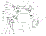
FIG. 1 is a perspective view of the structure of the present invention;
FIG. 2 is an internal perspective view of a toilet body of the present invention construction;
FIG. 3 is a perspective view of the assembled toilet body according to the present invention;
FIG. 4 is an enlarged view of portion A of FIG. 1 in accordance with the present invention;
FIG. 5 is a schematic perspective view of the hand washing basin according to the present invention;
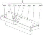
FIG. 6 is a schematic view of a part of a fastening device in the hand sink according to the present invention;
FIG. 7 is a schematic bottom view of the hand sink of FIG. 6 according to the present invention;
FIG. 8 is a schematic view of the structure at the position A in FIG. 5 in the hand washing basin according to the present invention;
FIG. 9 is a schematic perspective view of a cleaning device in a sink according to the present invention;
FIG. 10 is a schematic rear view of the hand sink of FIG. 9 in accordance with the present invention;
FIG. 11 is a schematic perspective view of an auxiliary device in a hand washing basin according to the present invention;
FIG. 12 is a schematic view of a storage structure of the body of the hand washing sink according to the present invention;
fig. 13 is a schematic cross-sectional structure of the body of the hand washing sink according to the present invention.
Detailed Description
The technical solutions in the embodiments of the present invention will be clearly and completely described below with reference to the drawings in the embodiments of the present invention, and it is obvious that the described embodiments are only a part of the embodiments of the present invention, and not all of the embodiments. All other embodiments, which can be derived by a person skilled in the art from the embodiments given herein without making any creative effort, shall fall within the protection scope of the present invention.
Example one
Referring to fig. 1-4, the present invention provides a technical solution: a movable modularized facility comprises a toilet body 1a, a sealing door 3a is installed on the front face of the toilet body 1a through a strong hinge 2a, a squatting pan 4a is installed on the inner bottom wall of the toilet body 1a, a toilet bowl 5a is installed on the right inner wall of the toilet body 1a, a flushing water tank 6a is installed on the rear inner wall of the toilet body 1a, the squatting pan 4a and the toilet bowl 5a are communicated with the flushing water tank 6a, the squatting pan 4a and the toilet bowl 5a are both connected with an external excrement collecting device, a manual button 7a is arranged on the flushing water tank 6a, anti-skid foot pads 8a are fixedly connected to the two sides of the top of the squatting pan 4a, a toilet cover 9a matched with the toilet bowl cover is movably installed on the toilet bowl 5a through a pin shaft, a base 10a is fixedly installed at the bottom of the toilet body 1a, and installation grooves 11a are formed in the four corners of the, an electric telescopic rod 12a is fixedly mounted at the bottom of the mounting groove 11a, a dust-proof tool 13a is fixedly connected to the bottom end of the electric telescopic rod 12a, and a shifting roller 14a is movably mounted on the dust-proof tool 13 a.
The inner wall of the mounting groove 11a is provided with a slide rail 15a, the surface of the dust guard 13a is fixedly connected with a reinforcing rod 16a, and the other end of the reinforcing rod 16a penetrates through the slide rail 15a and is connected with another adjacent dust guard 13 a.
The inner wall of the toilet body 1a is provided with a ventilation net groove 17a, and the surface of the sealing door 3a is provided with a transparent light port 18 a.
The surface of the sealing door 3a is fixedly connected with a door handle 19a, and a protection pad is sleeved on the door handle 19 a.
A hand washing basin 20a is installed on the left inner wall of the toilet body 1a, a water storage tank 21a is installed at the bottom of the hand washing basin 20a, a toilet paper tube 23a is installed on the hand washing basin 20a, and cleaning paper is arranged in the toilet paper tube 23 a.
The top of the toilet body 1a is fixedly provided with a solar light panel 24a, the inner top wall of the toilet body 1a is provided with a storage battery 25a, and the bottom of the storage battery 25a is provided with an LED lamp 26 a.
The solar panel 24a is laid with a transparent drainage layer, and the top of the transparent drainage layer is convex.
The solar light panel 24a is electrically connected to the battery 25a and the LED lamp 26a, respectively.
The toilet body 1a can be formed by combining two toilets, and male and female marks 27a are arranged on the sealing doors 3a of the two toilets.
The reservoir 21a is connected to a connecting pipe 22a, and the other end of the connecting pipe 22a is connected to the flush tank 6a through a check valve.
The working principle is as follows: when the toilet body 1a is placed, the electric telescopic rod 12a can be started, the electric telescopic rod 12a is controlled to contract, the electric telescopic rod 12a drives the dustproof tool 13a to move upwards, so that the displacement roller 14a is completely contracted into the mounting groove 11a, at the moment, the displacement roller 14a is separated from the ground, the base 10a supports the toilet body 1a, the placement of the toilet body 1a is more stable, and the subsequent use is facilitated, and in the process that the dustproof tool 13a moves upwards, the dustproof tool 13a drives the reinforcing rod 16a to slide in the sliding rail 15a, so that the moving stability of the dustproof tool 13a is improved, and the stability of the displacement roller 14a is improved; similarly, when the toilet needs to move, the electric telescopic rod 12a is controlled to extend, the electric telescopic rod 12a drives the dust-proof tool 13a to move downwards, so that the displacement rollers 14a are in contact with the ground, then the electric telescopic rod 12a still extends, the toilet body 1a is slightly jacked up, and at the moment, the base 10a is separated from the ground, so that the four displacement rollers 14a can exert the effect of convenient movement; when the toilet body 1a is used, the door handle 19a is held by a hand to open the sealing door 3a, the squatting pan 4a and the toilet pan 6a in the toilet body 1a can be used, so that the flexibility is better, the manual button 7a can be pressed when the toilet is used, so that water in the flushing water tank 6a can flush the squatting pan 4a and the toilet pan 5a, the toilet is kept clean, the ventilation net groove 17a enables air in the toilet body 1a to be in convection with external air, peculiar smell in the toilet body 1a is avoided, and the cleanness is improved; the hand washing basin 20a can wash hands, washing water after washing the hands flows into the water storage tank 21a, the washing water is conveyed into the flushing water tank 6a through the water storage tank 21a through the connecting pipe 22a, the one-way valve enables the washing water to only enter the water storage tank 21a and not to flow out of the water storage tank 21a through the one-way valve, water resources after washing the hands can be recovered and used for flushing a toilet, the water saving concept is advocated, cleaning paper extraction can be arranged in the toilet paper barrel 23a, the toilet paper barrel is convenient to use, and the embarrassing situation that people forget to carry paper is avoided; because the toilet body 1a is outdoors for a long time, the solar light panel 24a can absorb solar energy and convert the solar energy into electric energy for the storage battery 25a to use, and the storage battery 25a can start the LED lamp 26a, so that the LED lamp 26a can illuminate for use at night, thereby saving energy and protecting environment; the toilet body 1a can be composed of two toilets, and the toilet is provided with a male and female mark 27a to warn people to use the toilet correctly, avoid the scene of disordered use and improve the safety consciousness.
Example two
Referring to fig. 1-13, the present invention provides a technical solution: a mobile modular facility comprising: a toilet body 1a, a sealing door 3a is installed on the front surface of the toilet body 1a through a strong hinge 2a, a squatting pan 4a is installed on the inner bottom wall of the toilet body 1a, a toilet bowl 5a is installed on the right inner wall of the toilet body 1a, a flushing water tank 6a is installed on the rear inner wall of the toilet body 1a, the squatting pan 4a and the toilet bowl 5a are both communicated with the flushing water tank 6a, the squatting pan 4a and the toilet bowl 5a are both connected with an external excrement collecting device, a manual button 7a is arranged on the flushing water tank 6a, anti-skid foot pads 8a are fixedly connected on both sides of the top of the squatting pan 4a, a toilet cover 9a matched with the toilet bowl cover is movably installed on the toilet bowl 5a through a pin shaft, a base 10a is fixedly installed on the bottom of the toilet body 1a, installation grooves 11a are formed in four corners of the bottom of the base 10a, and an electric telescopic, and the bottom end of the electric telescopic rod 12a is fixedly connected with a dustproof tool 13a, and a shifting roller 14a is movably arranged on the dustproof tool 13 a.
A hand washing sink 20a is arranged on the left inner wall of the toilet body 1 a. Preferably, the hand washing basin 20a comprises a body 1 and a clamping device 7, the body 1 is a hand washing platform, a telescopic rod 10 is fixedly connected inside the body 1, and a push plate 4 is fixedly connected to one end, far away from the body 1, of the telescopic rod 10. The end, close to the body 1, of the push plate 4 is fixedly connected with the hand basin 13, at the moment, the telescopic rod 10 contracts to enable the hand basin 13 to be retracted into the body 1, at the moment, the disc 711 is loosened to enable the first spring 712 to pull the disc 711 due to the elastic force recovery, the disc 711 pushes the clamping column 714 by means of the tensile force of the first spring 712 to enable the clamping column 714 to slide into the clamping groove 705, at the moment, the connecting rod 703 is fixed by means of the clamping block and the clamping groove 705, the connecting rod 703 always blocks the push plate 4, so that the push plate 4 always extrudes the hand basin 13 into the body 1 to achieve the effect of storing the hand basin 13, when the hand basin 13 needs to be used, the disc 711 is pulled to enable the clamping column 714 to be pulled to enable the clamping column 714 to slide out of the clamping groove 705, then the push plate 4 is pulled to enable the push plate 4 not to block the hand basin 13, when the push plate 4 needs to be closed, the disc 711 is pulled to pull the clamping column 714, then the clamping plate 701 is pulled to slide the clamping plate 701 out of the limiting block 702, at the moment, the sliding rod 709 is pushed to push the limiting block 702 by means of thrust, the connecting rod 703 drives the rotating column 706 to rotate on the fixed block 707 by means of the thrust of the limiting block 702, meanwhile, the connecting rod 703 pushes the push plate 4, the push plate 4 simultaneously pushes the telescopic rod 10 and the hand basin 13 by means of the thrust of the connecting rod 703, the hand basin 13 is contracted by means of the thrust because the hand basin 13 is made of rubber, the top end of the body 1 is rotatably connected with the first water faucet 5, one end of the body 1 close to the first water faucet 5 is rotatably connected with the second water faucet 6, one ends of the first water faucet 5 and the second water faucet 6 close to the body 1 are communicated with the water pipe 11, one side of the body 1 is slidably connected with a placing block 3, one side of the placing block 3 close to the body 1 is uniformly and fixedly connected with a placing frame 2, one side of the hand washing table close to the push plate 4 is provided with a clamping device 7, the clamping device 7 comprises a fixed block 707, one side of the fixed block 707 far away from the push plate 4 is fixedly connected with a connecting column 710, one end of the connecting column 710 far away from the fixed block 707 is fixedly connected with a connecting plate 708, one end of the connecting plate 708 far away from the connecting rod 703 is slidably connected with a clamping plate 701, the clamping plate 701 is U-shaped, one end of the clamping plate 701 far away from the connecting plate 708 is slidably connected with the inside of a limiting block 702, a sliding rod 709 is inserted in the connecting plate 708 in a penetrating manner, one end of the sliding rod 709 close to a connecting block 713 is fixedly connected with a limiting block 702, the limiting block 702 is U-shaped, the surface of the rotary column 706 is fixedly connected with a connecting rod 703, so that the basin 13 is restored to the original shape, meanwhile, the push plate 4 pushes the connecting rod 703, so that the connecting rod 703 is contacted with the limiting block 702, then the push plate 701 is pushed to enable the clamping plate 701 to slide into the limiting block 702, so that the connecting rod 703 is fixed by the clamping of the clamping plate 701 and the limiting block 702, the basin 13 is opened, one end of the connecting rod 703, which is far away from the fixing block 707, is fixedly connected with a rectangular block 704, one end of the rectangular block 704, which is far away from the connecting rod 703, is provided with a clamping groove 705, one end of the push plate 4, which is far away from the body 1, is fixedly connected with a connecting block 713, a clamping column 714 is inserted in the connecting block 713 in a penetrating manner, one end of the clamping column 714, which is far away from the placing block 3, the surface of the post 714 engages the slot 705.
The whole clamping device 7 has the effects that by arranging the clamping device 7, when the push plate 4 needs to be closed, the disc 711 is pulled firstly to enable the disc 711 to pull the clamping column 714, then the clamping plate 701 is pulled to enable the clamping plate 701 to slide out of the inside of the limiting block 702, at the moment, the sliding rod 709 is pushed to enable the sliding rod 709 to push the limiting block 702 by means of pushing force, the connecting rod 703 drives the rotating column 706 to rotate on the fixing block 707 by means of the pushing force of the limiting block 702, meanwhile, the connecting rod 703 can push the push plate 4 to enable the push plate 4 to push the telescopic rod 10 and the hand basin 13 by means of the pushing force of the connecting rod 703, because the hand basin 13 is made of rubber, the hand basin 13 can be contracted by means of the pushing force, at the moment, the telescopic rod 10 can be contracted to enable the hand basin 13 to be retracted into the body 1, at the moment, the disc 711 is released to enable the, so that the clamping column 714 slides into the clamping groove 705, at the moment, the connecting rod 703 is clamped and fixed by the clamping block and the clamping groove 705, the connecting rod 703 always blocks the push plate 4, so that the push plate 4 always extrudes the hand basin 13 inside the body 1 to play a role of storing the hand basin 13, when the hand basin 13 needs to be used, the disc 711 is pulled to pull the clamping column 714 so that the clamping column 714 slides out of the clamping groove 705, then the push plate 4 is pulled so that the push plate 4 does not block the hand basin 13, so that the hand basin 13 restores to the original shape, meanwhile, the connecting rod 703 is pushed by the push plate 4 so that the connecting rod 703 is in contact with the limiting block 702, then the clamping plate 701 is pushed to slide into the limiting block 702, so that the connecting rod is fixed by the clamping of the clamping plate 701 and the limiting block 702, the function of opening the hand basin 13 is achieved, thereby solving the problem that the traditional fixing is generally directly clamping drawer, the drawer and the place where washing hands are clamped are loosened after long-time use, so that the washing basin cannot be stored.
One end of the body 1 close to the first water tap 5 is provided with a cleaning device 8, the cleaning device 8 comprises a fixing plate 801, one end of the fixing plate 801 far away from the sponge block 803 is fixedly connected with a supporting plate 802, a push rod 809 is inserted into the inside of the supporting plate 802, the push rod 809 is pushed to enable the push rod 809 to push a slider 811, at this time, two sides of the slider 811 can be in contact with the supporting rod 806, and two sides of the slider 811 can push the supporting rod 806 to enable the supporting rod 806 to pull a push block 805 by virtue of the push force of the slider 811, so that the push block 805 is not squeezing the sponge block 803, a spring rotates a threaded rod 810 to enable the threaded rod 810 to rotate into the inside of the push rod 809, so that the slider 811 is fixedly connected with the push rod 809 by virtue of the threaded rod 810, one end of the push rod 809 close to the supporting rod 806, then the sponge block 803 is used for cleaning the water drops on the body 1, the function of cleaning the water drops on the body 1 is achieved, then the used sponge block 803 is placed on the placing plate 804, the threaded rod 810 is rotated to enable the threaded rod 810 to rotate out of the interior of the push rod 809, the second spring 808 pulls the supporting rod 806 due to the elastic force recovery, the supporting rod 806 pushes the push block 805 through the pulling of the second spring 808, the push block 805 is in contact with the sponge block 803, the sponge block 803 is fixed on the placing plate 804 through the pushing force of the push block 805, the function of fixing the sponge block 803 is achieved, the sliding block 811 is in a ladder shape, two sides of the sliding block 811 are in contact with the supporting rod 806, the threaded rod 810 is inserted into one end, far away from the fixing plate 801, of the supporting plate 802, the threaded rod 810 is inserted into the interior of the push rod 809, one side of the fixing plate 801 is fixedly connected with the body 1, one side, close to the first faucet, place the board 804 and keep away from the one end of body 1 and contact sponge piece 803, the both sides fixedly connected with rectangular plate 807 of fixed plate 801, rectangular plate 807 is "U" font, the inner wall fixedly connected with second spring 808 of rectangular plate 807, the one end fixedly connected with bracing piece 806 of rectangular plate 807 is kept away from to second spring 808, bracing piece 806 is "L" shape, and the forearm fixedly connected with ejector pad 805 of bracing piece 806, one side that bracing piece 806 was kept away from to ejector pad 805 contacts with sponge piece 803.
The whole cleaning device 8 has the effects that by arranging the cleaning device 8, when water drops on the main body need to be cleaned, the push rod 809 is pushed to enable the push rod 809 to push the sliding block 811, at the moment, two sides of the sliding block 811 can be in contact with the supporting rod 806, and two sides of the sliding block 811 can push the supporting rod 806, so that the supporting rod 806 pulls the push block 805 by virtue of the thrust of the sliding block 811, the push block 805 does not extrude the sponge block 803, the spring rotates the threaded rod 810 again to enable the threaded rod 810 to rotate into the push rod 809, the sliding block 811 is fixedly connected with the push rod 809 by virtue of the threaded rod 810, the sliding block 811 always blocks the supporting rod 806, then the sponge block 803 on the placing plate 804 is taken away, the water drops on the body 1 are cleaned by virtue of the sponge block 803, the function of cleaning the water drops on the body 1 is achieved, and then the used sponge block 803 is placed on the placing plate 804, the threaded rod 810 is rotated again, so that the threaded rod 810 is rotated out from the interior of the push rod 809, the second spring 808 pulls the supporting rod 806 due to the elastic force recovery, the supporting rod 806 pushes the push block 805 by virtue of the pulling of the second spring 808, the push block 805 is contacted with the sponge block 803, the sponge block 803 is fixed on the placing plate 804 by virtue of the pushing force of the push block 805, the effect of fixing the sponge block 803 is achieved, and the problem that after the hand basin 13 is used, water possibly stays on a hand washing table and the residual water is not cleaned well is solved.
An auxiliary device 9 is arranged on one side of the body 1 far away from the placing block 3, the auxiliary device 9 comprises a rectangular box 93, a supporting block 94 is fixedly connected to a port of the rectangular box 93, the supporting block 94 is L-shaped, a limit plate 95 is inserted through a short arm end of the supporting block 94, the limit plate 95 is T-shaped, a handle 97 is fixedly connected to one side of the baffle 96 close to the supporting block 94, the handle 97 is U-shaped, one side of the handle 97 far away from the rectangular box 93 is in contact with the limit plate 95, one side of the rectangular box 93 is fixedly connected with the body 1, two third springs 92 are fixedly connected to the inner wall of the rectangular box 93, one ends of the two third springs 92 far away from the rectangular box 93 are fixedly connected with a storage box 91, soap is firstly placed in the storage box 91, when the soap needs to be used, the soap is taken out from the storage box 91, the soap is placed in the storage box 91 after the soap passes, and then the, then, the limiting plate 95 is pulled again to enable the limiting plate 95 to slide in the supporting block 94, then the handle 97 is pushed again to enable the handle 97 to drive the baffle 96, the baffle 96 blocks the rectangular box 93, at the moment, the limiting plate 95 is loosened to enable the limiting plate 95 to slide in the supporting block 94 due to gravity, the limiting plate 95 blocks the handle 97 is enabled to penetrate through the storage box 91, the baffle 96 is inserted in the storage box 91, soap in the storage box 91 is fixed in the rectangular box 93 by means of the force of the baffle 96 for blocking the storage box 91, when the soap needs to be used, the limiting plate 95 is pulled again to enable the limiting plate 95 to slide in the supporting block 94, the limiting plate 95 does not block the handle 97, then the handle 97 is pulled back to enable the handle 97 to drive the baffle 96, the baffle 96 does not block the storage box 91, at the moment, the storage box 91 is pushed by the third spring 92 due, at this time, the soap in the storage case 91 is taken out for use, and the baffle 96 is brought into contact with the storage case 91 on the side close to the third spring 92.
The integral working principle is that by arranging the auxiliary device 9, soap is firstly placed in the storage box 91, when the soap needs to be used, the soap is taken out of the storage box 91, the soap is placed in the storage box 91 after the soap passes, then the storage box 91 is pressed to enable the storage box 91 to be retracted into the rectangular box 93, then the limiting plate 95 is pulled to enable the limiting plate 95 to slide in the supporting block 94, then the handle 97 is pushed to enable the handle 97 to drive the baffle 96, the baffle 96 blocks the rectangular box 93, at the moment, the limiting plate 95 is loosened to enable the limiting plate 95 to slide in the supporting block 94 due to gravity, the limiting plate 95 blocks the handle 97, the soap in the storage box 91 is fixed in the rectangular box 93 by means of the force of the baffle 96 for blocking the storage box 91, when the soap needs to be used, then the limiting plate 95 is pulled to enable the limiting plate 95 to slide in the supporting, make limiting plate 95 not stopping handle 97, then pull handle 97 behind again and make handle 97 drive baffle 96, make baffle 96 not stopping receiver 91, third spring 92 promotes receiver 91 because the recovery of elasticity this moment, make receiver 91 pop out from rectangle box 93, the soap in receiver 91 is taken out the use again this moment, the effect of taking out soap has been played, thereby the in-process of washing hand has been solved, the problem of laying on wash platform is not good to the soap of use.
Preferably, the solar light panel 24a is fixedly mounted on the top of the toilet body 1a, the storage battery 25a is mounted on the inner top wall of the toilet body 1a, and the LED lamp 26a is mounted on the bottom of the storage battery 25 a.
Preferably, a transparent drainage layer is laid on the solar panel 24a, and the top of the transparent drainage layer is convex.
Preferably, the solar light panel 24a is electrically connected to the storage battery 25a and the LED lamp 26a, respectively.
The toilet body 1a can be formed by combining two toilets, and male and female marks 27a are arranged on the sealing doors 3a of the two toilets.
Preferably, a connecting pipe 22a is connected to the reservoir 21a, and the other end of the connecting pipe 22a is connected to the flush tank 6a through a check valve.
The working principle is as follows: when the toilet body 1a is placed, the electric telescopic rod 12a can be started, the electric telescopic rod 12a is controlled to contract, the electric telescopic rod 12a drives the dustproof tool 13a to move upwards, so that the displacement roller 14a is completely contracted into the mounting groove 11a, at the moment, the displacement roller 14a is separated from the ground, the base 10a supports the toilet body 1a, the placement of the toilet body 1a is more stable, and the subsequent use is facilitated, and in the process that the dustproof tool 13a moves upwards, the dustproof tool 13a drives the reinforcing rod 16a to slide in the sliding rail 15a, so that the moving stability of the dustproof tool 13a is improved, and the stability of the displacement roller 14a is improved; similarly, when the toilet needs to move, the electric telescopic rod 12a is controlled to extend, the electric telescopic rod 12a drives the dust-proof tool 13a to move downwards, so that the displacement rollers 14a are in contact with the ground, then the electric telescopic rod 12a still extends, the toilet body 1a is slightly jacked up, and at the moment, the base 10a is separated from the ground, so that the four displacement rollers 14a can exert the effect of convenient movement; when the toilet body 1a is used, the door handle 19a is held by a hand to open the sealing door 3a, the squatting pan 4a and the toilet pan 6a in the toilet body 1a can be used, so that the flexibility is better, the manual button 7a can be pressed when the toilet is used, so that water in the flushing water tank 6a can flush the squatting pan 4a and the toilet pan 5a, the toilet is kept clean, the ventilation net groove 17a enables air in the toilet body 1a to be in convection with external air, peculiar smell in the toilet body 1a is avoided, and the cleanness is improved; the hand washing basin 20a can wash hands, washing water after washing the hands flows into the water storage tank 21a, the washing water is conveyed into the flushing water tank 6a through the water storage tank 21a through the connecting pipe 22a, the one-way valve enables the washing water to only enter the water storage tank 21a and not to flow out of the water storage tank 21a through the one-way valve, water resources after washing the hands can be recovered and used for flushing a toilet, the water saving concept is advocated, cleaning paper extraction can be arranged in the toilet paper barrel 23a, the toilet paper barrel is convenient to use, and the embarrassing situation that people forget to carry paper is avoided; because the toilet body 1a is outdoors for a long time, the solar light panel 24a can absorb solar energy and convert the solar energy into electric energy for the storage battery 25a to use, and the storage battery 25a can start the LED lamp 26a, so that the LED lamp 26a can illuminate for use at night, thereby saving energy and protecting environment; the toilet body 1a can be composed of two toilets, and the toilet is provided with a male and female mark 27a to warn people to use the toilet correctly, avoid the scene of disordered use and improve the safety consciousness.
Those not described in detail in this specification are within the skill of the art.
Although the present invention has been described in detail with reference to the foregoing embodiments, it will be apparent to those skilled in the art that various changes in the embodiments and/or modifications of the invention can be made, and equivalents and modifications of some features of the invention can be made without departing from the spirit and scope of the invention.
Claims (10)
1. A mobile modular facility comprising a toilet body, characterized in that: the front surface of the toilet body is provided with a sealing door through a powerful hinge, the inner bottom wall of the toilet body is provided with a squatting pan, and the right inner wall of the toilet body is provided with a toilet bowl, the rear inner wall of the toilet body is provided with a flushing tank, the squatting pan and the pedestal pan are both communicated with a flushing water tank, the squatting pan and the pedestal pan are both connected with an external excrement collecting device, a manual button is arranged on the flushing water tank, anti-skid foot pads are fixedly connected with both sides of the top of the squatting pan, the toilet bowl is movably provided with a toilet cover matched with the toilet bowl through a pin shaft, the bottom of the toilet body is fixedly provided with a base, and the four corners of the bottom of the base are all provided with mounting grooves, the bottom of each mounting groove is fixedly provided with an electric telescopic rod, and the bottom end of the electric telescopic rod is fixedly connected with a dustproof tool, and a shifting roller is movably mounted on the dustproof tool.
2. A mobile modular facility according to claim 1, characterized in that: the inner wall of mounting groove has seted up the slide rail, the fixed surface of dustproof utensil is connected with the stiffener, and the other end of stiffener runs through the slide rail and links to each other with adjacent another dustproof utensil.
3. A mobile modular facility according to claim 1, characterized in that: the inner wall of the toilet body is provided with a ventilation net groove, and the surface of the sealing door is provided with a transparent light port.
4. A mobile modular facility according to claim 1, characterized in that: the surface of the sealing door is fixedly connected with a door handle, and a protection pad is sleeved on the door handle.
5. A mobile modular facility according to claim 1, characterized in that: the bathroom body is installed on the left inner wall and is washed hand the pond, and wash hand the bottom in pond and install the water storage box, wash hand and install the toilet paper section of thick bamboo on the pond, and the toilet paper section of thick bamboo embeds there is clean paper extraction.
6. A mobile modular facility according to claim 1, characterized in that: the top fixed mounting of bathroom body has the solar light panel, the battery is installed to the interior roof of bathroom body, and the bottom of battery installs the LED lamp.
7. A mobile modular facility according to claim 6, characterized in that: a transparent drainage layer is laid on the solar panel, and the top of the transparent drainage layer is convex.
8. A mobile modular facility according to claim 6, characterized in that: the solar light panel is respectively electrically connected with the storage battery and the LED lamp.
9. A mobile modular facility according to claim 1, characterized in that: the toilet body can be formed by combining two toilets, and male and female marks are arranged on the sealing doors of the two toilets.
10. A mobile modular facility according to claim 5, characterized in that: the water storage tank is communicated with a connecting pipe, and the other end of the connecting pipe is communicated with the flushing water tank through a one-way valve.
Priority Applications (1)
| Application Number | Priority Date | Filing Date | Title |
|---|---|---|---|
| CN202110009606.1A CN112814098A (en) | 2021-01-05 | 2021-01-05 | Mobile modular facility |
Applications Claiming Priority (1)
| Application Number | Priority Date | Filing Date | Title |
|---|---|---|---|
| CN202110009606.1A CN112814098A (en) | 2021-01-05 | 2021-01-05 | Mobile modular facility |
Publications (1)
| Publication Number | Publication Date |
|---|---|
| CN112814098A true CN112814098A (en) | 2021-05-18 |
Family
ID=75857532
Family Applications (1)
| Application Number | Title | Priority Date | Filing Date |
|---|---|---|---|
| CN202110009606.1A Withdrawn CN112814098A (en) | 2021-01-05 | 2021-01-05 | Mobile modular facility |
Country Status (1)
| Country | Link |
|---|---|
| CN (1) | CN112814098A (en) |
Cited By (1)
| Publication number | Priority date | Publication date | Assignee | Title |
|---|---|---|---|---|
| CN113802650A (en) * | 2021-09-15 | 2021-12-17 | 滁州市永通交通设备有限公司 | Glass fiber reinforced plastic wash basin cabinet and matched hand washer thereof |
Citations (5)
| Publication number | Priority date | Publication date | Assignee | Title |
|---|---|---|---|---|
| KR101564970B1 (en) * | 2015-03-24 | 2015-11-03 | (주)토토 | A movable toilet having multi-function |
| CN107035168A (en) * | 2017-05-24 | 2017-08-11 | 江苏美鑫源绿色房屋有限公司 | A kind of environmental protection type moving lavatory |
| CN207260655U (en) * | 2017-08-30 | 2018-04-20 | 深圳市华基建筑新材料有限公司 | A kind of energy saving and environment friendly mobile washroom |
| CN110858449A (en) * | 2018-08-26 | 2020-03-03 | 江苏信泰照明科技有限公司 | Temporary traffic light convenient to fix and move |
| CN210636534U (en) * | 2019-06-14 | 2020-05-29 | 天津简氏环保技术有限公司 | Ecological environment-friendly mobile toilet |
-
2021
- 2021-01-05 CN CN202110009606.1A patent/CN112814098A/en not_active Withdrawn
Patent Citations (5)
| Publication number | Priority date | Publication date | Assignee | Title |
|---|---|---|---|---|
| KR101564970B1 (en) * | 2015-03-24 | 2015-11-03 | (주)토토 | A movable toilet having multi-function |
| CN107035168A (en) * | 2017-05-24 | 2017-08-11 | 江苏美鑫源绿色房屋有限公司 | A kind of environmental protection type moving lavatory |
| CN207260655U (en) * | 2017-08-30 | 2018-04-20 | 深圳市华基建筑新材料有限公司 | A kind of energy saving and environment friendly mobile washroom |
| CN110858449A (en) * | 2018-08-26 | 2020-03-03 | 江苏信泰照明科技有限公司 | Temporary traffic light convenient to fix and move |
| CN210636534U (en) * | 2019-06-14 | 2020-05-29 | 天津简氏环保技术有限公司 | Ecological environment-friendly mobile toilet |
Cited By (1)
| Publication number | Priority date | Publication date | Assignee | Title |
|---|---|---|---|---|
| CN113802650A (en) * | 2021-09-15 | 2021-12-17 | 滁州市永通交通设备有限公司 | Glass fiber reinforced plastic wash basin cabinet and matched hand washer thereof |
Similar Documents
| Publication | Publication Date | Title |
|---|---|---|
| CN112814098A (en) | Mobile modular facility | |
| CN213742530U (en) | Novel energy-saving public toilet | |
| CN202355332U (en) | Stink-free water-saving sanitary toilet | |
| JP3220712U (en) | Toilet with modularized vacuum hygiene system | |
| CN112761220A (en) | Novel wash device and modular system | |
| CN201665902U (en) | Automatic control system of public washroom | |
| CN110338692A (en) | Stool and urine independence automatic packaging waterless closestool and its operating method | |
| CN110902200B (en) | Integrated garbage recycling device for mobile toilet | |
| CN210238702U (en) | Drainage seat for municipal road | |
| CN212502137U (en) | Dustbin with cover convenient for internal cleaning | |
| CN219622373U (en) | Portable public health | |
| CN2629613Y (en) | Moveable hand-washing device | |
| CN211286796U (en) | Zero-consumption sustainable public health lifting space | |
| CN215857455U (en) | Clear up bridge floor low-lying ponding device fast | |
| CN214885874U (en) | High-efficient automatically cleaning lavatory | |
| CN212477979U (en) | Multifunctional squatting pan | |
| CN201526174U (en) | Environmental protective toilet for pee | |
| CN216602678U (en) | Multifunctional flushing-free mobile toilet | |
| CN210767035U (en) | Excrement collector | |
| CN213851510U (en) | Wheelchair with self-service pumping, draining and dirt-containing device | |
| CN214884153U (en) | Double-side synchronous translation cleaning mechanism | |
| CN220058221U (en) | Movable vehicle-mounted toilet | |
| CN218622471U (en) | Female riding type urinal | |
| CN2904921Y (en) | Novel foot operated squatting pan | |
| CN2772916Y (en) | Shit-collecting box of trolley and train |
Legal Events
| Date | Code | Title | Description |
|---|---|---|---|
| PB01 | Publication | ||
| PB01 | Publication | ||
| SE01 | Entry into force of request for substantive examination | ||
| SE01 | Entry into force of request for substantive examination | ||
| WW01 | Invention patent application withdrawn after publication |
Application publication date: 20210518 |
|
| WW01 | Invention patent application withdrawn after publication |