CN112809838A - Plank cutting equipment is used in furniture production - Google Patents
Plank cutting equipment is used in furniture production Download PDFInfo
- Publication number
- CN112809838A CN112809838A CN202110040813.3A CN202110040813A CN112809838A CN 112809838 A CN112809838 A CN 112809838A CN 202110040813 A CN202110040813 A CN 202110040813A CN 112809838 A CN112809838 A CN 112809838A
- Authority
- CN
- China
- Prior art keywords
- baffle
- wood board
- plate
- cutting
- base plate
- Prior art date
- Legal status (The legal status is an assumption and is not a legal conclusion. Google has not performed a legal analysis and makes no representation as to the accuracy of the status listed.)
- Withdrawn
Links
Images


Classifications
-
- B—PERFORMING OPERATIONS; TRANSPORTING
- B27—WORKING OR PRESERVING WOOD OR SIMILAR MATERIAL; NAILING OR STAPLING MACHINES IN GENERAL
- B27B—SAWS FOR WOOD OR SIMILAR MATERIAL; COMPONENTS OR ACCESSORIES THEREFOR
- B27B5/00—Sawing machines working with circular or cylindrical saw blades; Components or equipment therefor
- B27B5/16—Saw benches
- B27B5/22—Saw benches with non-feedable circular saw blade
-
- B—PERFORMING OPERATIONS; TRANSPORTING
- B27—WORKING OR PRESERVING WOOD OR SIMILAR MATERIAL; NAILING OR STAPLING MACHINES IN GENERAL
- B27B—SAWS FOR WOOD OR SIMILAR MATERIAL; COMPONENTS OR ACCESSORIES THEREFOR
- B27B25/00—Feeding devices for timber in saw mills or sawing machines; Feeding devices for trees
- B27B25/04—Feeding devices for timber in saw mills or sawing machines; Feeding devices for trees with feed chains or belts
-
- B—PERFORMING OPERATIONS; TRANSPORTING
- B27—WORKING OR PRESERVING WOOD OR SIMILAR MATERIAL; NAILING OR STAPLING MACHINES IN GENERAL
- B27B—SAWS FOR WOOD OR SIMILAR MATERIAL; COMPONENTS OR ACCESSORIES THEREFOR
- B27B29/00—Gripping, clamping, or holding devices for the trunk or log in saw mills or sawing machines; Travelling trunk or log carriages
-
- B—PERFORMING OPERATIONS; TRANSPORTING
- B27—WORKING OR PRESERVING WOOD OR SIMILAR MATERIAL; NAILING OR STAPLING MACHINES IN GENERAL
- B27B—SAWS FOR WOOD OR SIMILAR MATERIAL; COMPONENTS OR ACCESSORIES THEREFOR
- B27B31/00—Arrangements for conveying, loading, turning, adjusting, or discharging the log or timber, specially designed for saw mills or sawing machines
- B27B31/02—Loading equipment for travelling carriages
-
- B—PERFORMING OPERATIONS; TRANSPORTING
- B27—WORKING OR PRESERVING WOOD OR SIMILAR MATERIAL; NAILING OR STAPLING MACHINES IN GENERAL
- B27B—SAWS FOR WOOD OR SIMILAR MATERIAL; COMPONENTS OR ACCESSORIES THEREFOR
- B27B5/00—Sawing machines working with circular or cylindrical saw blades; Components or equipment therefor
- B27B5/29—Details; Component parts; Accessories
Abstract
The invention relates to cutting equipment, in particular to wood board cutting equipment for furniture production. The invention aims to solve the technical problem of providing the wood board cutting equipment which can automatically cut the wood board, does not need manual edge replacement, is time-saving and labor-saving and has high efficiency for furniture production. In order to solve the above technical problems, the present invention provides a furniture production plank cutting apparatus, comprising: the bottom plate is connected with supporting legs; a first baffle plate connected to the leg; the cutting mechanism is connected to the bottom plate; and the conveying mechanism is connected to the first baffle. According to the wood board cutting device, the wood board is conveyed and cut through the matching of the cutting mechanism and the conveying mechanism, the wood board is more stable in cutting through the pressing mechanism, the wood board is prevented from flying out, and the working efficiency is improved.
Description
Technical Field
The invention relates to cutting equipment, in particular to wood board cutting equipment for furniture production.
Background
The wood board is a wood board made of complete wood. The boards are firm and durable, have natural grains, and are the best choice in decoration. The wood board is a material frequently used in home decoration, and when purchasing the wood board, the wood board must be clearly seen and has clear grains, and generally, broken grains are not needed.
People cut the plank at present and place the briquetting plank on a bench usually that the manual work, then the manual work steps on plank one end with the foot, cuts the plank through the manual control drag saw after that, trades the limit through the manual work to it after the one end is accomplished in the cutting, then cuts its other one end, and the cutting needs the manual work to do the action of dragging always like this to still need the manual work to trade the limit cutting, waste time and energy, inefficiency.
Therefore, the wood board cutting equipment for furniture production, which can automatically cut the wood board and does not need manual edge changing, is time-saving and labor-saving and efficient, needs to be researched and developed.
Disclosure of Invention
(1) Technical problem to be solved
The invention aims to overcome the defects that the cutting needs to be carried out by manpower all the time, the edge changing and cutting needs to be carried out by manpower, the time and the labor are wasted, and the efficiency is low.
(2) Technical scheme
In order to solve the above technical problems, the present invention provides a furniture production plank cutting apparatus, comprising: the bottom plate is connected with supporting legs; a first baffle plate connected to the leg; the cutting mechanism is connected to the bottom plate; and the conveying mechanism is connected to the first baffle.
Preferably, the cutting mechanism comprises: a support plate connected to the base plate; a motor frame connected to the base plate; a high-speed response motor mounted on the motor frame; the rotating shaft is rotatably connected to the supporting plate and is connected with the output shaft of the high-speed response motor; and the saw blade is connected to the rotating shaft.
Preferably, the transfer mechanism comprises: the transmission shaft is rotatably connected to the first baffle; two driving wheels are arranged and connected to the transmission shaft and the output shaft of the high-speed response motor; a belt connected to the driving wheel; a first bracket connected to the base plate; the gearbox is arranged on the first bracket, and an output port of the gearbox is connected with the transmission shaft on the front side; and the conveying belt is connected to the transmission shaft and is positioned right behind the saw blades on the two sides.
Preferably, the device further comprises a pressing mechanism, wherein the pressing mechanism comprises: a support pipe connected to the first baffle; a fixing frame connected to the support tube; the supporting block is connected to the fixing frame; a slide bar slidably connected to the support block; the pressing plate is connected to the sliding rod and is positioned right in front of the conveyor belt; and the spring is sleeved between the pressing plate and the supporting block.
Preferably, still include unloading mechanism, unloading mechanism includes: the supporting rod is connected to the first baffle; the blanking box is connected to the supporting rod; the rotating rod is rotatably connected to the blanking box; the second baffle is connected to the rotating rod; and the pull rod is connected to the second baffle.
Preferably, the collecting mechanism is further included, and the collecting mechanism includes: a second bracket connected to the base plate; the waste box is connected to the second bracket; and the collecting box is connected to the bottom plate.
(3) Advantageous effects
The invention achieves the following effects: 1. the wood board cutting machine transports and cuts the wood board through the matching of the cutting mechanism and the conveying mechanism.
2. Thereby it is more stable when making the cutting through hold-down mechanism, prevent the plank departure, improved work efficiency.
3. Thereby not needing the manual work to place the plank on the conveyer belt through unloading mechanism, use manpower sparingly and improved work efficiency.
4. Thereby collect plank rim charge and plank cut off through collecting the mechanism, plank rim charge can carry out a recycle.
Drawings
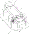
Fig. 1 is a schematic perspective view of the present invention.
Fig. 2 is a schematic perspective view of the cutting mechanism of the present invention.
Fig. 3 is a schematic perspective view of the conveying mechanism of the present invention.
Fig. 4 is a schematic perspective view of the pressing mechanism of the present invention.
Fig. 5 is a schematic perspective view of the blanking mechanism of the present invention.
Fig. 6 is a schematic perspective view of the collecting mechanism of the present invention.
The labels in the figures are: 1-bottom plate, 2-supporting legs, 3-first baffle, 4-cutting mechanism, 41-supporting plate, 42-motor frame, 43-high-speed response motor, 44-rotating shaft, 45-saw blade, 5-conveying mechanism, 51-transmission shaft, 52-transmission wheel, 53-belt, 54-first bracket, 55-gearbox, 56-conveyor belt, 6-pressing mechanism, 61-supporting tube, 62-fixing frame, 63-supporting block, 64-sliding rod, 65-pressing plate, 66-spring, 7-blanking mechanism, 71-supporting rod, 72-blanking box, 73-rotating rod, 74-second baffle, 75-pulling rod, 8-collecting mechanism, 81-second bracket, 82-waste box, 83-collecting box.
Detailed Description
The invention is further described below with reference to the figures and examples.
Example 1
The utility model provides a plank cutting equipment is used in furniture production, as shown in fig. 1-3, including bottom plate 1, landing leg 2, first baffle 3, cutting mechanism 4 and transport mechanism 5, the bottom plate 1 rear portion left and right sides all is connected with two landing legs 2, all is connected with first baffle 3 between the landing leg 2 of the left and right sides, and bottom plate 1 top front side is connected with cutting mechanism 4, is connected with transport mechanism 5 between the first baffle 3 of both sides.
Cutting mechanism 4 is including backup pad 41, motor frame 42, high-speed response motor 43, pivot 44 and saw bit 45, and 1 front side right part of bottom plate is connected with backup pad 41, and 1 front side left part of bottom plate is connected with motor frame 42, and high-speed response motor 43 is installed at motor frame 42 top, and backup pad 41 upper portion rotary type is connected with pivot 44, and pivot 44 and high-speed response motor 43 output shaft all are connected with saw bit 45, the pivot 44 left and right sides.
Conveying mechanism 5 is including transmission shaft 51, drive wheel 52, belt 53, first support 54, gearbox 55 and conveyer belt 56, equal rotary type is connected with transmission shaft 51 between the first baffle 3 front and back both sides of both sides, the transmission shaft 51 and the high-speed response motor 43 output shaft of front side all are connected with drive wheel 52, be connected with belt 53 between the drive wheel 52 of both sides, bottom plate 1 roof front side is connected with first support 54, first support 54 upper portion is equipped with gearbox 55, gearbox 55 delivery outlet is connected with the transmission shaft 51 of front side, be connected with conveyer belt 56 between the transmission shaft 51 of both sides, conveyer belt 56 is located the saw bit 45 dead behind of both sides.
When needs cut the plank, can use this equipment, at first the staff with the plank neatly place on conveyer belt 56, then the manual work starts high-speed response motor 43 and rotates and drive pivot 44 and rotate, pivot 44 rotates and drives saw bit 45 and rotate, high-speed response motor 43 rotates and drives the drive wheel 52 of front side and rotate, the drive wheel 52 of front side rotates and passes through belt 53, thereby drive the drive wheel 52 of rear side and rotate, the drive wheel 52 of rear side rotates and drives the transmission shaft 51 of front side and rotate, the transmission shaft 51 of front side rotates and drives conveyer belt 56 and rotate, thereby carry out the transportation forward to the plank on conveyer belt 56, thereby the plank transports forward and cuts with saw bit 45 contact.
Example 2
On the basis of embodiment 1, as shown in fig. 4, the device further includes a pressing mechanism 6, the pressing mechanism 6 includes a supporting tube 61, a fixing frame 62, supporting blocks 63, sliding rods 64, a pressing plate 65 and springs 66, the supporting tube 61 is connected to the front sides of the first baffles 3 on both sides, the fixing frame 62 is connected to the upper portions of the supporting tubes 61 on both sides, the supporting blocks 63 are connected between the upper portions of the inner sides of the fixing frames 62 on both sides, the two sliding rods 64 are connected to both the left and right sides of the supporting block 63 in a sliding manner, the pressing plate 65 is connected between the sliding rods 64 on both sides, the pressing plate 65 is located right in front of the conveyor belt.
When the wood board is transported forwards, the wood board moves forwards to contact with the pressing plate 65, so that the wood board moves upwards, the springs 66 on the two sides of the upward movement of the pressing plate 65 are compressed, and the wood board is clamped under the action of the compressed springs 66, so that the cutting is more stable, the wood board is prevented from flying out, and the working efficiency is improved.
Example 3
On the basis of embodiment 2, as shown in fig. 5, the blanking device 7 further includes a blanking mechanism 7, the blanking mechanism 7 includes a support rod 71, a blanking box 72, a rotating rod 73, a second baffle 74 and a pull rod 75, the support rod 71 is connected to the outer side of the rear portion of each of the first baffles 3 on both sides, the blanking box 72 is connected between the upper portions of the support rods 71 on both sides, the rotating rod 73 is rotatably connected to the right side of the lower portion of the blanking box 72, the second baffle 74 is connected to the lower portion of the rotating rod 73, and the pull rod 75 is connected to the middle of the right side.
When the plank needs to be cut, a large number of planks are manually placed in the blanking box 72 and then blanked through the manual control pull rod 75, so that the planks do not need to be manually placed on the conveyor belt 56, manpower is saved, and working efficiency is improved.
On the basis of embodiment 2, as shown in fig. 6, the collecting device further comprises a collecting mechanism 8, the collecting mechanism 8 comprises a second bracket 81, a waste bin 82 and a collecting box 83, the left side and the right side of the front part of the bottom plate 1 are both connected with the two second brackets 81, the waste bin 82 is connected between the two second brackets 81 at the two sides, and the front side of the top part of the bottom plate 1 is connected with the collecting box 83.
When the wood board is cut, the wood board scrap can be recycled by providing the scrap box 82 and the collection box 83 so as to collect the cut wood board scrap and the cut wood board.
The above examples are merely representative of preferred embodiments of the present invention, and the description thereof is more specific and detailed, but not to be construed as limiting the scope of the present invention. It should be noted that, for those skilled in the art, various changes, modifications and substitutions can be made without departing from the spirit of the present invention, and these are all within the scope of the present invention. Therefore, the protection scope of the present patent shall be subject to the appended claims.
Claims (6)
1. A plank cutting equipment for furniture production, characterized by includes:
a bottom plate (1) on which legs (2) are connected;
a first baffle (3) connected to the leg (2);
a cutting mechanism (4) connected to the base plate (1);
and a conveying mechanism (5) connected to the first baffle (3).
2. A furniture producing wood cutting apparatus according to claim 1, wherein the cutting mechanism (4) comprises:
a support plate (41) connected to the base plate (1);
a motor frame (42) connected to the base plate (1);
a high-speed response motor (43) mounted on the motor frame (42);
a rotating shaft (44) rotatably connected to the support plate (41), wherein the rotating shaft (44) is connected with an output shaft of the high-speed response motor (43);
and a saw blade (45) connected to the rotating shaft (44).
3. A furniture producing wood cutting apparatus according to claim 2, wherein the conveying mechanism (5) comprises:
a transmission shaft (51) rotatably connected to the first baffle (3);
two transmission wheels (52) are arranged and connected to the transmission shaft (51) and the output shaft of the high-speed response motor (43);
a belt (53) connected to the transmission wheel (52);
a first bracket (54) connected to the base plate (1);
a gearbox (55) arranged on the first bracket (54), wherein the output port of the gearbox (55) is connected with the front transmission shaft (51);
and the conveying belt (56) is connected to the transmission shaft (51), and the conveying belt (56) is positioned right behind the saw blades (45) on the two sides.
4. A furniture producing wood cutting apparatus according to claim 3, further comprising a hold-down mechanism (6), wherein the hold-down mechanism (6) comprises:
a support pipe (61) connected to the first baffle (3);
a fixing frame (62) connected to the support tube (61);
a supporting block (63) connected to the fixing frame (62);
a slide bar (64) slidably connected to the support block (63);
the pressing plate (65) is connected to the sliding rod (64), and the pressing plate (65) is positioned right in front of the conveyor belt (56);
and the spring (66) is sleeved between the pressing plate (65) and the supporting block (63).
5. The furniture production plank cutting apparatus according to claim 4, further comprising a blanking mechanism (7), wherein the blanking mechanism (7) comprises:
a support bar (71) connected to the first baffle (3);
a blanking box (72) connected to the support bar (71);
a rotating rod (73) which is rotatably connected to the blanking box (72);
a second baffle plate (74) connected to the rotating rod (73);
and a pull rod (75) connected to the second baffle plate (74).
6. A furniture production plank cutting apparatus according to claim 5, further comprising a collection mechanism (8), the collection mechanism (8) comprising:
a second bracket (81) connected to the base plate (1);
a waste bin (82) connected to the second bracket (81);
a collecting box (83) connected to the base plate (1).
Priority Applications (1)
| Application Number | Priority Date | Filing Date | Title |
|---|---|---|---|
| CN202110040813.3A CN112809838A (en) | 2021-01-13 | 2021-01-13 | Plank cutting equipment is used in furniture production |
Applications Claiming Priority (1)
| Application Number | Priority Date | Filing Date | Title |
|---|---|---|---|
| CN202110040813.3A CN112809838A (en) | 2021-01-13 | 2021-01-13 | Plank cutting equipment is used in furniture production |
Publications (1)
| Publication Number | Publication Date |
|---|---|
| CN112809838A true CN112809838A (en) | 2021-05-18 |
Family
ID=75869052
Family Applications (1)
| Application Number | Title | Priority Date | Filing Date |
|---|---|---|---|
| CN202110040813.3A Withdrawn CN112809838A (en) | 2021-01-13 | 2021-01-13 | Plank cutting equipment is used in furniture production |
Country Status (1)
| Country | Link |
|---|---|
| CN (1) | CN112809838A (en) |
Cited By (2)
| Publication number | Priority date | Publication date | Assignee | Title |
|---|---|---|---|---|
| CN113290642A (en) * | 2021-06-18 | 2021-08-24 | 蔡厚曦 | Wood board slitting equipment for wood processing |
| CN114290443A (en) * | 2021-12-23 | 2022-04-08 | 梁威峰 | A equipment for cutting of combined material panel |
Citations (9)
| Publication number | Priority date | Publication date | Assignee | Title |
|---|---|---|---|---|
| EP0956932A2 (en) * | 1998-05-14 | 1999-11-17 | Franz Gutser | Device for cutting up elongated work pieces |
| CN103722590A (en) * | 2013-12-30 | 2014-04-16 | 邹建静 | Safe type timber cutting machine with multiple cutting saw blades |
| CN204935808U (en) * | 2015-08-21 | 2016-01-06 | 北京北华丰家具有限公司 | Plank cutting cutter |
| CN208215559U (en) * | 2018-03-29 | 2018-12-11 | 孙周新 | Furniture batten cutting fluting production line |
| CN109531705A (en) * | 2019-01-25 | 2019-03-29 | 尉氏县众林木业有限公司 | Automatic material cutter for waddy processing |
| CN110228109A (en) * | 2019-07-18 | 2019-09-13 | 郭五连 | A kind of wood processing machinery |
| CN110561565A (en) * | 2019-09-20 | 2019-12-13 | 汉德智能科技(徐州)有限公司 | Plank cutting device with retrieve function |
| CN110877370A (en) * | 2019-12-08 | 2020-03-13 | 江西新森岱塑木科技有限公司 | Plastic-wood plate cutting and polishing equipment |
| CN210414838U (en) * | 2019-07-11 | 2020-04-28 | 攀枝花学院 | Automatic log blanking device |
-
2021
- 2021-01-13 CN CN202110040813.3A patent/CN112809838A/en not_active Withdrawn
Patent Citations (9)
| Publication number | Priority date | Publication date | Assignee | Title |
|---|---|---|---|---|
| EP0956932A2 (en) * | 1998-05-14 | 1999-11-17 | Franz Gutser | Device for cutting up elongated work pieces |
| CN103722590A (en) * | 2013-12-30 | 2014-04-16 | 邹建静 | Safe type timber cutting machine with multiple cutting saw blades |
| CN204935808U (en) * | 2015-08-21 | 2016-01-06 | 北京北华丰家具有限公司 | Plank cutting cutter |
| CN208215559U (en) * | 2018-03-29 | 2018-12-11 | 孙周新 | Furniture batten cutting fluting production line |
| CN109531705A (en) * | 2019-01-25 | 2019-03-29 | 尉氏县众林木业有限公司 | Automatic material cutter for waddy processing |
| CN210414838U (en) * | 2019-07-11 | 2020-04-28 | 攀枝花学院 | Automatic log blanking device |
| CN110228109A (en) * | 2019-07-18 | 2019-09-13 | 郭五连 | A kind of wood processing machinery |
| CN110561565A (en) * | 2019-09-20 | 2019-12-13 | 汉德智能科技(徐州)有限公司 | Plank cutting device with retrieve function |
| CN110877370A (en) * | 2019-12-08 | 2020-03-13 | 江西新森岱塑木科技有限公司 | Plastic-wood plate cutting and polishing equipment |
Cited By (2)
| Publication number | Priority date | Publication date | Assignee | Title |
|---|---|---|---|---|
| CN113290642A (en) * | 2021-06-18 | 2021-08-24 | 蔡厚曦 | Wood board slitting equipment for wood processing |
| CN114290443A (en) * | 2021-12-23 | 2022-04-08 | 梁威峰 | A equipment for cutting of combined material panel |
Similar Documents
| Publication | Publication Date | Title |
|---|---|---|
| CN112809838A (en) | Plank cutting equipment is used in furniture production | |
| CN210189969U (en) | Long plate flat cutting machine for polyurethane sponge production | |
| CN113146065B (en) | Laser cutting machine for cutting round steel plate | |
| CN112621840A (en) | Automatic fruit slicing device for food production | |
| CN112705593A (en) | Metal plate bending device for intelligent manufacturing | |
| CN113878772A (en) | Device and method for processing rubber scraps | |
| CN212526288U (en) | Sawing device for bicycle accessories | |
| CN210477046U (en) | Wear-resisting plywood rubber mold cutting machine | |
| CN210552318U (en) | Intermittent limiting mechanism for plastic grain cutting processing equipment | |
| CN216506279U (en) | Device for processing rubber scraps | |
| CN113146743B (en) | Punching and cutting equipment for paperboard production | |
| CN216507025U (en) | Cutting device for woven bag | |
| CN211140890U (en) | Agricultural product production sorting assembly line | |
| CN111015762B (en) | Plastic sheet bending-prevention trimming device | |
| CN209319894U (en) | A kind of surplus material recovery device for corrugated paper production | |
| CN112975157B (en) | Automatic laser cutting device for sheet metal parts | |
| CN215509217U (en) | Cutting device is used in rubber roll production | |
| CN212495104U (en) | Cutting and cutting mechanism for temporary guardrail net production | |
| CN216940970U (en) | Automatic cutting mechanism for production of flexible graphite reinforcing plate | |
| CN212602046U (en) | Chinese patent medicine processing is with medicine cutting machine convenient to equipment | |
| CN219666906U (en) | Automatic feeding mechanism of panel trimming machine | |
| CN220784072U (en) | Corrugated paper slitting device | |
| CN214055633U (en) | Automatic formula china fir cutting mechanism | |
| CN220784082U (en) | Sorting and cutting device for automobile foot pads | |
| CN213890399U (en) | Wooden furniture saw cutting excess material collecting device |
Legal Events
| Date | Code | Title | Description |
|---|---|---|---|
| PB01 | Publication | ||
| PB01 | Publication | ||
| SE01 | Entry into force of request for substantive examination | ||
| SE01 | Entry into force of request for substantive examination | ||
| WW01 | Invention patent application withdrawn after publication | ||
| WW01 | Invention patent application withdrawn after publication |
Application publication date: 20210518 |