CN112809727B - Rope traction rigid-flexible coupling variable-rigidity clamp holder - Google Patents
Rope traction rigid-flexible coupling variable-rigidity clamp holder Download PDFInfo
- Publication number
- CN112809727B CN112809727B CN202110105280.2A CN202110105280A CN112809727B CN 112809727 B CN112809727 B CN 112809727B CN 202110105280 A CN202110105280 A CN 202110105280A CN 112809727 B CN112809727 B CN 112809727B
- Authority
- CN
- China
- Prior art keywords
- flexible
- rigid
- clamping assembly
- assembly
- finger
- Prior art date
- Legal status (The legal status is an assumption and is not a legal conclusion. Google has not performed a legal analysis and makes no representation as to the accuracy of the status listed.)
- Active
Links
Images


Classifications
-
- B—PERFORMING OPERATIONS; TRANSPORTING
- B25—HAND TOOLS; PORTABLE POWER-DRIVEN TOOLS; MANIPULATORS
- B25J—MANIPULATORS; CHAMBERS PROVIDED WITH MANIPULATION DEVICES
- B25J15/00—Gripping heads and other end effectors
- B25J15/08—Gripping heads and other end effectors having finger members
Abstract
The invention provides a rope traction rigid-flexible coupling variable-rigidity gripper, which comprises an inner side flexible mechanism, an outer side rigid gripping mechanism and a driving motor, wherein the inner side flexible mechanism is connected with the outer side rigid gripping mechanism; the inner side flexible mechanism is formed by connecting a flexible left clamping assembly and a flexible right clamping assembly which are symmetrically arranged through a connecting piece; the outer rigid grabbing mechanism comprises a left driving assembly, a right driving assembly, a base, a rigid left clamping assembly and a rigid right clamping assembly which are symmetrically arranged; the flexible left clamping assembly and the flexible right clamping assembly are connected with the base through a connecting piece; one end of the rigid left clamping assembly is connected with the flexible left clamping assembly, and the other end of the rigid left clamping assembly is hinged with the base; one end of the rigid right clamping component is connected with the flexible right clamping component, and the other end of the rigid right clamping component is hinged with the base; and the left driving assembly and the right driving assembly are respectively arranged inside the rigid left clamping assembly and the rigid right clamping assembly and are connected with a driving motor. The gripper has variable-rigidity gripping capability, so that flexible and safe gripping of objects is realized.
Description
Technical Field
The invention relates to the technical field of variable-rigidity clamps, in particular to a rope-traction rigid-flexible coupling variable-rigidity clamp.
Background
The variable-rigidity gripper is used for controlling the rigidity of the gripper, can realize the gripping operation of different complex and fragile objects by changing the rigidity of the gripper under different operating environments, solves the problems of overlarge rigidity of the traditional gripper and insufficient rigidity and gripping force of a soft gripper due to high flexibility of the soft gripper to a certain extent, and has better safety and adaptability. Therefore, the method is widely applied to the fields of intelligent manufacturing, industrial robots and the like mainly based on structural science and intelligent materials.
In the clamping tasks of industry and daily life, on one hand, an end effector of a mechanical arm is often required to perform stable, self-adaptive and variable-rigidity grabbing operations on a fragile object so as to realize safe grabbing of multiple grabbing objects with complex sizes and different shapes; on the other hand, the size of the tail end clamp is required to simulate a human hand and a rope is used for traction as a drive, so that the requirements of lightness, flexibility and low cost can be met in the grabbing process, and the clamping operation with universality, economy and multiple clamping modes is realized. Due to the two reasons, the realization of variable rigidity, hand simulation and rope underactuation simultaneously is a research hotspot in the fields of industrial robots and intelligent manufacturing.
Disclosure of Invention
The invention aims to overcome the defects and shortcomings in the prior art, and provides a rope traction rigid-flexible coupling variable-rigidity gripper which has variable-rigidity gripping capability, so that an object can be gripped flexibly and safely; simultaneously, this holder has advantages such as the size is little, simple structure, with low costs to less driver drive holder joint degree of freedom is favorable to snatching the realization that the object carries out the safety to the many snatching objects that the size is complicated, the shape is different, is fit for being applied to fields such as industrial robot and intelligent manufacturing.
In order to achieve the purpose, the invention is realized by the following technical scheme: the utility model provides a rope pulls rigid-flexible coupling variable rigidity holder which characterized in that: comprises an inner flexible mechanism, an outer rigid grabbing mechanism and a driving motor; the inner side flexible mechanism is formed by connecting a flexible left clamping assembly and a flexible right clamping assembly which are symmetrically arranged through a connecting piece; the outer rigid grabbing mechanism comprises a left driving assembly, a right driving assembly, a base, a rigid left clamping assembly and a rigid right clamping assembly which are symmetrically arranged; the flexible left clamping assembly and the flexible right clamping assembly are connected with the base through a connecting piece; one end of the rigid left clamping assembly is connected with the flexible left clamping assembly, and the other end of the rigid left clamping assembly is hinged with the base; one end of the rigid right clamping component is connected with the flexible right clamping component, and the other end of the rigid right clamping component is hinged with the base; and the left driving assembly and the right driving assembly are respectively arranged inside the rigid left clamping assembly and the rigid right clamping assembly and are connected with a driving motor, so that the driving motor drives the rigid left clamping assembly and the rigid right clamping assembly to clamp or open through the left driving assembly and the right driving assembly.
The flexible left clamping assembly and the flexible right clamping assembly have the same structure and respectively comprise a top end clamping rod, a first double-sided flexible rotating pair, a flexible clamping rod and a second double-sided flexible rotating pair which are sequentially connected; the flexible left clamping assembly and the flexible right clamping assembly are connected with the connecting piece through a second double-sided flexible revolute pair.
The first double-sided flexible revolute pair and the second double-sided flexible revolute pair are both right circular double-sided flexible revolute pairs. The main characteristics of the right circular double-sided flexible revolute pair adopted by the invention are as follows: the flexible kinematic pair has the advantages of simple structure, easy manufacture, no need of assembly and maintenance, no friction loss, and the expression that the topological structure is similar to the corresponding rigidity mechanism, and the traditional kinematic pair is replaced by the multi-concentration flexibility type flexible kinematic pair.
And a tooth-shaped structure for increasing friction force is arranged on the surface of the top end clamping rod.
The inner side flexible mechanism is an integrally formed rubber component. The basic principle of the material selection of the inner flexible mechanism is as follows: first, the ratio of the ultimate strength to the elastic modulus is primarily considered. Such as: polypropylene, polysilicon, rubber, etc. are ideal non-metallic elastic materials. And secondly, the anti-fatigue index of the material is fully considered. Ensuring that the material does not undergo tension relaxation or creep when deformed. Thirdly, in the case where both of the above two points are satisfied, the economical applicability of the material is considered.
The rigid left clamping assembly and the rigid right clamping assembly have the same structure and respectively comprise a tail finger and a root finger which are sequentially hinged; the rigid left clamping assembly is hinged with the flexible left clamping assembly through a tail finger and is hinged with the base through a root finger; the rigid right clamping assembly is hinged with the flexible right clamping assembly through a tail finger and is hinged with the base through a root finger.
The left driving assembly and the right driving assembly have the same structure and respectively comprise an elastic traction device and a transmission device which are arranged in the inner cavities of the tail finger and the root finger; the transmission device is wound around the elastic traction device and penetrates out of the base to be connected with the driving motor.
The elastic traction device comprises a tension rebound spring and a torsion spring; the torsion spring is arranged at the hinge chain of the root finger and the base; one end of the tension rebound spring is fixed on the tail finger, and the other end of the tension rebound spring sequentially bypasses the hinge chain of the tail finger and the root finger and the hinge chain of the root finger and the base and is finally fixed at the joint of the connecting piece and the base to form an extensor tendon structure of the holder.
The transmission device comprises a traction rope, a first wrapping post arranged in the cavity of the tail finger, and a second wrapping post and a third wrapping post which are both arranged in the cavity of the root finger; the first wrapping post and the second wrapping post are arranged close to the hinged chain of the tail finger and the root finger, and the third wrapping post is arranged close to the hinged chain of the root finger and the base;
The traction rope sequentially bypasses the first wrapping post, the hinge chain of the tail finger and the root finger, the second wrapping post, the third wrapping post and the hinge chain of the root finger and the base, and finally penetrates out of the base to be connected with the driving motor to form a flexor tendon structure of the holder.
The traction rope and the tension rebound spring are connected into a whole.
Compared with the prior art, the invention has the following advantages and beneficial effects:
1. the rope-traction rigid-flexible coupling variable-rigidity gripper has variable-rigidity gripping capability, so that objects can be gripped flexibly and safely; simultaneously, this holder has advantages such as the size is little, simple structure, with low costs to less driver drive holder joint degree of freedom is favorable to snatching the realization that the object carries out the safety to the many snatching objects that the size is complicated, the shape is different, is fit for being applied to fields such as industrial robot and intelligent manufacturing.
2. The rope-traction rigid-flexible coupling variable-rigidity gripper disclosed by the invention can realize plane gripping, namely accurate gripping and power gripping, under the open-loop gripping control, is applied to complex hardware, easily-damaged special-shaped parts and the like in the industrial field, is suitable for gripping most of common articles in life, and has better man-machine interaction.
3. The variable rigidity principle realized by rigid-flexible coupling of the gripper disclosed by the invention enables the gripper to adapt to more objects and to accurately grab the objects; the dentate structure of top clamping rod design can carry out the operation that the accuracy was snatched to less, frivolous object, increases the contact friction who snatchs the object simultaneously, increases the success rate of snatching.
4. The rope traction underactuated driving method is simple in structure, similar to a human hand in size, good in self-adaptability, and capable of achieving multiple working modes without a large number of drivers and complex control algorithms.
Drawings
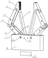
FIG. 1 is a perspective view of a rope-pulling rigid-flexible coupled variable stiffness clamp of the present invention;
FIG. 2 is a perspective view of the flexible mechanism of a rope-pulled rigid-flexible coupled variable stiffness gripper of the present invention;
FIG. 3 is a front view of a rope pulling rigid-flexible coupled variable stiffness clamp of the present invention (and a cross-sectional view of the left clamp and base);
FIG. 4 is a rope path of an elastic traction device of a rope traction rigid-flexible coupled variable stiffness gripper of the present invention;
FIG. 5 is an enlarged view of the top clamping bar of a rope-towed rigid-flexible coupled variable stiffness clamp of the present invention;
FIG. 6 is a schematic diagram of the precise gripping of a rope-towed rigid-flexible coupled variable-stiffness gripper of the present invention;
FIG. 7 is a schematic diagram of a rope-towed rigid-flexible coupled variable stiffness gripper according to the present invention for power gripping;
FIG. 8 is a diagrammatic view of the joint axis of the base and the finger of a rope-pulling rigid-flexible coupled variable stiffness gripper of the present invention;
FIG. 9 is a diagrammatic view of a first, second and third winding post of a rope pulling rigid-flexible coupled variable stiffness clamp of the present invention;
wherein, 1 is a top end clamping rod; 2 is a first double-sided flexible revolute pair; 3 is a flexible clamping rod; 4 is a second double-sided flexible revolute pair; 5 is a connecting piece; 6 is a terminal finger; 7 is a root finger; 8 is a base; 9. 15 are all rivets; 10 is a first wrapping post; 11. 14 are all hinged chains; 12 is a second wrapping post, and 13 is a third wrapping post; 16 is a small hole; 17 is a driving motor; 18 is a tension rebound spring; 19 is a traction rope; 20 is a torsion spring; 21 is a dentate structure; 22 is a micro bearing; 23 is a groove; and 24 is a nut.
Detailed Description
The present invention will be described in further detail with reference to the accompanying drawings and specific embodiments.
Examples
As shown in fig. 1 to 9, the rope-pulling rigid-flexible coupling variable-rigidity gripper comprises an inner flexible mechanism, an outer rigid grabbing mechanism and a driving motor 17, wherein the inner flexible mechanism is formed by connecting a left flexible gripping assembly and a right flexible gripping assembly which are symmetrically arranged through a connecting piece 5. The outer rigid grabbing mechanism comprises a left driving assembly, a right driving assembly, a base 8 and a rigid left clamping assembly and a rigid right clamping assembly which are symmetrically arranged, the flexible left clamping assembly and the flexible right clamping assembly are connected with the base 8 through a connecting piece 5 and a rivet 15, one end of the rigid left clamping assembly is connected with the flexible left clamping assembly through a rivet 9, the other end of the rigid left clamping assembly is hinged with the base 8, one end of the rigid right clamping assembly is connected with the flexible right clamping assembly through the rivet 9, the other end of the rigid right clamping assembly is hinged with the base 8, the left driving assembly and the right driving assembly are respectively arranged inside the rigid left clamping assembly and the rigid right clamping assembly and are connected with a driving motor 17, and the driving motor 17 drives the rigid left clamping assembly and the rigid right clamping assembly to clamp or open through the left driving assembly and the right driving assembly.
Specifically speaking, the flexible left clamping assembly and the flexible right clamping assembly are the same in structure and respectively comprise a top clamping rod 1, a first double-sided flexible revolute pair 2, a flexible clamping rod 3 and a second double-sided flexible revolute pair 4 which are connected in sequence, the flexible left clamping assembly and the flexible right clamping assembly are respectively connected with a connecting piece 5 through the second double-sided flexible revolute pair 4, and the first double-sided flexible revolute pair 2 and the second double-sided flexible revolute pair 4 are both right-circular double-sided flexible revolute pairs. The main characteristics of the right circular double-sided flexible revolute pair adopted by the invention are as follows: the flexible kinematic pair has the advantages of simple structure, easy manufacture, no need of assembly and maintenance, no friction loss, and the expression that the topological structure is similar to the corresponding rigidity mechanism, and the traditional kinematic pair is replaced by the multi-concentration flexibility type flexible kinematic pair.
In order to increase the frictional contact with the object, the surface of the top gripping lever 1 is provided with teeth 21 for increasing the frictional force, which is advantageous for gripping a thin object, such as a coin, in a plane. The function of the fingernail is similar to the function of the hand when the hand of a person accurately pinches the coin.
The inner flexible mechanism is an integrally formed rubber component. The basic principle of the material selection of the inner flexible mechanism is as follows: first, the ratio of the ultimate strength to the elastic modulus is primarily considered. Such as: polypropylene, polysilicon, rubber, etc. are ideal non-metallic elastic materials. And secondly, the anti-fatigue index of the material is fully considered. Ensuring that the material does not undergo tension relaxation or creep when deformed. Thirdly, in the case where both of the above two points are satisfied, the economical applicability of the material is considered.
The rigid left clamping assembly and the rigid right clamping assembly have the same structure and respectively comprise a tail finger 6 and a root finger 7 which are sequentially hinged, the rigid left clamping assembly is hinged with the flexible left clamping assembly through the tail finger 6 and is hinged with the base 8 through the root finger 7, and the rigid right clamping assembly is hinged with the flexible right clamping assembly through the tail finger 6 and is hinged with the base 8 through the root finger 7.
The hinge chain 11 at the joint of the tail finger 6 and the root finger 7 consists of a joint shaft, a miniature bearing and an embedded nut. Two ends of the joint shaft penetrate through the two micro bearings, the inner diameter of each micro bearing is 4mm, the outer diameter of each micro bearing is 6mm, the micro bearings are embedded into joints of the tail fingers 6 and the root fingers 7 respectively, the joint shaft is fixed through the embedded nuts, and the tail fingers 6 are hinged to the root fingers 7. The articulated chain 14 at the joint of the root finger 7 and the base 8 is composed of an articulated shaft, a miniature bearing 22 and an embedded nut. The two ends of the joint shaft are fixed at the outer shell of the base 8 through embedded nuts, the joint shaft penetrates through two miniature bearings 22 embedded at the joint of the root finger 7, and a groove 23 is formed in the joint shaft, so that the root finger 7 of the clamp holder is hinged with the base 8.
The left driving assembly and the right driving assembly have the same structure and respectively comprise an elastic traction device and a transmission device which are arranged in the inner cavities of the tail finger 6 and the root finger 7, and the transmission device is wound around the elastic traction device and penetrates out of the base 8 to be connected with a driving motor 17. Wherein, elastic traction device includes tensile resilience spring 18 and torsional spring 20, and torsional spring 20 sets up in root and indicates 7 articulated chain 14 department with base 8, and torsional spring 20 passes the articulated shaft to install in recess 23, torsional spring 20's one end steel wire is in root and indicates 7 department, and the other end is in base 8 department. When the gripper finishes gripping the object, the base fingers 7 can be controlled to return to the original open position by the self-elasticity of the torsion spring 20.
The tension rebound spring 18 is an elastic element made of elastic material, one end of the tension rebound spring is fixed on the tail finger 6, the other end of the tension rebound spring passes through the joint shaft of the hinge chain 11 of the tail finger 6 and the root finger 7 and the joint shaft of the hinge chain 14 of the root finger 7 and the base 8 in sequence, and the tension rebound spring 18 is parallel to and does not contact with the torsion spring 20. Finally, a tension resilient spring 18 is fixed to rivet 15 where link 5 joins base 8 to form the extensor tendon structure of the holder. The design of the tension resilient spring 18 has an initial state that can satisfy the holding of the gripper open, facilitating the gripping operation of a larger object. The groove 23 of the present invention is for fixing the torsion spring 20 and preventing the extensor or tendon or flexor tendon of the holder from being disturbed by the torsion spring 20.
The transmission device comprises a traction rope 19, a first wrapping post 10 arranged in the inner cavity of the tail finger 6, and a second wrapping post 12 and a third wrapping post 13 which are both arranged in the inner cavity of the root finger 7, wherein the first wrapping post 10 and the second wrapping post 12 are arranged close to a hinged chain 11 of the tail finger 6 and the root finger 7, and the third wrapping post 13 is arranged close to a hinged chain 14 of the root finger 7 and the base 8. And the traction rope 19 sequentially rounds the joint shaft of the hinge chain 11 of the first winding post 10, the tail finger 6 and the root finger 7, the second winding post 12, the third winding post 13 and the joint shaft of the hinge chain 14 of the root finger 7 and the base 8, and finally passes through a preformed hole 16 arranged on the base 8 to be connected with a driving motor 17, so as to form a flexor tendon structure of the gripper. Specifically, the lower side of the first wrapping post 10 contacts with the pulling rope 19, and both ends of the first wrapping post 10 respectively pass through two mutually symmetrical reserved holes on the shell of the tail finger 6 and are fixed by nuts 24. Nuts at two ends are embedded in the shell of the tail finger 6. The lower sides of the second winding post 12 and the third winding post 13 are contacted with a traction rope 19, two ends of the second winding post 12 and the third winding post 13 respectively penetrate through the outer side holes of the root fingers 7, and nuts 24 are embedded in the shells of the root fingers 7.
The invention converts the rotary motion of a driving motor 17 into the plane motion of left and right clamping by a rope traction by a first winding post 10, a second winding post 12 and a third winding post 13 and a joint shaft of an articulated chain. The extensor tendon structure and the flexor tendon structure of the gripper have the characteristics of simple structure, simple principle and low cost, have low requirements on the size of the original part of the formed gripper, have small size and can be made into the size of a human hand.
The pulling rope 19 and the tension rebound spring 18 are connected into a whole, and when the pulling rope and the tension rebound spring pass through the tail finger 6 and the root finger 7, the pulling rope and the tension rebound spring are connected through the bottom end of the tail finger 6, the top end of the root finger 7 and the gap of the base 8. The traction rope 19 is fixed at the top end of the tail finger 6, passes through the lower side of the first winding post 10, the upper end of the hinge chain 11, the lower sides of the second winding post 12 and the third winding post 13 and the upper end of the hinge 14, and penetrates through a reserved hole 16 to be connected with the driving motor 17. The driving motor 17 winds the traction rope by rotating the inner first, second and third winding legs 10, 12 and 13, so that it can generate the contraction of the traction rope 19. The pulling force of the driving motor 17 on the pulling rope 19 reaches the joint shaft of the hinged chain 14 through the reserved hole 16, the joint shaft is in contact with the pulling rope 19, the direction of the pulling force is changed, the pulling force of the pulling rope 19 continues to have an upward force along the direction of the normal line of the tangent line of the pulling rope 19 to the three winding posts, and namely the left clamping assembly has a force closing from left to right. Symmetrically, the right clamping component has a force closing from right to left inwards. The pulling rope 19 passes through the preformed hole 16 of the base vertically as much as possible, so that the friction can be reduced. And the driving motor 17 may be a servo motor, a stepping motor, or the like. The under-actuated driving mode through rope traction has the advantages of simple structure, small size and good self-adaptability, and can realize multiple working modes without a large number of drivers and complex control algorithms.
When the gripper is used for gripping an object, the size of the opening of the gripper is optimally designed according to the two-point gripping and enveloping gripping of the gripped object, and the optimal stretching length of the traction rope and the extensor tendon is obtained. And calculating the gripping force of the required gripper by combining the deformation force of the inner flexible mechanism and the rope tension provided by the motor.
The gripper in the non-working state keeps the maximum state of opening due to the elastic force of the extensor tendon structure, the torsion spring 20 and the inner flexible mechanism. When the gripper works, the driving motor 17 is controlled to rotate forwards, one end of the traction rope 19 is fixed on the rotating shaft of the driving motor 17, and the other end of the traction rope is fixed at the top end of the tail finger 6, so that the traction rope 19 is straightened to generate tension on a flexor tendon structure of the gripper. In this example, the driving motor 17 drives the left and right flexor tendon structures of the gripper at the same time by the rotating shaft, so that the left and right fingers of the gripper are bent at the same time, and the inner flexible mechanism is driven to bend. As shown in fig. 6, when the gripper grips an object with a smaller diameter, the gripper can precisely grip the object, and when the gripper contacts the top end clamping rods 1 of the flexible left gripping assembly and the flexible right gripping assembly, the tail fingers 6 and the root fingers 7 of the rigid left gripping assembly and the rigid right gripping assembly are contracted by the flexor tendon structure to drive the top end clamping rods 1 to grip the object inwards. As shown in fig. 7, when the gripper grips an object with a larger diameter, the object is continuously contacted from the tail finger 6 to the root finger 7 so as to ensure the enveloping grip of the object, and the rigid left gripping assembly and the rigid right gripping assembly are controlled by the driving motor 17 to complete a complete open-loop gripping control. When the gripper releases the gripped object, the drive motor 17 is reversed. The flexor tendon structure is loosened along the original path, and the elastic force of the extensor tendon structure, the torsion spring and the inner flexible mechanism restores the holder to the original state.
The above embodiments are preferred embodiments of the present invention, but the present invention is not limited to the above embodiments, and any other changes, modifications, substitutions, combinations, and simplifications which do not depart from the spirit and principle of the present invention should be construed as equivalents thereof, and all such changes, modifications, substitutions, combinations, and simplifications are intended to be included in the scope of the present invention.
Claims (7)
1. The utility model provides a rope pulls rigid-flexible coupling variable rigidity holder which characterized in that: comprises an inner flexible mechanism, an outer rigid grabbing mechanism and a driving motor; the inner side flexible mechanism is formed by connecting a flexible left clamping assembly and a flexible right clamping assembly which are symmetrically arranged through a connecting piece; the outer rigid grabbing mechanism comprises a left driving assembly, a right driving assembly, a base, a rigid left clamping assembly and a rigid right clamping assembly which are symmetrically arranged; the flexible left clamping assembly and the flexible right clamping assembly are connected with the base through a connecting piece; one end of the rigid left clamping assembly is connected with the flexible left clamping assembly, and the other end of the rigid left clamping assembly is hinged with the base; one end of the rigid right clamping component is connected with the flexible right clamping component, and the other end of the rigid right clamping component is hinged with the base; the left driving assembly and the right driving assembly are respectively arranged in the rigid left clamping assembly and the rigid right clamping assembly and are connected with the driving motor, so that the driving motor drives the rigid left clamping assembly and the rigid right clamping assembly to carry out clamping or stretching movement through the left driving assembly and the right driving assembly;
The rigid left clamping assembly and the rigid right clamping assembly have the same structure and respectively comprise a tail finger and a root finger which are sequentially hinged; the rigid left clamping assembly is hinged with the flexible left clamping assembly through a tail finger and is hinged with the base through a root finger; the rigid right clamping assembly is hinged with the flexible right clamping assembly through a tail finger and is hinged with the base through a root finger;
the left driving assembly and the right driving assembly have the same structure and respectively comprise an elastic traction device and a transmission device which are arranged in the inner cavities of the tail finger and the root finger; the transmission device is wound around the elastic traction device and penetrates out of the base to be connected with the driving motor;
the elastic traction device comprises a tension rebound spring and a torsion spring; the torsion spring is arranged at the hinge chain of the root finger and the base; one end of the tension rebound spring is fixed on the tail finger, and the other end of the tension rebound spring sequentially bypasses the hinge chain of the tail finger and the root finger and the hinge chain of the root finger and the base and is finally fixed at the joint of the connecting piece and the base to form an extensor tendon structure of the holder.
2. The rope pulling rigid-flexible coupling variable stiffness gripper of claim 1, wherein: the flexible left clamping assembly and the flexible right clamping assembly have the same structure and respectively comprise a top end clamping rod, a first double-sided flexible rotating pair, a flexible clamping rod and a second double-sided flexible rotating pair which are sequentially connected; the flexible left clamping assembly and the flexible right clamping assembly are connected with the connecting piece through a second double-sided flexible revolute pair.
3. The rope pulling rigid-flexible coupling variable stiffness gripper of claim 2, wherein: the first double-sided flexible revolute pair and the second double-sided flexible revolute pair are both right circular double-sided flexible revolute pairs.
4. The rope pulling rigid-flexible coupling variable stiffness gripper of claim 2, wherein: and a tooth-shaped structure for increasing friction force is arranged on the surface of the top end clamping rod.
5. The rope pulling rigid-flexible coupling variable stiffness gripper of claim 1, wherein: the inner side flexible mechanism is an integrally formed rubber component.
6. The rope pulling rigid-flexible coupling variable stiffness gripper of claim 1, wherein: the transmission device comprises a traction rope, a first wrapping post arranged in the inner cavity of the tail finger, and a second wrapping post and a third wrapping post which are both arranged in the inner cavity of the root finger; the first wrapping post and the second wrapping post are arranged close to the hinged chain of the tail finger and the root finger, and the third wrapping post is arranged close to the hinged chain of the root finger and the base;
the traction rope sequentially bypasses the first wrapping post, the hinged chain of the tail finger and the root finger, the second wrapping post, the third wrapping post and the hinged chain of the root finger and the base, and finally penetrates out of the base to be connected with the driving motor to form a flexor tendon structure of the clamp holder.
7. The rope pulling rigid-flex coupled variable stiffness clamp of claim 6, wherein: the traction rope and the tension rebound spring are connected into a whole.
Priority Applications (1)
| Application Number | Priority Date | Filing Date | Title |
|---|---|---|---|
| CN202110105280.2A CN112809727B (en) | 2021-01-26 | 2021-01-26 | Rope traction rigid-flexible coupling variable-rigidity clamp holder |
Applications Claiming Priority (1)
| Application Number | Priority Date | Filing Date | Title |
|---|---|---|---|
| CN202110105280.2A CN112809727B (en) | 2021-01-26 | 2021-01-26 | Rope traction rigid-flexible coupling variable-rigidity clamp holder |
Publications (2)
| Publication Number | Publication Date |
|---|---|
| CN112809727A CN112809727A (en) | 2021-05-18 |
| CN112809727B true CN112809727B (en) | 2022-07-29 |
Family
ID=75859399
Family Applications (1)
| Application Number | Title | Priority Date | Filing Date |
|---|---|---|---|
| CN202110105280.2A Active CN112809727B (en) | 2021-01-26 | 2021-01-26 | Rope traction rigid-flexible coupling variable-rigidity clamp holder |
Country Status (1)
| Country | Link |
|---|---|
| CN (1) | CN112809727B (en) |
Citations (6)
| Publication number | Priority date | Publication date | Assignee | Title |
|---|---|---|---|---|
| KR20040046005A (en) * | 2002-11-26 | 2004-06-05 | 한국과학기술원 | Robot gripper based on the cable mechanism |
| CN102689309A (en) * | 2012-05-29 | 2012-09-26 | 江南大学 | Compliant passive gripper drawn by pneumatic ropes and provided with bent plate spring skeleton |
| CN106926266A (en) * | 2017-02-27 | 2017-07-07 | 哈尔滨工业大学深圳研究生院 | A kind of rope drives the mechanical clamping device of linkage |
| CN106976101A (en) * | 2017-05-15 | 2017-07-25 | 福州大学 | A kind of drive lacking two refers to crawl Dextrous Hand and its method of work |
| CN110561478A (en) * | 2019-09-30 | 2019-12-13 | 佛山科学技术学院 | Rigid-flexible coupling clamp holder |
| CN111015713A (en) * | 2019-12-11 | 2020-04-17 | 佛山科学技术学院 | Manipulator capable of enhancing clamping force |
Family Cites Families (2)
| Publication number | Priority date | Publication date | Assignee | Title |
|---|---|---|---|---|
| JP7009365B2 (en) * | 2015-12-03 | 2022-01-25 | エスアールアイ インターナショナル | Robot gripper |
| CN107199573A (en) * | 2017-07-08 | 2017-09-26 | 佛山市正略信息科技有限公司 | A kind of production line clamping workpiece manipulator |
-
2021
- 2021-01-26 CN CN202110105280.2A patent/CN112809727B/en active Active
Patent Citations (6)
| Publication number | Priority date | Publication date | Assignee | Title |
|---|---|---|---|---|
| KR20040046005A (en) * | 2002-11-26 | 2004-06-05 | 한국과학기술원 | Robot gripper based on the cable mechanism |
| CN102689309A (en) * | 2012-05-29 | 2012-09-26 | 江南大学 | Compliant passive gripper drawn by pneumatic ropes and provided with bent plate spring skeleton |
| CN106926266A (en) * | 2017-02-27 | 2017-07-07 | 哈尔滨工业大学深圳研究生院 | A kind of rope drives the mechanical clamping device of linkage |
| CN106976101A (en) * | 2017-05-15 | 2017-07-25 | 福州大学 | A kind of drive lacking two refers to crawl Dextrous Hand and its method of work |
| CN110561478A (en) * | 2019-09-30 | 2019-12-13 | 佛山科学技术学院 | Rigid-flexible coupling clamp holder |
| CN111015713A (en) * | 2019-12-11 | 2020-04-17 | 佛山科学技术学院 | Manipulator capable of enhancing clamping force |
Also Published As
| Publication number | Publication date |
|---|---|
| CN112809727A (en) | 2021-05-18 |
Similar Documents
| Publication | Publication Date | Title |
|---|---|---|
| CN105150225B (en) | Finger device of composite pinching and holding self-adaptive robot with rod wheels in parallel connection | |
| CN104889998B (en) | Under-actuated robot finger device with enveloping and clamping functions | |
| US5588688A (en) | Robotic grasping apparatus | |
| CN109176586B (en) | Self-adaptive flexible paw based on torsion spring and robot | |
| KR102618696B1 (en) | Robot end effector with dorsally supported actuation mechanism | |
| JP5286947B2 (en) | Robot hand and robot equipped with the same | |
| CN107363856B (en) | Self-adaptive finger, two-claw mechanical arm and robot | |
| CN113799162B (en) | Robot grabbing paw for special-shaped objects | |
| CN218255196U (en) | Multi-mode driven variable-rigidity underactuated manipulator | |
| CN109877868B (en) | Coupling self-adaptive under-actuated human-simulated dexterous finger | |
| CN112809727B (en) | Rope traction rigid-flexible coupling variable-rigidity clamp holder | |
| CN214827099U (en) | Wire rod grabbing device | |
| CN108127654B (en) | A hand and foot universal mechanism for polypod robot | |
| CN112720558A (en) | Flexible finger-tip robot hand directly driven by motor | |
| CN212859509U (en) | Passive cladding type self-adaptive flexible clamp | |
| JP2004042214A (en) | Action expression device, finger mechanism, and robot hand | |
| CN110696026B (en) | Differential drive formula manipulator based on flexible coupling | |
| CN111421568A (en) | Slider type under-actuated three-joint mechanical finger structure, manipulator and operation method of manipulator | |
| CN113370241B (en) | Large-bearing multi-finger type soft manipulator with net structure | |
| CN112809721B (en) | Flexible cable traction under-actuated humanoid hand based on non-uniform elastomer configuration | |
| CN212601896U (en) | Mechanical arm | |
| CN212331062U (en) | Sliding block type under-actuated three-joint manipulator | |
| CN212287680U (en) | Sliding block flexible piece flat clamping indirect self-adaptive robot hand device | |
| CN114083565A (en) | Flexible operation-oriented self-adaptive three-finger hand | |
| KR101008405B1 (en) | robot hand having connetion part transforming according to shape of object and control method of robot hand |
Legal Events
| Date | Code | Title | Description |
|---|---|---|---|
| PB01 | Publication | ||
| PB01 | Publication | ||
| SE01 | Entry into force of request for substantive examination | ||
| SE01 | Entry into force of request for substantive examination | ||
| GR01 | Patent grant | ||
| GR01 | Patent grant |