CN1127931C - Playyard - Google Patents
Playyard Download PDFInfo
- Publication number
- CN1127931C CN1127931C CN98811196.9A CN98811196A CN1127931C CN 1127931 C CN1127931 C CN 1127931C CN 98811196 A CN98811196 A CN 98811196A CN 1127931 C CN1127931 C CN 1127931C
- Authority
- CN
- China
- Prior art keywords
- lever lock
- support bar
- place support
- bar
- fixation device
- Prior art date
- Legal status (The legal status is an assumption and is not a legal conclusion. Google has not performed a legal analysis and makes no representation as to the accuracy of the status listed.)
- Expired - Fee Related
Links
Images


Classifications
-
- A—HUMAN NECESSITIES
- A47—FURNITURE; DOMESTIC ARTICLES OR APPLIANCES; COFFEE MILLS; SPICE MILLS; SUCTION CLEANERS IN GENERAL
- A47D—FURNITURE SPECIALLY ADAPTED FOR CHILDREN
- A47D13/00—Other nursery furniture
- A47D13/06—Children's play- pens
- A47D13/061—Children's play- pens foldable
- A47D13/063—Children's play- pens foldable with soft walls
Landscapes
- Tents Or Canopies (AREA)
- Floor Finish (AREA)
- Seats For Vehicles (AREA)
- Orthopedics, Nursing, And Contraception (AREA)
Abstract
A playyard floor support frame includes a rail mount (32) and at least two floor support rails (36, 40). Each floor support rail (36, 40) includes a stationary end piece (134) mounted on an inner end pivotably coupled to the rail mount (32) to enable each floor support rail (36, 40) to be moved relative to the rail mount (32) about a pivot axis (120) between an erected configuration adapted to support a floor mat on the floor support rails (36, 40) and above the rail mount (32) and a collapsed configuration adapted to facilitate storage of the floor support frame, and a rail lock apparatus (62) coupled to the rail mount (32) and configured to latch onto the stationary and piece (134) of selected floor support rails (36, 40) and to block pivoting movement of the selected floor support rails (36, 40) relative to the rail mount (32) about the pivot axes (120) to lock the selected floor support rails (36, 40) to the rail mount (32) upon movement of the floor support rails (36, 40) relative to the rail mount (32) to the erected configuration.
Description
Technical field
The present invention relates to a kind of portable teenager field of playing, the collapsible skeleton that particularly a kind of portable teenager plays.More particularly, the Foldable cellular teenager who the present invention relates to a kind of support bar that comprises the place pad that is used for lifting and supports a playyard and base skeleton of playing.
Background technology
Playyard place support frame is all requisite one of instruments of nursing a baby of family that have the baby; it can be for baby's recreation therein alone when the housewife is busy with managing one's household; with around be provided with fence and protect baby's unlikely dropping out when unattended; and can have a rest for the baby as doss simultaneously, thereby its structural design is paid attention to safety and convenience.If but existing playyard place support frame is when child beats thereon after expansion, the place support bar might make it produce the improper phenomenon that folds, and its security is affected.
Summary of the invention
According to the present invention, playyard place support frame comprises a strut fixation device and at least two place support bars.Each place support bar comprises a inner that is articulated with the strut fixation device, and each place support bar can be moved around the relative strut fixation device of rotating shaft between a upright shape and a collapsed shape.This upright shape can be in order to support the place pad on place support bar and the strut fixation device; This collapsed shape can convenient place support frame storage.
Playyard place support frame more comprises a lever lock device that links to each other with the strut fixation device.The lever lock device is configured to and the fixedly extremity piece locking mutually of installing in the inner of selected place support bar, to stop this selected place support bar to be rotated motion around the relative strut fixation device of rotating shaft, when thereby in a single day ground on the scene support bar moved to upright shape with respect to the strut fixation device, place support bar that this is selected was locked on the strut fixation device.The lever lock device is arranged on the pad below of being supported by the place support bar in the playyard, place.
In most preferred embodiment, the strut fixation device comprises a pedestal, and the lever lock device comprises two lever locks that are arranged in the pedestal, in order to move between link position and released position.When link position, the place support bar that lever lock connects and locking is selected prevents to form a kind of upright shape with respect to the motion of pedestal; When the released position, lever lock breaks away from selected support bar and allows selected place support bar to rotatablely move to collapsed shape around rotating shaft.Playyard place support frame comprises four and is * support bar of distribution of shapes, the relative pedestal of each lever lock is movably, with four place support bars in one of link to each other, and lock it in the pedestal of strut fixation device.
The lever lock device further comprises can be with the spring element of each lever lock deflection link position.Spring element comprises a coil compression spring, is connected and locks in order to the inner that one of pushes away in first lever lock of merit and the place support bar, and promote second lever lock and be connected with the inner in another place support bar and lock.
The lever lock device comprises that further one articulates with pedestal, in order to the control stick that between locking and disengaging configuration, moves around a feathering axis (when the playyard that comprises the place support frame was vertical, this rotating shaft was configured to parallel with the ground under the playyard basically).Control stick links to each other with two lever locks, is provided with to such an extent that make two lever locks move to the position of unclamping mutually, with corresponding to feathering axis the rotatablely moving with respect to pedestal of control stick around control stick.
Description of drawings
Detailed explanation is in particular with reference to the following drawings.
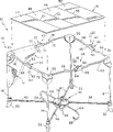
Fig. 1 is the perspective view that a Collapsible mobile is played.This playyard is according to the present invention includes a skeleton, a textile armature cover and in order to be installed in intraskeletal place pad;
Fig. 2 is the plan view from above of playyard among a Fig. 1, wherein a part of element is removed, and has shown the relation of following each parts: six support bars, and it and strut fixation device articulate, be positioned at pad below, place and supporting the place pad, this private school now is installed in the skeleton; Four upper rack posts, above support bar and surround a square formula, each upper rack posts comprises left and right pole section and a releasable pole section lock;
Fig. 3 is the side elevation view of playyard among a Fig. 2, demonstrates the relation with lower member: the bottom surface of strut fixation device is installed on a lifting position above the ground that is positioned under the pad of place with a base in order to support strut fixation.
Fig. 4 is the back elevation view of playyard among a Fig. 2 and Fig. 3;
Fig. 5 be one with Fig. 4 in the close view of playyard, this playyard is folded, the strut fixation device just spins off from some rotatable support bar, the just lifting (and support bar is rotated motion with respect to the strut fixation device) that makes progress of the ground under the playyard of strut fixation device, the pole section lock in four upper rack posts unclamps and allows left and right pole section relative motion in four upper rack posts to folding position then;
Fig. 6 is the plan view from above of playyard among a Fig. 2, the place pad of this playyard is removed, the skeleton of playyard is fully folded, the parts that this figure shows have the strut fixation device, six support bars with the pivot joint of strut fixation device, the rotatable control stick that a pair of lever lock releasable, that the diagonal angle is placed is moved, this lever lock is located in the strut fixation device of cover plate below, is between the lockable support bar of separating at two diagonal angles;
Fig. 7 is the side elevation view of playyard folding fully among Fig. 6;
Fig. 8 is the back elevation view of playyard folding fully among Fig. 6;
Fig. 9 is the decomposition diagram of strut fixation device among Fig. 1~Fig. 8, this figure shows: one in order to hold the pedestal of rotatable support bar, bar column spinner for each support bar use, the lever lock device of the lever operation formula of a lever lock that comprises a pair of slip and a pair of lock spring, one along a feathering axis and pedestal pivot joint, and the control stick that links to each other with the lever lock of each slip, the inner cover plate of strut fixation device and outer cover plate are in order to the plate fastener of fastening cover plate and strut fixation device; This figure also shows: extremity piece links to each other with each support bar, thereby extremity piece can not move relative to support bar, wherein, two fixedly extremity piece comprise the handle button that size just in time is connected with hammerlock in two lever locks, two support bars with this extremity piece can be locked on the strut fixation device like this, in case so that the playyard skeleton moves and become fully upright shape, just can stop these (and other) support bars to rotatablely move with respect to the strut fixation device;
Figure 10 be among Fig. 9 the strut fixation device its as shown in Figure 1 by fully the assembling after the amplification plan view from above;
Figure 11 is the cutaway view along Figure 10 section line 11-11, and this figure shows: two lever locks that the diagonal angle is separated, and extrude and be partial to by the lock spring to latched position, be connected with the handle button of the support bar extremity piece of two particular design; This figure also shows the control stick that is arranged on punctured position, and wherein, the cover plate of the outer end of control stick and strut fixation device is adjacent;
Figure 12 is the view similar to Figure 11, the manual operations of the lock construction of display pole control type, and the handle that makes the hammerlock of lever lock of slip not move from two support bars is smashed disengaging; Demonstration is along with lever lock and support bar handle button are separated, and support bar is around bar column spinner rotatablely moving with respect to the strut fixation device; Show that control stick rotates to the make progress position of projection of a cover plate that leaves the strut fixation device along counter-clockwise direction around feathering axis;
Figure 13 is the decomposition diagram of another embodiment of strut fixation device that is used for the playyard skeleton of Fig. 1~Fig. 8.This figure shows one in order to hold the pedestal of rotatable support bar, bar column spinner for each support bar use, the lock construction of the extruding control type of a lever lock that comprises a pair of slip and a pair of lock spring, a strut fixation device cover plate and be used for fastening cover plate and the plate fastener of strut fixation device; This figure shows that also extremity piece links to each other with each support bar, thereby extremity piece can not move relative to support bar, wherein, two fixedly extremity piece comprise the handle button that size just in time is connected with hammerlock in two lever locks, two support bars with this extremity piece can be locked on the strut fixation device like this, in case so that the playyard skeleton moves and become fully upright shape, just can stop these (and other) support bars to rotatablely move with respect to the strut fixation device;
Figure 14 be among Figure 13 the strut fixation device its with to amplification plan view from above after similar mode shown in Figure 1 is assembled fully;
Figure 15 is the cutaway view along the hatching 15-15 among Figure 14, and this figure shows that two are partial to latched position by lock spring roof pressure the lever locks of angular spacing, is connected with the handle button of the support bar extremity piece of two particular design;
Figure 16 is the view similar to Figure 15, shows the manual operations of the lock construction of extruding control type, makes the hammerlock of lever lock of slip smash disengaging from the fixing handle of two support bars; Demonstration is along with lever lock and support bar handle button are separated, and support bar is around bar column spinner rotatablely moving with respect to the strut fixation device;
Figure 17 be to Figure 11 in the view of another embodiment of similar releasable lever lock device, this figure shows can make the lever lock of two spring deflections move relative to each other to the pull-type acting device of support bar disengaging configuration, it comprises a pair of driving element and coupled belt, the upper end that each driving element has a lower end that is articulated with the strut fixation device and extends into the finger accommodating chamber and link to each other with belt;
Figure 18 is the plan view from above as a part of device of Figure 17 demonstration, shows the upper end of belt and each driving element of the finger accommodating chamber that is arranged in one of lever lock;
Figure 19 is the view similar to Figure 17, shows a manual part that upwards lifts belt, makes two driving elements with respect to the rotation of strut fixation device, thereby makes two lever locks be contracted to the support bar disengaging configuration;
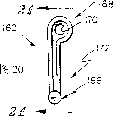
Figure 20 is the amplification side elevation view as the driving element of Figure 17~shown in Figure 19;
Figure 21 is the cutaway view along the hatching 21-21 of Figure 20, shows a T type pedestal and a tip that links to each other with band of this driving element;
Figure 22 is the view similar to Figure 17, shows another embodiment of releasable lever lock device, and wherein two lever locks are partial to the support bar latched position by roof pressure;
Figure 23 is the view similar to Figure 22, shows a manual part that upwards lifts belt, makes two driving element rotations, thereby makes two lever locks be contracted to the support bar disengaging configuration.
The specific embodiment
Playyard 10 comprises that collapsible skeleton 12, one textile armature covers 14 and can remove place pad 16.Skeleton cover 14 is made by solid fabric and reticular substance, thereby and can fold and can make that skeleton 12 is easy to become collapsed shape shown in Fig. 6~8 from the upright shape shown in Fig. 1~4.Place pad 16 was removed from skeleton 12 (as shown in Figure 1) before folding frame 12.In case skeleton 12 is folded, quadruple place pad 16 also can be folded also " parcel " around folding skeleton 12, and fixing with belt (not painting), is used to store and/or transport folding skeleton 12 so that one " chest " to be provided.
Each support bar 36,38,40 and 42 has the outer end and the inner that is articulated with strut fixation device 32 that are articulated with one of limit base 22, so that the folding movement of skeleton 12 from the upright shape shown in Fig. 1~4 to the collapsed shape shown in Fig. 6~8.Each auxiliary support bar 44 and 46 has the inner and the outer end that are articulated with strut fixation device 32, and this outer end is formed into, for instance, and bar base for supporting 56 as shown in Figure 1 and Figure 4.In case assembling, support bar 36,38,40 and 42 is just arranged in a kind of mode of X-shaped shape, and auxiliary support bar 44 is aligned to five equilibrium by support bar 36 and 38 angles that surrounded, and auxiliary support bar 46 is aligned to five equilibrium by support bar 40 and 42 angles that surrounded.
Preceding upper rack posts 24 comprises a left branching rod section 58 that is articulated with one of limit piece 20, a right pole section 60, it is connected to do with respect to left branching rod section 58 (for instance, in following mode) and the rotatablely moving of adjacent limit piece 20, and a releasable pole section lock 62, made with being mounted to left branching rod section 58 and right pole section 60 " lock " are in the same place the relation of the mutual polyphone shown in becoming, for example, as skeleton 12 to shown in Fig. 1~3 of its upright shape motion.In a dissection type lock shell 63, this lock shell 63 has one not to be connected with right pole section 60 is crooked with one with the not crooked left part that is connected 64 of left branching rod section 58 to releasable pole section lock 62 by device, and the right part 65 that is articulated with left part 64.Left branching rod section 58 and left part 64 is one-body molded and right pole section 60 and right part 65 is one-body molded, also within the scope that the present invention discloses.
Each right side upper rack posts 26, rami posterior superior bar 28 and left side upper rack posts 30 are structurally all close with preceding upper rack posts 24, and promptly each pole all comprises a dissection type lock shell 63 that contains a releasable pole section lock 62.Right side upper rack posts 26 comprise one be articulated with one of limit piece 20 and be articulated with adjacent edge piece 20 with one with the not crooked left branching rod section 66 that is connected of left part 64 of second lock shell 63 and with the not crooked right pole section 68 that is connected of right part 65 of second lock housing 63, rami posterior superior bar 28 comprise one be articulated with one of limit piece 20 and be articulated with adjacent edge piece 20 with one with the 3rd the not crooked left branching rod section 70 that is connected of left part 64 of locking shell 63 and with the 3rd the not crooked right pole section 72 that is connected of right part 65 of locking shell 63.Left side upper rack posts 30 comprise one be articulated with one of limit piece 20 and be articulated with adjacent edge piece 20 with one with the not crooked left branching rod section 74 that is connected of left part 64 of the 4th lock shell 63 and with the 4th the not crooked right pole section 76 that is connected of right part 65 of locking shell 63.
A releasable lever lock device 78 is contained in the strut fixation device 32, and the latter end that does not move that will be fixed on some support bar 36,38,40,42 the inner when proper skeleton 12 is set for as shown in Figure 1 upright shape is locked on the strut fixation device 32.In the embodiment that this illustrates, lever lock device 78 is made into to be connected with the fixedly latter end that is fixed on each support bar 36,40 the inner, can stop during for as shown in Figure 1 upright shape support bar 36,40 with respect to the rotatablely moving of strut fixation device 32 when skeleton 12 thus, thereby can prevent that skeleton 12 from carrying out folding movement to its collapsed shape.Lever lock device 78 is made into releasable, so that the user is after removing place pad 16 and exposing strut fixation device 32, expert's wage adjustment pole locking device 78 and remove the locking relation be based upon between strut fixation device 32 and the support bar 36,40, can allow the support bar 36,40 of present non-locking to be rotated motion thus with respect to strut fixation device 32, for instance, control the situation of skeleton 12 folding processes as shown in Figure 5.
Now consult Fig. 1 and Fig. 5, by removing place pad 16, the releasable lever lock device 78 of manual adjustment, then strut fixation device 32 54 is lifted partly folding support bar 36,38,40,42,44,46 from ground, then each of these four releasable pole section locks 62 of manual adjustment is come partly folding upper rack posts 24,26,28,30, thereby playyard 10 can be folded.Then, skeleton 12 can further be folded into a folding fully shape, for instance, and as Fig. 6~shown in Figure 8.At last, if necessary, place pad 16 can be wrapped in around the folding skeleton 12, and by using suitable method to fix, thinks that folding skeleton 12 provides a storage bin or transport case.
Fig. 9 to Figure 12 has shown an embodiment of strut fixation device 32 and releasable lever lock 78.As shown in Figure 9, strut fixation device 32 comprises a pedestal 80, an inner cover plate 82, an outer cover plate 282 and six plate fasteners 84, releasable lever lock device 78 comprises two movably 86,88 and two springs 90,92 of lever lock, this two spring is used to promote lever lock 86,88 and carries out the opposite direction motion in strut fixation device 32, is connected and lock support bar 36,40, thereby stops its motion with respect to strut fixation device 32.A single cover plate is provided, and wherein inner cover plate 82 lumps together with outer cover plate 282, and this is also within the disclosed scope of the present invention.
In the embodiment of Fig. 9~12, a control stick 210 rotatably installs in strut fixation device 32, and can be around a feathering axis 249 motions, this control stick can be arranged to make lever lock 86,88 to move in opposite directions mutually relative to spring 90,92, thereby lever lock 86,88 from connecting, is freed in the locking of the inner (for example, Gu Ding latter end 134) of itself and support bar 36,40.In the embodiment of Figure 13~Figure 16, control stick 210 has been removed, the lever lock similar to lever lock 86,88 be configured to and settle can be by operator's clipping, and " by pinching " (" squeeze actuated ") and make those lever locks from its locking with support bar 36,40 is connected, free.Figure 17~23 have shown other embodiment of lever lock device.
Each interior wall 116 comprises a post holding tank 118 that can hold a bar column spinner 120 1 ends therein.The function of bar column spinner 120 is the inner of each support bar 36,38,40,42,44,46 and strut fixation device 32 are coupled together, and carries out rotatablely moving with respect to strut fixation device 32.Each support bar 36,38,40,42,44,46 comprises hole 122 or other suitable post jacks of fixed leg.
The size of outer cover plate 282 and shape can be covered on the inner cover plate 82 as Fig. 9~shown in Figure 12.Outer cover plate 282 is made into to comprise a cross-hole 285, in order to hold a part of control stick 210 and swingle 212 therein.Hole 285 can be designed to form a groove, when control stick 210 rotates to punctured position around feathering axis 249, in order to the outside (handle) 245 that holds control stick 210 therein.
One lockable fixedly extremity piece 134 links to each other with the inner of each support bar 36,40, so that its corresponding support bar 36 or 40 motions relatively.Lockable fixedly extremity piece 134 be configured to comprise one with support bar 36,40 one of them footstalk that are connected 136, a head 138 and a handle button 140 (armcatch) that is attached on the head 138 that is attached on the footstalk 136, this handle are buckled in when skeleton 12 is moved into to upright shape can one of them links to each other with lever lock 86,88 in being arranged on strut fixation device 32.The stiff end 142 of a head on comprising a footstalk and being attached to footstalk and each support bar 38,42,44 link to each other with the inner of 46.
Each lever lock 86,88 comprises a lock body 150, a pair of lead arm (as flat) 152 and one hammerlock 154 that is attached to lock body 150 bottom surfaces and is parallel to each other the separation setting.Each lever lock 86,88 in Figure 13~Figure 16 embodiment comprises that also a user connects hole 133 enterable finger accommodating chambers 155 by being arranged in the cover plate 82, as shown in figure 16.In case hammerlock 154 is configured to skeleton 12 and is moved into upright shape, just be connected (as locking) with the handle button 140 that is located at respective support bar one end 36,40.Each lever lock 86,88 more comprises a pair of balancing pole 156 that is attached to the separation of lock body 150 relative both sides, and this balancing pole 156 supports and the end that is being connected spring 90,92.
In the embodiment of Fig. 9~Figure 12, each lever lock 86,88 more comprises a bar 237 that links to each other with bar fixture 239 on the lock body 150 that is attached to lever lock 86 or 88.As Figure 10~shown in Figure 12, each bar 237 will match with the groove 241 in being arranged on control stick 210 inner 243.Groove 241 with respect to the position composition of the swingle 212 in the middle of two grooves every relation, as Figure 11 and shown in Figure 12.Swingle 212 matches with the hole 213 that is arranged on control stick 210 the inners 243 as shown in Figure 9, and by device in strut fixation device 32 to produce a feathering axis 249.
Showing that as among Figure 11 and Figure 12 lever lock 86,88 transfers the action of unclamping support bar 36,40 to from locking mutually to be connected with strut fixation device 32.Shown in Figure 11 (and Figure 15), spring 90,92 is lever lock 86,88 roof pressure round about, makes hammerlock 154 be connected with lockable extremity piece 134 on being connected support bar 36,40.In order to unclamp handling as Fig. 9~shown in Figure 12 at lever-type, lever lock 86,88 in the releasable lever lock device 78, control stick 210 is handled by a user, make lever lock 86,88 move relative to each other around swingle 212 with counter-clockwise direction 214 (as shown in figure 12) rotation, thereby hammerlock 154 is broken away from from fixing handle button 140 towards spring 90,92.In order to unclamp handling as Figure 13~shown in Figure 16 at squash type, lever lock 86,88 in the releasable lever lock device 78, the user stretches into two fingers in the finger accommodating chamber 155 that is located in the lock body 150, finger is moved relative to each other with direction 158,160 (as shown in figure 16), and " extruding " spring 90,92 makes hammerlock 154 buckle 140 disengagings from handle.Strut fixation device 32 can be got up from 54 liftings of following ground then, begins collapsible skeleton 12 with a kind of, and for instance, above-mentioned mode folds.
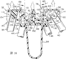
Another embodiment of strut fixation device and releasable lever lock shows in Figure 17~19, as shown in figure 17, the a pair of driving element (drive member) 162,164 with strut fixation device 32 ' link to each other of releasable lever lock 78 ' comprise, this driving element is installed to such an extent that can move with respect to the strut fixation device by a belt 165 (or other anchor clamps), make lever lock 86 ', 88 ' tighten and break away from the lockable end 134 of support bar 36,40.
In the embodiment shown, the lower end of each driving element 162,164 166 and base 34 ' a part be articulated, can be around axle 167 motions; The upper end of each driving element 162,164 be placed in lever lock 86 ', 88 ' one of them of finger accommodating chamber 155 within.Selectively, lower end 166 can be articulated with strut fixation device pedestal 80.Upper end 168 comprises a hole 170 (or other appropriate device) in order to connect a part of belt 165.The stage casing 172 of each driving element 162,164 from be arranged on lever lock 86 ', 88 ' opening 174 and be arranged on strut fixation device 32 ' base plate 146 ' opening 176 in pass.As Figure 13 and shown in Figure 14, belt 165 passes to be arranged on and connects hole 133 in the cover plate 82, thereby exposes strut fixation device 32 in case place pad 16 is removed from playyard 10, and then the band part 178 of belt 165 can be user's gained.
During use, the user catches belt 165 upwards to lift at band 178 positions, as shown in figure 19.The action that acts on belt 165 makes driving element 162,164 around rotating shaft 167 rotations, connect so that the upper end 168 of driving element 162,164 moves relative to each other lever lock 86 ', 88 ', and make lever lock 86 ', 88 ' move relative to each other to the position that pole is broken away from, the 166 one-tenth T types in the lower end of each driving element 162,164, and form column spinner 180,181.
Also have, another embodiment of strut fixation device and releasable lever lock shows in Figure 22 and Figure 23.In this embodiment, cover plate 82 ' comprise having only single band accommodation hole 133 ', rather than two shown in the embodiment connect hole 133 in the past.Hole 133 ' link to each other with the upper end 168 of driving element 162,164 is passed in the end of belt 165, and the hole 133 of cover plate 82 ' interior ' above and the outside band 178 that leaves belt 165.
Though the present invention is described in detail by some most preferred embodiment, various modifications and changes are still within the scope and spirit of the present invention described in the following claim.
Claims (26)
1, a kind of playyard place support frame is characterized in that, comprising:
A strut fixation device;
At least two place support bars, each place support bar comprises a inner that is articulated with this strut fixation device, each place support bar can be moved around the relative strut fixation device of a bar rotating shaft between a upright shape and a collapsed shape, this upright shape can be in order to supporting the place pad on place support bar and the strut fixation device, the storage that this collapsed shape can convenient place support frame; With
A lever lock device that links to each other with this strut fixation device, this lever lock device comprises that is arranged on a movably lever lock of strut fixation device, and this lever lock is configured to put fixedly extremity piece locking mutually on the inner of selected place support bar with device, and stop selected place support bar to be rotated motion around the relative strut fixation device of rotating shaft, when thereby support bar moves to upright shape with respect to the strut fixation device then and there, just selected place support bar is locked on the strut fixation device.
2, skeleton according to claim 1, it is characterized in that: this strut fixation device comprises a pedestal, this lever lock device comprises two lever locks that are arranged in the pedestal, in order between link position and released position, to move, when link position, the place support bar that lever lock connects and locking is selected, thus prevent to form a kind of upright shape with respect to base motion; When the released position, lever lock breaks away from selected support bar, allows selected place support bar to rotatablely move to collapsed shape around this bar rotating shaft.
3, skeleton according to claim 2 is characterized in that: this lever lock device more comprises to be used so that each lever lock is partial to the device to link position.
4, skeleton according to claim 2, it is characterized in that: this lever lock device comprises that more one articulates with pedestal, in order to the control stick that between locking and disengaging configuration, moves around a feathering axis, this control stick links to each other with two lever locks, and be provided with to such an extent that can make two lever locks move to the released position mutually, with feathering axis the rotatablely moving with respect to pedestal of response control stick around control stick.
5, skeleton according to claim 4 is characterized in that: this lever lock device more comprises to be used so that each lever lock is partial to the device to link position.
6, skeleton according to claim 4, it is characterized in that: this lever lock device comprises that more one is located on the pedestal, and settle to such an extent that cover two cover plates on the lever lock, this control stick comprises that a feathering axis and a pedestal around control stick articulates, and the inner that links to each other with each lever lock slip and the movably outer end of feathering axis from punctured position to the projection position around control stick, this constriction device is adjacent with cover plate when two lever locks are moved into latched position, and separate with cover plate when two lever locks are moved into disengaging configuration this projection position.
7, skeleton according to claim 4 is characterized in that: this control stick comprises first groove and second groove, and the feathering axis of control stick is arranged between two grooves; First lever lock comprises one first lock body, one first hammerlock, this first hammerlock links to each other with this first lock body, and be provided with when lever lock moves to latched position just with chosen place support bar in one of the inner link to each other first bar that links to each other with first lock body and stretch in first groove that is located in the control stick; Second lever lock comprises one second lock body, one second hammerlock, this second hammerlock links to each other with second lock body and is provided with to such an extent that just linking to each other with the inner in another chosen place support bar when lever lock moves to latched position, second bar that links to each other with this second lock body and stretch in second groove that is located in the control stick.
8, playyard according to claim 1 place support frame is characterized in that: this lever lock device more comprises with so that lever lock is partial to the device to link position.
9, playyard according to claim 8 place support frame is characterized in that: this usefulness so that lever lock be partial to the device of link position be a kind of compression spring.
10, playyard according to claim 1 place support frame, it is characterized in that: this lever lock device comprises that more one articulates with the strut fixation device, in order to the control stick that between locking and disengaging configuration, moves around a feathering axis, this control stick links to each other with strut fixation device slip, so that lever lock moves to a position of unclamping with respect to the strut fixation device, thereby this selected place support bar is broken away from from the strut fixation device.
11, playyard according to claim 1 place support frame, it is characterized in that: this strut fixation device comprises a pedestal and at least one bar column spinner, wherein a bar column spinner links to each other with pedestal the inner with the place support bar of selecting, thereby produce described bar rotating shaft, and fixedly extremity piece comprises a footstalk that links to each other with the inner of the place support bar of selecting, a head and the handle button that is attached on this head that is attached on this footstalk, this handle button bit and just connects into locking relation with lever lock when this selected place support bar moves to upright shape between a lever lock and a described bar column spinner.
12, playyard according to claim 11 place support frame, it is characterized in that: this pedestal comprises a bar holding tank, the inner of place support bar that should be selected is positioned at this bar holding tank, this lever lock comprise one be arranged in this bar holding tank can before and after the lock body and a hammerlock that links to each other with this lock body of slippage, and this hammerlock when this place support bar of selecting moves to upright shape just with this pole holding tank in handle link and connect.
13, playyard according to claim 12 place support frame, it is characterized in that: a described bar column spinner is horizontally through the bar holding tank.
14, playyard according to claim 13 place support frame, it is characterized in that: this pedestal comprises a pair of inwall that is apart from one another by relation, thereby formed this bar holding tank betwixt, each inwall comprises a post holding tank that holds an end of a described bar column spinner within it.
15, a kind of playyard place support frame comprises
Four limit bases,
A strut fixation device,
Four place support bars, each place support bar comprise one with the limit base in one of the outer end that is articulated and the inner that is articulated with the strut fixation device, make the place support bar between upright shape and collapsed shape, can carry out folding movement; In upright shape, the place support bar is configured to * style of type, in order to support on it with the strut fixation device on the place pad; In collapsed shape, the place support bar is configured to the storage that is beneficial to the place support frame parallel to each other; With
One is arranged in the strut fixation device and coupled lever lock device, fixedly extremity piece on this lever lock device and the inner that is arranged at least one place support bar is snap close mutually, and prevent at least one place support bar, thereby just at least one place support bar is locked on the strut fixation device when support bar moves to upright shape with respect to the strut fixation device then and there with respect to the rotatablely moving of strut fixation device.
16, skeleton according to claim 15, it is characterized in that: this strut fixation device comprises a pedestal, this lever lock device comprises two lever locks that are arranged in this pedestal, in order between link position and released position, to move, when link position, lever lock connects and locks at least one place support bar, prevents with respect to base motion, thereby forms a kind of upright shape; When the released position, lever lock breaks away from selected support bar, allows at least one place support bar to rotatablely move to collapsed shape around rotating shaft.
17, skeleton according to claim 16 is characterized in that: this lever lock device more comprises to be used so that each lever lock is partial to the device to link position.
18, skeleton according to claim 16, it is characterized in that: this lever lock device comprises that more one articulates with pedestal, in order to the control stick that between locking and disengaging configuration, moves around a feathering axis, this control stick links to each other with two lever locks, and be provided with to such an extent that can make two lever locks move to the released position each other, with feathering axis the rotatablely moving with respect to pedestal of response control stick around control stick.
19, skeleton according to claim 18 is characterized in that: this lever lock device more comprises to be used so that each lever lock is partial to the device to link position.
20, skeleton according to claim 15, it is characterized in that: this strut fixation device comprises a pedestal, this lever lock device comprises a lever lock that is arranged in this pedestal, in order between link position and released position, to move, when link position, lever lock connect and locking place support bar in one of the inner, prevent with respect to base motion, thereby form a kind of upright shape; When the released position, lever lock breaks away from the inner of one of this place support bar, allows the place support bar to rotatablely move to collapsed shape.
21, skeleton according to claim 20 is characterized in that: this lever lock device more comprises to be used so that each lever lock is partial to the device to link position.
22, a kind of playyard place support frame is characterized in that, comprising:
A strut fixation device that comprises a pedestal and coupled bar column spinner,
At least two place support bars, each place support bar comprises a inner that is articulated with one of bar column spinner of this strut fixation device, each place support bar can be moved around relative this strut fixation device of a bar rotating shaft between upright shape and collapsed shape, this upright shape can be in order to supporting the place pad on place support bar and the strut fixation device, the storage that this collapsed shape can this place support frame of facility; With
A lever lock device that links to each other with this strut fixation device, it is configured to and the fixedly handle button locking mutually of extremity piece of installing on selected support bar the inner, place, and stop this selected place support bar to be rotated motion around this bar rotating shaft with respect to this strut fixation device, thereby the place support bar that just will select when this place support bar moves to upright shape with respect to this strut fixation device is locked on this strut fixation device; Each handle button is located between this lever lock device and one of them the bar column spinner when this selected place support bar moves to upright shape.
23, playyard support frame according to claim 22, it is characterized in that: each fixedly extremity piece comprise that more a footstalk and that links to each other with the inner of this selected place support bar is attached to the head on this footstalk, each handle button one of is attached in the head, between lever lock and bar column spinner, and when moving to upright shape, this selected place support bar just becomes locking relation with the lever lock device.
24, playyard support frame according to claim 23, it is characterized in that: this pedestal comprises the bar holding tank, the inner of the place support bar that each is selected is positioned at one of them bar holding tank, this lever lock device comprise one be arranged in each bar holding tank can before and after the lock body and a hammerlock that links to each other with each lock body of slippage, and this hammerlock and this handle button are connected in the corresponding bar holding tank.
25, playyard support frame according to claim 24 is characterized in that: each bar column spinner is horizontally through one of them bar holding tank.
26, playyard support frame according to claim 25, it is characterized in that: this pedestal comprises a pair of inwall that is apart from one another by relation, thereby formed this bar holding tank betwixt, each inwall comprises a post holding tank that holds an end of a described bar column spinner within it.
Applications Claiming Priority (2)
| Application Number | Priority Date | Filing Date | Title |
|---|---|---|---|
| US5937697P | 1997-09-19 | 1997-09-19 | |
| US60/059,376 | 1997-09-19 |
Publications (2)
| Publication Number | Publication Date |
|---|---|
| CN1278706A CN1278706A (en) | 2001-01-03 |
| CN1127931C true CN1127931C (en) | 2003-11-19 |
Family
ID=22022564
Family Applications (1)
| Application Number | Title | Priority Date | Filing Date |
|---|---|---|---|
| CN98811196.9A Expired - Fee Related CN1127931C (en) | 1997-09-19 | 1998-09-18 | Playyard |
Country Status (7)
| Country | Link |
|---|---|
| US (1) | US6256814B1 (en) |
| EP (1) | EP1022970B1 (en) |
| CN (1) | CN1127931C (en) |
| CA (1) | CA2303867C (en) |
| DE (1) | DE69820097T2 (en) |
| TW (1) | TW367233B (en) |
| WO (1) | WO1999015052A1 (en) |
Families Citing this family (41)
| Publication number | Priority date | Publication date | Assignee | Title |
|---|---|---|---|---|
| EP1199011B1 (en) * | 2000-08-14 | 2002-10-16 | Shu-Yu Kuo | Bottom frame structure for playpen |
| US6510569B1 (en) * | 2000-11-20 | 2003-01-28 | Stephen Hu | Double locks for the chassis of game-bed |
| US6510570B2 (en) * | 2001-05-08 | 2003-01-28 | Graco Children's Products Inc. | Playard having corner panels |
| US6698042B2 (en) * | 2001-05-18 | 2004-03-02 | Pao-Hsien Cheng | Base of a foldable baby bed |
| US6568004B1 (en) * | 2002-01-24 | 2003-05-27 | Dongguan Crown Shin Baby Appliances Co. Ltd. | Retraction control device for baby joyful bed |
| CN2585598Y (en) * | 2002-09-10 | 2003-11-12 | 明生投资公司 | Base self-lock structure of baby's bed |
| US6615424B1 (en) * | 2002-11-21 | 2003-09-09 | Pao-Hsien Cheng | Base of a foldable baby bed |
| US6665895B1 (en) * | 2002-12-20 | 2003-12-23 | Cosco Management, Inc. | Playyard floor lock system |
| US6865756B2 (en) * | 2003-05-28 | 2005-03-15 | Graco Children's Products Inc. | Playard |
| US20060021137A1 (en) * | 2004-07-30 | 2006-02-02 | Simplicity, Inc. | Collapsible play yard |
| US20060021138A1 (en) * | 2004-07-30 | 2006-02-02 | Simplicity, Inc. | Collapsible play yard |
| USD534381S1 (en) | 2004-11-05 | 2007-01-02 | Kolcraft Enterprises, Inc. | Exposed legs for a play yard |
| TWM271497U (en) * | 2005-01-21 | 2005-08-01 | Link Treasure Ltd | Collapsible chassis structure of infant and child playing bed |
| US7568242B2 (en) * | 2005-02-23 | 2009-08-04 | Kolcraft Enterprises | Play yards and methods of operating the same |
| US20060225204A1 (en) * | 2005-04-08 | 2006-10-12 | Ted Bretschger | Rockable sleeping compartments attachable to play yards and methods of operating the same |
| US7458114B2 (en) * | 2005-04-08 | 2008-12-02 | Kolcraft Enterprises, Inc. | Clips for mounting accessories to play yards and methods of operating the same |
| US20070017025A1 (en) * | 2005-07-22 | 2007-01-25 | Baby Trend, Inc. | Folding play yard |
| CN101291911B (en) | 2005-10-19 | 2014-08-13 | 泰华制药工业有限公司 | Crystals of laquinimod sodium, and process for the manufacture thereof |
| TWM297204U (en) * | 2006-03-02 | 2006-09-11 | Link Treasure Ltd | Collapsible playyard base frame |
| US20080127412A1 (en) * | 2006-11-30 | 2008-06-05 | Brian Pleiman | Portable infant playyard |
| US7661156B2 (en) * | 2007-02-15 | 2010-02-16 | Thorley Industries, Llc | Portable folding play yard with stabilized corner posts |
| CN101674759B (en) | 2007-02-14 | 2013-11-20 | 索利产业公司 | Foldable child enclosure |
| US8141186B2 (en) | 2007-09-25 | 2012-03-27 | Kids Ii, Inc. | Mesh arrangement for bassinet assembly |
| GB2455116A (en) * | 2007-11-29 | 2009-06-03 | Pao-Hsien Cheng | Base structure of a baby mesh bed |
| CN101496689B (en) * | 2008-02-01 | 2011-04-20 | 程宝贤 | Security locking structure of baby's game bed foundation |
| CN201393790Y (en) * | 2008-04-18 | 2010-02-03 | 宝钜实业股份有限公司 | Baby crib base mechanism |
| US8407832B2 (en) * | 2008-10-30 | 2013-04-02 | Mattel, Inc. | Infant support structure with a collapsible frame |
| CN101856183B (en) * | 2009-04-08 | 2013-11-27 | 宝钜(中国)儿童用品有限公司 | Baby crib base mechanism and baby crib employing same |
| US9149128B2 (en) | 2011-02-24 | 2015-10-06 | Kids Ii, Inc. | Play yard with removable liner |
| US8650678B2 (en) | 2011-03-28 | 2014-02-18 | Thorley Industries Llc | Corner latching play yard |
| CN102979811A (en) | 2011-09-07 | 2013-03-20 | 儿童二代公司 | A hinge mechanism for a game bed frame |
| US8973181B2 (en) | 2012-04-20 | 2015-03-10 | Thorley Industries Llc | Wheel assembly for a foldable child enclosure |
| US9351588B2 (en) | 2012-11-29 | 2016-05-31 | Kids Ii, Inc. | Child support unit for a play yard |
| WO2014153145A2 (en) | 2013-03-14 | 2014-09-25 | Teva Pharmaceutical Industries Ltd. | Crystals of laquinimod sodium and improved process for the manufacture thereof |
| TWM466587U (en) * | 2013-06-13 | 2013-12-01 | Delsun Co Ltd | Game bed |
| CA2971283A1 (en) * | 2014-09-19 | 2016-03-24 | Nicolas Brun | Foldable bed |
| CN104367042B (en) * | 2014-11-17 | 2017-02-22 | 好孩子儿童用品有限公司 | Game enclosing frame |
| CN104398071B (en) * | 2014-12-04 | 2016-08-24 | 茅鸿勇 | For folding the footing device of play yard |
| US11363893B2 (en) | 2018-11-08 | 2022-06-21 | Henry F. Thorne | Foldable play yard |
| US11589686B2 (en) | 2019-06-17 | 2023-02-28 | Henry F. Thorne | Unfolding play yard |
| US11589685B2 (en) | 2020-04-29 | 2023-02-28 | Monahan Products, LLC | Play yard |
Family Cites Families (14)
| Publication number | Priority date | Publication date | Assignee | Title |
|---|---|---|---|---|
| US4739527A (en) * | 1986-07-08 | 1988-04-26 | Sassy, Inc. | Portable foldable playpen |
| US4688280A (en) * | 1986-10-20 | 1987-08-25 | Kohusmariol, Inc. | Foldable playpen assembly with ease of portability |
| US4811437A (en) * | 1987-06-26 | 1989-03-14 | Graco Metal Products, Inc. | Foldable playyard |
| US5339470A (en) * | 1992-04-14 | 1994-08-23 | Louis Shamie | Combination foldable playpen and dressing/changing table |
| US5239714A (en) * | 1992-08-12 | 1993-08-31 | Huang Ming T | Playpen structure |
| US5279006A (en) * | 1992-08-28 | 1994-01-18 | Teng Jerry M S | Play yards for infants |
| US5358220A (en) * | 1993-03-16 | 1994-10-25 | Yu Kuang Hsiung | Playpen frame structure |
| US5353451A (en) * | 1993-06-03 | 1994-10-11 | Hsiung Yu Kuang | Playpen frame structure |
| DE19519119B4 (en) * | 1994-11-04 | 2007-03-15 | Graco Children's Products, Inc. | Foldable playpen and hub for it |
| US5465439A (en) * | 1994-12-08 | 1995-11-14 | Jina Manufacturer Thai Co., Ltd. | Device for retaining a playpen in an extended position |
| US5504951A (en) * | 1995-01-23 | 1996-04-09 | Yeh; Chin C. | Foldable baby playyard |
| US5699997A (en) * | 1996-04-22 | 1997-12-23 | Huang; Li-Chu Chen | Foldable playyard connection device |
| US5819342A (en) * | 1997-02-05 | 1998-10-13 | Graco Children's Products Inc. | Foldable playyard with latch locking hub system |
| US5937457A (en) * | 1998-09-18 | 1999-08-17 | Li-Ju Chen | Cradle base collapsible mechanism |
-
1998
- 1998-09-18 CN CN98811196.9A patent/CN1127931C/en not_active Expired - Fee Related
- 1998-09-18 CA CA002303867A patent/CA2303867C/en not_active Expired - Fee Related
- 1998-09-18 US US09/508,946 patent/US6256814B1/en not_active Expired - Lifetime
- 1998-09-18 WO PCT/US1998/019456 patent/WO1999015052A1/en active IP Right Grant
- 1998-09-18 EP EP98953172A patent/EP1022970B1/en not_active Expired - Lifetime
- 1998-09-18 DE DE69820097T patent/DE69820097T2/en not_active Expired - Fee Related
- 1998-11-06 TW TW087115646A patent/TW367233B/en active
Also Published As
| Publication number | Publication date |
|---|---|
| EP1022970B1 (en) | 2003-11-26 |
| WO1999015052A1 (en) | 1999-04-01 |
| DE69820097D1 (en) | 2004-01-08 |
| CN1278706A (en) | 2001-01-03 |
| EP1022970A4 (en) | 2001-01-31 |
| CA2303867C (en) | 2004-05-11 |
| CA2303867A1 (en) | 1999-04-01 |
| DE69820097T2 (en) | 2004-09-02 |
| US6256814B1 (en) | 2001-07-10 |
| EP1022970A1 (en) | 2000-08-02 |
| TW367233B (en) | 1999-08-21 |
Similar Documents
| Publication | Publication Date | Title |
|---|---|---|
| CN1127931C (en) | Playyard | |
| US6350221B1 (en) | Convertible exercise apparatus with body supporting element | |
| CN100506106C (en) | Bag with caster wheels | |
| CN1085185C (en) | Folding stage system | |
| US4645196A (en) | Folding weight bench | |
| CN1316577A (en) | Folding tent support | |
| DE102008054185A1 (en) | Play stalls with motorized cradle | |
| CN103517655A (en) | Corner latching play yard | |
| CN2271317Y (en) | Retrieving and expanding device for wheel group of baby's rocking chair | |
| CN108294553A (en) | Travelling cradle for infant | |
| CN115040848A (en) | Basketball playing device | |
| CN207950541U (en) | A kind of national dance training device | |
| CN1299689A (en) | Golf-bag cart | |
| CN111035185A (en) | Game bed | |
| CN201723935U (en) | Mortised joint bracket | |
| CN2314834Y (en) | Convertible two purpose table | |
| CN112641231A (en) | Portable dining table | |
| CN1902075A (en) | Hand carrier | |
| CN2751639Y (en) | Supporting frame for hammock | |
| TW202412679A (en) | Bassinet accessory for a foldable playard | |
| CN2852819Y (en) | Open-close type handicraft tuble with built in table top | |
| CN220301906U (en) | Tent convenient to extend and fold | |
| CN212995242U (en) | Base structure of electric mahjong table and electric mahjong table | |
| CN212233862U (en) | Game bed | |
| CN2226406Y (en) | Combined multipurpose table |
Legal Events
| Date | Code | Title | Description |
|---|---|---|---|
| C06 | Publication | ||
| PB01 | Publication | ||
| C10 | Entry into substantive examination | ||
| SE01 | Entry into force of request for substantive examination | ||
| C14 | Grant of patent or utility model | ||
| GR01 | Patent grant | ||
| C19 | Lapse of patent right due to non-payment of the annual fee | ||
| CF01 | Termination of patent right due to non-payment of annual fee |