CN1127880C - Improvements in downlink observed time difference measurements - Google Patents
Improvements in downlink observed time difference measurements Download PDFInfo
- Publication number
- CN1127880C CN1127880C CN 99811740 CN99811740A CN1127880C CN 1127880 C CN1127880 C CN 1127880C CN 99811740 CN99811740 CN 99811740 CN 99811740 A CN99811740 A CN 99811740A CN 1127880 C CN1127880 C CN 1127880C
- Authority
- CN
- China
- Prior art keywords
- radio signal
- information
- time
- mobile service
- service station
- Prior art date
- Legal status (The legal status is an assumption and is not a legal conclusion. Google has not performed a legal analysis and makes no representation as to the accuracy of the status listed.)
- Expired - Lifetime
Links
Images


Classifications
-
- H—ELECTRICITY
- H04—ELECTRIC COMMUNICATION TECHNIQUE
- H04W—WIRELESS COMMUNICATION NETWORKS
- H04W64/00—Locating users or terminals or network equipment for network management purposes, e.g. mobility management
-
- G—PHYSICS
- G01—MEASURING; TESTING
- G01S—RADIO DIRECTION-FINDING; RADIO NAVIGATION; DETERMINING DISTANCE OR VELOCITY BY USE OF RADIO WAVES; LOCATING OR PRESENCE-DETECTING BY USE OF THE REFLECTION OR RERADIATION OF RADIO WAVES; ANALOGOUS ARRANGEMENTS USING OTHER WAVES
- G01S1/00—Beacons or beacon systems transmitting signals having a characteristic or characteristics capable of being detected by non-directional receivers and defining directions, positions, or position lines fixed relatively to the beacon transmitters; Receivers co-operating therewith
- G01S1/02—Beacons or beacon systems transmitting signals having a characteristic or characteristics capable of being detected by non-directional receivers and defining directions, positions, or position lines fixed relatively to the beacon transmitters; Receivers co-operating therewith using radio waves
- G01S1/022—Means for monitoring or calibrating
- G01S1/026—Means for monitoring or calibrating of associated receivers
-
- G—PHYSICS
- G01—MEASURING; TESTING
- G01S—RADIO DIRECTION-FINDING; RADIO NAVIGATION; DETERMINING DISTANCE OR VELOCITY BY USE OF RADIO WAVES; LOCATING OR PRESENCE-DETECTING BY USE OF THE REFLECTION OR RERADIATION OF RADIO WAVES; ANALOGOUS ARRANGEMENTS USING OTHER WAVES
- G01S5/00—Position-fixing by co-ordinating two or more direction or position line determinations; Position-fixing by co-ordinating two or more distance determinations
- G01S5/02—Position-fixing by co-ordinating two or more direction or position line determinations; Position-fixing by co-ordinating two or more distance determinations using radio waves
- G01S5/10—Position of receiver fixed by co-ordinating a plurality of position lines defined by path-difference measurements, e.g. omega or decca systems
Landscapes
- Engineering & Computer Science (AREA)
- Computer Networks & Wireless Communication (AREA)
- Physics & Mathematics (AREA)
- General Physics & Mathematics (AREA)
- Radar, Positioning & Navigation (AREA)
- Remote Sensing (AREA)
- Signal Processing (AREA)
- Mobile Radio Communication Systems (AREA)
- Position Fixing By Use Of Radio Waves (AREA)
- Measurement Of Unknown Time Intervals (AREA)
Abstract
A mobile communication station in (MS1) a wireless communication network is used to measure the respective times of arrival of radio signals respectively transmitted by a plurality of radio transmitters (23, 28) in the network. The mobile communication station is provided with real time difference information indicative (RTDs) of differences between a time base (60) used by a radio transmitter (23) serving the mobile communication station and respective time bases used by the other radio transmitters. The mobile communication station determines, in response to the real time difference information and relative to the time base used by the radio transmittter serving the mobile communication station, a plurality of points in time at which the respective radio signals are expected to arrive at the mobile communication station. For each radio signal, the mobile communication station monitors for arrival of the radio signal during a period of time after the point in time at which the radio signal is expected to arrive.
Description
The application is the part continuation application of the U.S. Patent application US series number 09/131150 (the archives No.34645-423 of agency) of application on August 7th, 1998.
Invention field
The present invention relates generally to that the position to mobile comm unit positions in the cordless communication network, more particularly, relate to and carry out downlink observed time difference measurements.
Background of invention
The ability that the position of mobile comm unit of work in wireless communication system (for example cellular communication system) is positioned provides many well-known advantages.The typical case of this position location capability uses and comprises that Secure Application, emergency response application and guide use.Be used to provide the several known technology of location positioning to comprise some characteristic of measuring signal of communication, such as the angle of arrival of the time of advent (TOA), round trip delay or signal of communication.In these technology some can also be divided into up link or downlink method.In the up link classification, base transceiver station (BTS) or other receiver are measured the signal of communication that mobile comm unit (or travelling carriage) produces.In downlink method, travelling carriage is measured the signal of base transceiver station or the generation of other transmitter.
An example that is used for the down link technology that the position to travelling carriage positions is observed time difference (OTD) technology.Now describe this technology according to global system for mobile communications (GSM), GSM is the example of cellular communication system, and the downlink observed time difference technology can be used for such system.For example realize the OTD technology by the time difference between the time of advent that makes the selected radio signal that sends from different base transceiver stations of moving table measuring.Suppose geometry shown in Figure 1, and suppose to send two signals simultaneously from base transceiver station BTS1 and BTS2, and represent that with T1 and T2 each signal arrives the time of advent of described travelling carriage, then observed time difference OTD is provided by following formula:
T1-T2=(d1-d2)/c (formula 1)
Wherein d1 and d2 are each distances from BTS1 and BTS2 to described travelling carriage.The position of BTS1 and BTS2 is known, and the possible position of described travelling carriage is by hyperbola shown in Figure 1 15 expressions.By measurement, can obtain the location estimation of described travelling carriage in conjunction with at least three base transceiver stations.
Most of conventional cellular communication system (comprising gsm system) are asynchronous, and promptly each base transceiver station uses its oneself internal clocking benchmark to produce its frame and structure of time slot.Therefore, the frame structure of different base station transceiver station will be tending towards skew with respect to another, because the clock imperfect stability.As a result, OTD measures does not have real meaning to the position of determining travelling carriage, unless the timing difference between the used base transceiver station is known.This difference, often be called as poor or RTD in real time, expression if the frame structure of described base transceiver station is synchronous fully, then will send signal from the actual difference of the absolute time between the transmission of each signal (for example each synchronization burst among the GSM) of each base transceiver station simultaneously.
In the several possible method of determining the real-time poor RTD between the base transceiver station, two traditional examples are: the absolute time mark in each base transceiver station; Be positioned at the fixed reference travelling carriage of known location with utilization.In the example of back, the down link signal that each base transceiver station of described benchmark traverse measurement sends.Because each distance between known each base transceiver station and the fixed reference travelling carriage, thus can easily calculate from the expeced time of time of advent of each signal of base transceiver station poor.Real-time poor RTD between the base transceiver station is Expected Arrival Time difference and the difference between the observation arrival time difference of benchmark travelling carriage actual observation.The benchmark travelling carriage can carry out the measurement time of advent of down link termly and they are reported to mobile positioning node in the network, so that network can keep bettering a record of RTD.
Technology based on known OTD method is very similar to the process that is used for being synchronized to serving base transceiver station by travelling carriage traditionally, and this technology is measured (as in mobile assisted hand-off operation) to many neighbor base station transceiver stations of described Serving cell control.Measure for OTD, travelling carriage need know which base transceiver station will be monitored.Generally, provide this information in the legacy system informational message of broadcasting in described sub-district, for example BCCH (Broadcast Control Channel) frequency with the GSM sub-district provides.This system information generally comprises the frequency meter with measured adjacent cell.Described travelling carriage scanning specified frequency detects the frequency correction burst, and described burst is the burst that is easy to discern, and this burst about every 50ms in G SM occurs once.
After successfully detecting the frequency correction burst, travelling carriage knows that next frame will comprise synchronization burst SB in GSM.Synchronization burst SB comprises the information that base station identity code (BSIC) and expression wherein have the frame number of the present frame that synchronization burst SB occurs.The time of advent of the described travelling carriage that described moving table measuring synchronization burst SB arrival is relevant with the timing of the Serving cell of travelling carriage oneself.Because present described travelling carriage is known the frame structure of the neighbor base station transceiver station relevant with its own serving base transceiver station timing, therefore might the repeated reaching time measurement improve precision.This process is repeated until that all frequencies (i.e. all BTS) in the described table are measured.The observation time difference that is write down by described travelling carriage is sent to the mobile position estimation node in the cellular system then, and described node comes executing location to determine according to the geographical position of described observation time difference, real-time difference and described base transceiver station.
When (therefore also not knowing synchronization burst SB subsequently) will occur because described travelling carriage is not known the frequency correction burst, therefore must use above-mentioned Force Law, and promptly monitoring frequency is corrected burst.
Catching the required time of synchronization burst will depend on metering system.For example, during the idle frame when GSMSDCCH (Separate Dedicated Control Channel) carries out call setup or when described travelling carriage is in method of calling or at the speech intercourse, can carry out OTD and measure.For example, if travelling carriage is measured under method of calling, then travelling carriage can only be measured during idle frame, and by convention, in GSM, the every 120ms of idle frame occurs once.The probability that will occur specific sync frames in idle frame is about 1/10th, because by convention, in GSM, occurs a synchronization burst in per ten frames.Therefore, on average, will need 5 idle frames, mean that each base transceiver station is 0.6 second.Therefore, measure 6 neighbor base station transceiver stations if desired, with the Mean Time Measurement of needs 3 or 4 seconds, this time may be long in many application.
If catch and store continuous 10 frames of travelling carriage all signals (for example all signals of the BCCH frequency of BTS in GSM), guarantee that then moving table measuring is to synchronization burst SB.Disadvantageously, it is complicated providing continuous 10 frame-grabs (and this reprocessing) memory of all signal messages and the ability of calculating to travelling carriage.
And, such as with the interference levels be the urban area of feature and base transceiver station at a distance of remote rural areas, detect the probability of synchronization burst SB may be low be difficult to accept because described signal normally is feature with the low signal-to-noise ratio.
Still owing to the cause of low signal-to-noise ratio, be difficult to usually the BSIC among the synchronization burst SB is decoded.Therefore disadvantageously, under the situation of low signal-to-noise ratio, increased the probability that obtains mirage phantom spiking rather than synchronization burst SB.
For the travelling carriage that utilizes code division multiple access (CDMA) air interface to work in network is positioned, a kind ofly be proposed standardized known down link OTD method some the traditional Cell searching signal that provides in the cdma network has been provided.This known down link OTD method also is called as " suggestion " method and technology hereinafter.Utilize the example of traditional mobile communication system of CDMA air interface to comprise so-called wideband CDMA (WCDMA) system, such as the IMT-2000 system of ETSI Universal Mobile Telecommunications System (UMTS) and ITU.In such system, carry out the down link OTD location technology of suggestion by travelling carriage at predetermined each idling cycle, wherein, in order to improve the ability that travelling carriage detects the signal of neighbor base station transceiver station transmission, the serving base transceiver station of described travelling carriage stops all transmissions.Some signal that is used for above-mentioned cdma system Cell searching and provides in a conventional manner, promptly first searching code (FSC) and second searching code (SSC) also are used to carry out down link OTD location.
During each idling cycle of its serving base transceiver station, the travelling carriage utilization matches the matched filter of the first searching code FSC, as what carry out in traditional Cell searching.In such as above-mentioned cdma network, send FSC by all base transceiver stations in a conventional manner.FSC be 256 chips long and by each base transceiver station send once at each time slot, promptly 1/10th time sends once (each time slot is that 2560 chips are grown).The each emission (ray) of each base transceiver station in the described travelling carriage range of audibility produces the peak value of matched filter signal output.In traditional peak detection process, the common result who makes up from several time slots detects to strengthen peak value irrelevantly.In traditional Cell searching, travelling carriage is selected the strongest detection peak usually.; in the down link OTD location technology of suggestion; therefore travelling carriage utilizes the traditional measuring technique time of advent to measure the time of advent (TOA) of each detected peak value, can calculate the observed time difference (OTD) between time of advent of each peak value.
Each base transceiver station that is operated in the above-mentioned cdma network also sends relevant second searching code (SSC) in a conventional manner, and the latter comprises one group of 16 sign indicating number arranging in certain sequence and send.16 sign indicating numbers are sent continuously, sign indicating number of each time slot, and the FSC that sends in each yard in 16 sign indicating numbers and that time slot sends simultaneously.Above-mentioned typical traditional C DMA system has 16 time slots in every frame, therefore every frame repeats once to comprise the whole SSC sign indicating number type of all 16 sign indicating numbers.The SSC sign indicating number type that its 16 sign indicating numbers are arranged is in certain sequence specified the single code character relevant with described base transceiver station from many possible code characters.Each code character comprises a plurality of CDMA extended codes, and each base transceiver station utilizes one of each extended code of its relevant code character.
For each base transceiver station in the range of audibility, the travelling carriage of the down link OTD location technology of execution suggestion is associated the position at that time of the FSC peak value of that base transceiver station with 16 sign indicating numbers of its SSC sign indicating number type, as carrying out in traditional Cell searching.This relevant treatment is utilized irrelevant combination usually.If described peak value is successfully relevant with certain SSC sign indicating number type, then this correlated results is represented and the relevant code character of base transceiver station that produces the FSC peak value.
Then, power and the mass measurement carried out during described FSC peak detection process and during the described FSC-SSC relevant treatment, the FSC peak value timing (i.e. TOA of Ce Lianging and/or OTD) of the base transceiver station that each is detected and code character report to the mobile positioning node in the network.
Described mobile positioning node has been known the RTD (the absolute time mark from for example described base transceiver station or fixed reference travelling carriage obtains in a conventional manner) in the described base transceiver station, therefore, owing to not knowing to know when described travelling carriage should receive FSC from any given base transceiver station in the uncertain region that described location of mobile station produces.Utilize this known RTD information, in conjunction with the above-mentioned peak value timing, power and the quality information that receive from described travelling carriage, described mobile positioning node can be discerned the base transceiver station corresponding to each FSC peak value.For example, if know the position of described travelling carriage in 4.5 kilometers uncertain region, then this scope is corresponding to 64 chips.If the frame structure of another candidate base station transceiver station of frame structure timing ratio of the candidate base station transceiver station degree of indeterminacy of many 64 chips regularly in identical code character then can be determined correct in those base transceiver stations one.The frame structure of supposing each base transceiver station regularly is at random, then any two base transceiver stations will have 64 chips or still less the probability of the frame structure timing difference of chip (being real-time poor RTD) be 64/40960 because each frame comprises 40960 chips (16 time slots * 2560 chips/time slot).Therefore in identical code character, the probability that the peak value of a base transceiver station generation can be different from the peak value of another base transceiver station generation is 99.8% (1-64/40960).Other situation of 0.2% can be handled by more advanced scheme, for example utilizes power measurement and is chosen in traditional location and determine that the cost function aspect provides the base transceiver station that the best satisfies algorithm.
In case each FSC peak value has matched its corresponding base transceiver station, then can use TOA and/or OTD information to determine the geographical position of described travelling carriage in conjunction with the geographical position of known RDT information and known base transceiver station.
The down link OTD location technology of suggestion has following exemplary shortcomings.Because described travelling carriage is not known the timing of contiguous (non-service) base transceiver station fully when beginning down link OTD handles, so described travelling carriage must be carried out the FSC-SSC relevant treatment at whole idling cycles of its base transceiver station.Therefore disadvantageously, being used to detect the matched filter of FSC peak value must be at the whole size operation of each idling cycle.Also have, because the sign indicating number in the SSC sign indicating number type is different in each time slot, therefore described travelling carriage must be associated with several SSC, preserves the result of irrelevant combination then.Disadvantageously, this needs additional calculations ability and annex memory.
Because the FSC-SSC relevant treatment must be followed the FSC peak value continuously and be detected, thereby disadvantageously, the acquisition time president in the down link OTD method of suggestion.Also having, is that can be difficult to enough Probability Detection at a distance of remote rural areas between the urban area of feature and the base transceiver station is impossible to FSC and SSC and this sometimes detection with the interference levels.
Another problem is that the sign indicating number relevant with different base transceiver stations has quite high cross correlation, because the FSC sign indicating number is all identical and because the subclass that 16 representation of each SSC sign indicating number type produce from one group of 17 unique code.These high cross correlations do not disappear with the relevant number increase of combination, because repeat identical sign indicating number in each frame.Disadvantageously, this has increased described travelling carriage may be with given FSC peak value and the wrong relevant probability of SSC sign indicating number type, particularly, if from the arrival of the FSC of strong basis station transceiver station in time near arrival from the FSC of weak base transceiver station, situation is all the more so.
PCT application No.W096 35306 (Telecom Sec Cellular Radio LTD) has described a kind of method of position of mobile unit of definite cellular radio system, and described method comprises: determine the timing difference between the transmission of each base station that mobile unit is measured; And determine the range difference of described mobile unit and described each base station, derive the position of described mobile unit from the range difference of determining like this from described timing difference.Munday is unexposed when utilizing, and basis information defines the measurement search window, measures search window and has simplified the measurement in the time interval.
Therefore, in view of mentioned above, need to improve the ability that the travelling carriage that is used for known downlink observed time difference method detects down link signal.
The present invention attempt overcomes shortcoming in the above-mentioned known downlink observation time difference method by the sensitivity that improves travelling carriage and detect downlink communication signal, and described downlink communication signal is used to carry out observed time difference measurements.
The accompanying drawing summary
Fig. 1 illustrates that the what use is made of downlink observed time difference measurements determines the position of travelling carriage.
Fig. 2 is the block diagram that comprises the exemplary radio communication system of downlink observed time difference measurements ability according to of the present invention.
Fig. 3 shows an example of the relative time difference between all base transceiver stations as shown in Figure 2.
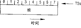
Fig. 4 shows the typical structure of time slot of the frame among Fig. 3.
Fig. 5 shows typical 1/4th bit architecture of the time slot among Fig. 4.
Fig. 6 shows the relative section according to the travelling carriage with downlink observed time difference measurements ability of one embodiment of the invention.
Fig. 7 shows how to determine typical down link monitor window according to the present invention.
Fig. 8 shows the relative section according to the travelling carriage with downlink observed time difference measurements ability of an alternative embodiment of the invention.
Describe in detail
Fig. 2 shows an example according to the relative section of the wireless communication system that comprises the downlink observed time difference measurements ability of the present invention.Realize in the GSM network of the present invention in Fig. 2 example.As shown in Figure 2, GSM moving exchanging center MSC and a plurality of base station controller BSC communicate to connect, and described BSC communicates with one or more base transceiver station BTS successively.Base transceiver station can carry out radio communication via air interface and a plurality of mobile station MS.Via BSC with BTS and communicating by letter from MSC to MS is well-known in the prior art.
Fig. 2 also comprises and utilizes traditional GSM signaling protocol and moving exchanging center MSC to carry out the mobile positioning center MLC that two-way communication is connected.In Fig. 2, MLC can receive the request that the position to mobile station MS 1 positions.Such request normally receives from the position application 21 that communicates to connect with MLC.Position application 21 can be node or the outside position application in the scope of network own.The request that the position of mobile station MS 1 positions is reacted, thereby MLC inquiry network is determined serving BTS 23 (promptly serving the GSM sub-district), and which BTS decision should select be used for downlink observed time difference measurements.
Then, MLC can produce the locating request message that is used for mobile station MS 1, and the latter indicates the frequency of the selected base transceiver station that is monitored and the real-time poor RTD between BSIC (BSIC obtains in a conventional manner) and serving BTS and each the selected BTS in such as the GSM network of network.Locating request message can be sent to MS1 from MLC via the air interface between MSC, BSC21, BTS23 and BTS21 and the MS1.Because MS1 knows synchronization burst and will when arrives from its oneself serving BTS, thereby MS1 can utilize RTD information to come the approximate calculation synchronization burst when to arrive from selected contiguous BTS.Hereinafter this point will be described in more detail.
During call setup for example, above-mentioned information can also send to MS1 as specific messages.And above-mentioned information can also send to MS1 by Broadcast Control Channel termly as system information.Can utilize from the OTD information of benchmark travelling carriage reception by MLC and calculate RTD, as mentioned above, maybe can utilize other traditional technology to provide RTD to MLC.
Fig. 3 to 5 shows the real-time poor notion between the base transceiver station in such as the GSM of the typical GSM network portion of Fig. 2.
The frame structure that Fig. 3 shows a pair of base transceiver station that is denoted as BTS2 and BTS1 among Fig. 3 poor in real time between regularly.In GSM, the tdma frame that base transceiver station uses is numbered with recirculation mode, and each circulation (being also referred to as superframe (hyperframe)) comprises and is numbered 2715648 frames of frame 0 to frame 2715647.In the example of Fig. 3, the frame 0 of BTS1 and the frame 828 of BTS2 (timewise) in time are overlapping.
Refer now to Fig. 4, each tdma frame among the GSM is divided into eight time slot TS, is numbered time slot 0 to time slot 7.As shown in Figure 5, each GSM time slot also is divided into 625 1/4th bit QB, and therefore during each time slot, always total 625/4=156.25 bit is sent out.Therefore, real-time poor between BTS2 and the BTS1 is expressed as tlv triple (FND in a conventional manner, TND, QND), wherein FND is poor (FN2-FN1) between the tdma frame number of BTS2 and BTS1, TND is poor (TN2-TN1) between the timeslot number number of BTS2 and BTS1, and QND is poor (QN2-QN1) between 1/4th bit number numbers of BTS2 and BTS1.For example, referring to figs. 3 to 5, if 1/4th bits 0 of the time slot 0 of the frame of BTS1 0 are aimed at 1/4th bits 37 of the time slot 6 of the frame 828 of BTS2 in time, then the real-time poor RTD between BTS2 and the BTS1 is by tlv triple (FN2-FN1, TN2-TN1, QN2-QN1) provide, wherein NF2, TN2 and QN2 are frame number number, timeslot number number and 1/4th bit number numbers of BTS2, and NF1, TN1 and QN1 are frame number number, timeslot number number and 1/4th bit number numbers of BTS1.Like this, described tlv triple is that (828-0,6-0 37-0), or are (828,6,37) simply.
When mobile station MS 1 receives its oneself serving base transceiver station (for example BTS1 of Fig. 3) and another and will carry out real-time poor RTD between the base transceiver station (for example BTS2 Fig. 3) that down link measures the time of advent from MLC, known frame structure timing (FN1 with serving base transceiver station BTS1, TN1, QN1) together, mobile station MS 1 can use RTD tlv triple (FND, TND QND) determines with respect to BTS1 frame structure BTS2 frame structure regularly regularly.(the current frame number of BTS2 QN1) is counted NF2 for FN1, TN1 for mobile station MS 1 can carry out following calculating when determining BTS1 in the base any set point.
QN2 '=QN1+QND (formula 2)
TN2 '=TN1+TND+ (QN2 ' div625) (formula 3)
FN2 '=FN1+FND+ (TN2 ' div8) (formula 4)
FN2=FN2 ' mod2715648 (formula 5)
In the superincumbent equation, " div " division of integer, " mod ' be mould n division, " x mod n "=" x is divided by the remainder of n " wherein.
Synchronization burst SB among the GSM comprises 78 information encoded bits and 64 predetermined bit training sequences, in prior art well-known.78 information encoded bits comprise BSIC and so-called normalization frame number number (reduced frame number), are expressed as three fractional t1s, T2 and T3 ' in a conventional manner.Be expressed as follows at the frame number number (FN) of synchronization burst SB and the conventional relationship between parameter T1, T2 and the T3 ':
TI=FN div (26 * 51) (formula 6)
T2=FN mod26 (formula 7)
T3=FN mod51 (formula 8)
The div10 (formula 9) of T3 '=(T3-1)
Like this, in case the current frame number of BTS2 is counted FN2 with respect to equation 2 to 5 and according to after the calculating shown in top, then can determine parameter T3 by FN2 being inserted into top equation 8.
In traditional GSM network, synchronization burst SB appears in the frame 1,11,21,31 and 41 time slot 0 of 51-frame repetitive sequence of the tdma frame that BCCH (Broadcast Control Channel) carrier wave by BTS sends.Like this, top T3 represents that present frame FN2 is arranged in 51-frame repetitive sequence.Because, as mentioned above, synchronization burst SB appears in the frame 1,11,21,31 and 41 time slot 0 of described 51-frame repetitive sequence, thereby the next T3 (claiming that it is T3n) that satisfies relation (T3-1) mod10=0 will represent the frame of next synchronization burst SB with the BTS2 of appearance.So determine corresponding frame number number (claiming that it is FN2n) by following formula:
FN2n=(FN2+DT3) mod2715648 (formula 10)
DT3=(T3n-T3) mod51 wherein.
Now, can be by FN2n being inserted into equation 6 and 7 and T3n is inserted into equation 9 determines parameter T1, T2 and T3 '.According to GSM standard, parameter T1, T2 can utilize 25 bits to represent with BSIC with T3 '.Can determine the BSIC bit from the BSIC information that receives at MS1, and can determine the bit of expression T1, T2 and T3 ' according to equation 6,7 and 9.So mobile station MS 1 can be applicable to 25 above-mentioned bits, the well-known encryption algorithm that promptly illustrates in the GSM standard (ETSI GSM standard 05.03) is so that 78 coded-bits from these 25 bits generation synchronization burst.
Like this, with regard to its oneself serving BTS 1 frame structure regularly with regard to, mobile station MS 1 frame number that it is now know that the BTS2 of synchronization burst will occur is counted FN2n.As mentioned above, synchronization burst always appears at time slot 0, so mobile station MS 1 knows definitely that now when BTS2 will send synchronization burst.And mobile station MS 1 is also known all 78 bits and all 64 training bits of synchronization burst now.142 bits rather than 64 bits have only been known, have compared that travelling carriage can obtain higher precision when arriving time measurement with the conventional situation of only knowing 64 bits.And, 142 known bits have been arranged, mobile station MS 1 might obtain under the bigger noise circumstance and utilizing 64 identical precision of the resulting precision of bit under lower noise circumstance.
Because mobile station MS 1 does not know that with respect to the position of given contiguous BTS (for example BTS28 among Fig. 2) therefore the synchronization burst SB from that BTS will can not arrive described mobile station MS 1 at the precise time that described travelling carriage calculates.Fig. 7 shows and how search window is defined as expecting that the time of synchronization burst arrival mobile station MS 1 is included in interior example.Make FN represent the frame number number of expection from the next SB (SB2) of vicinity (non-service) BTS2 arrival.Can obtain calculating the method for such frame number number from equation 10.MS1 knows when the corresponding SB (SB1) with identical frame number number will arrive or when arrive from serving BTS 1 from serving BTS 1.With respect to the time base of described travelling carriage, represent that with T0 this constantly.
MS1 is in the circle 71.For example can determine or derive the radius of described circle by radius of society from Timing Advance.Consider two kinds of opposite extreme situations.A kind of extreme case is MS1 in 74 situation.Because SB2 transmits and transmits d12 far away than SB1, so SB2 arrives at time T 0+RTD+d12/c.Another opposite extreme situations is that MS1 is 75.So SB2 arrives at time T 0+RTD+ (d12-2r)/c.Like this, when described travelling carriage is between 75 and 74, SB2 in window [T0+RTD+ (d12-2r)/c-k, T0+RTD+d12/c+k], the wherein RTD that provided of k explanation and the error of d12 value.
Because RTD is known, when MS 1 can will arrive with the SB2 of certain uncertain prediction from BTS2 (non-service).
Compare when not knowing the time of advent fully, the ability of calculating search window allows to detect synchronization burst with higher reliability, and compares with the travelling carriage of prior art, and the complexity of described travelling carriage reduces.For example, can receive and store data in real time from whole search window, be used for the processing of back, owing to must utilize traditional technology to guarantee to catch synchronization burst, if search window needs 10 tdma frames long, then above-mentioned real-time reception and storage are in fact infeasible from the data of whole search window.In addition, search window makes and can reduce whole Measuring Time.
Utilize RTD knowledge to come zero-computing time and the search window that is used for synchronization burst SB to reduce significantly and carry out the Measuring Time that down link OTD measures.If do not receive RTD information, travelling carriage needs continuously to search for as usual, happen suddenly up to detecting frequency correction, so travelling carriage knows that synchronization burst will occur at next frame.Because RTD information is corresponding to all base transceiver stations to be measured, thereby travelling carriage can dispatch various measurements and Looking Out Time is limited in the search window period, and this utilizes prior art not reach.
Fig. 6 shows the typical implementation according to the relative section of the mobile station MS 1 of Fig. 2 that is used for carrying out downlink observed time difference measurements of the present invention.Described travelling carriage comprises synchronization burst determiner (determiner) 61, and the latter receives the frequency that is used for each selected base transceiver station that OTD measures as input (for example via MSC, BSC21 and the BTS23 MLC from Fig. 2), BSIC and with respect to the RTD of serving base transceiver station.The synchronization burst determiner also receives the information about the distance between its serving base transceiver station and all the neighbor base station transceiver stations, together with the radius of society information of all neighbor base station transceiver stations.This information can be upgraded (when MS1 roams) termly by MLC, and is stored among Fig. 6 in the memory shown in 63, and perhaps, described information can be included in by MLC and offer in the locating request message of synchronization burst determiner.
The approximate Expected Arrival Time of base 60 when synchronization burst determiner 61 is determined synchronization burst with respect to Serving cell (serving base transceiver station) frame structure for each selected BTS, and export to monitor 65 time of advent 64 these information.And 64, the synchronization burst determiner to described time of advent monitor export 78 of the synchronization burst of each selected BTS and encrypt bits and 64 training bits.The synchronization burst determiner also is that each selected base transceiver station calculates search window, and exports to the monitor time of advent 62 these search window information.
The time of advent, monitor was to arriving time measurement at 68 signals that receive from BTS.Monitor can utilize the information time of advent, window information and the 142 bit sequence information of calculating and each selected base transceiver station was arrived time measurement the time of advent.This information has been arranged, and the time of advent, monitor can be dispatched various measurements effectively, and if necessary, can catch and store the signal that receives during each search window, handled these information in the time of back then.The received signal that the mode of describing in detail in the U.S. Patent application U.S. series number 08/978960 of pending trial in the time of can be with any required traditional approach or with incorporated herein by reference 26 days November in 1997 application is used for determining the time of advent is handled.
Carry out measure the required time of advent after, the time of advent monitor can 66 to MLC (via BTS23, BSC21 and MSC) output or the time of advent information or observed time difference information.MLC utilizes this information to determine the position of mobile station MS 1 in a conventional manner then, and the request that described then position offers in suitable message among Fig. 2 uses 21.In addition, if MS1 knows the geographical position of tested BTS, then MS1 can calculate its oneself position.
Measure although describe the OTD of relevant GSM synchronization burst above in detail, yet should be understood that technology of the present invention also can be applicable to the burst of various other forms.
In such as above-mentioned those cdma system, provide RTD information to cause remarkable improvement to known down link OTD technology to travelling carriage.Travelling carriage can utilize RTD information to calculate the search window of relevant Fig. 7 usually in the above described manner.Because the timing difference between travelling carriage it is now know that its serving base transceiver station and each neighbor base station transceiver station, therefore can utilize the geometry of Fig. 7 to determine the search window of each neighbor base station transceiver station as described above.
Then, for given base transceiver station, only during FSC and SSC anticipated signal arrive the search window of described travelling carriage, need to carry out the FSC peak value and detect relevant with relevant SSC.And, because not only identifying described travelling carriage, RTD information should when monitor that the signal from given base transceiver station arrives, but also identification base transceiver station and its code character, so described travelling carriage can be determined the SSC sign indicating number type relevant with described base transceiver station inferentially.Like this, for interested base transceiver station, can side by side carry out the FSC peak value detect relevant with FSC-SSC, thereby the relevant FSC peak value detection above-mentioned known technology afterwards that must be connected on FSC-SSC compare, advantageously significantly reduce acquisition time.The feasible collection of the minimizing of acquisition time arrives the corresponding minimizing of idling cycle length during the temporal information.The minimizing of this idling cycle has improved the downlink capability of network.
As the further result of the inferenctial knowledge of the SSC sign indicating number type of travelling carriage, do not need the FSC peak value relevant with several SSC sign indicating number types, as in known technology.This has reduced memory and the calculation requirement in the travelling carriage.
Because it is relevant with FSC-SSC to carry out the detection of FSC peak value simultaneously, so can make up this two kinds of operating results at each time slot, this provides the signal strength signal intensity of enhancing and has therefore strengthened audibility.
Because each base transceiver station that is monitored is set up search window, thereby reduced the probability of selecting signal from wrong base transceiver station significantly.In addition, be correlated with, thereby also reduced both rates of selecting false peaks because only near true peak, carry out.
Provide another advantage of RTD information to be to travelling carriage: RTD information and corresponding search window have been arranged, and travelling carriage can join with the signal correction except that FSC and SSC.For example, not or except that FSC/SSC that travelling carriage can be associated with the broadcast channel of base transceiver station (for example broadcast channel of showing to discern from the neighbour of neighbor base station transceiver station).With RTD information, network can be discerned each code character of described base transceiver station and each long (expansion) sign indicating number of described broadcast channel for travelling carriage.Travelling carriage can utilize traditional technology to produce the whole long code (for example 40960 chips) of the broadcast channel of given base transceiver station from described code group identification information and long code identifying information.
Broadcast channel, the Common Control Physical Channel of for example above-mentioned WCDMA communication system (CCPCH) has the power level that adds the identical magnitude of SSC signal power sum with fsc signal power usually.And this broadcast channel sends continuously, rather than has only 10 time transmission as FSC/SSC.Therefore, the signal of broadcast channel comprises the energy more much bigger than FSC/SSC signal.This more high-octane level provides the audibility of enhancing and makes and can gather quickly.
Because broadcast channel signal is sent continuously, thus make can Billy with FSC/SSC obtainable higher idling cycle utilization.For example, at any given time slot, broadcast channel provides and decuples the symbol that is used to be correlated with that FSC/SSC can provide.This makes and can use than weak point and/or than the small frequency idling cycle, has therefore further improved the downlink capability of network.
Because broadcast channel is only represented one " sign indicating number ", the required memory space of incoherent combination is half of memory space required during FSC relevant with SSC (two sign indicating numbers).And near identical base transceiver station will have unique broadcast channel, select the probability of wrong base transceiver station to ignore.Described unique channel provides than cross-correlation performance much better under the FSC/SSC situation (lower cross correlation), much smaller when therefore selecting the likelihood ratio of false peaks to utilize the FSC/SSC situation.
Fig. 8 illustrates the relative section of the typical travelling carriage that can carry out down link OTD measurement in such as above-mentioned cdma system.This cdma system can have and identical structure shown in Figure 2 usually, but has the air interface that realizes according to CDMA or WCDMA technology.Travelling carriage shown in Figure 8 comprises the input 81 that is used for receiving from network (being the MLC of Fig. 2) RTD information, and the described travelling carriage of described RTD information representation will carry out poor in real time between serving base transceiver station that down link OTD measures and each neighbor base station transceiver station to it.Input 81 also receives the code group identification information that is used for each base transceiver station from network.Broadcast channel is among the measured embodiment therein, except that code group identification information, and the long code identifying information that the broadcast channel that input 81 receives each base transceiver station is used.
Window determiner 83 receives RTD information from network, calculates search window about Fig. 7 in above-described mode usually, and arrives (TOA) monitor 85 output window information to the CDMA time.Monitor 85 is carried out required operation (for example peak value detects with relevant), measures so that produce the time of advent that is used for each required base transceiver station.
In an embodiment who utilizes FSC/SSC to monitor, code generator 87 receives the code group identification information that is used for each base transceiver station from input 81, produces SSC sign indicating number type thus, and 84 these SSC sign indicating number types is offered monitor 85.Broadcast channel is with among another measured embodiment therein, the long code identifying information that the broadcast channel that code generator 87 also receives each base transceiver station from input 81 is used, code group identification information and long code identifying information are reacted and produced long code, and provide described long code to monitor 85 84.
Monitor 85, and carries out required time of advent and measures in 89 monitoring of CDMA air interfaces according to search window.Monitor 85 can be 86 to network output or TOA information or OTD information.Network (for example MLC of Fig. 2) can utilize this information to determine the position of described travelling carriage in a conventional manner.In addition, if travelling carriage is known the geographical position of tested base transceiver station, then described travelling carriage can calculate its oneself position.
Window determiner 83 can receive information about distance between its serving base transceiver station and all the neighbor base station transceiver stations together with the radius of society information that is used for all neighbor base station transceiver stations, so that help described window determiner to determine described search window.MLC can upgrade described range information (when travelling carriage is roamed) termly, and is stored among Fig. 8 in the memory shown in 82, and perhaps described information can be included in by MLC and send in the locating request message of described travelling carriage.The approximate Expected Arrival Time that is monitored signal of base 80 when the window determiner utilizes RTD information to determine with respect to serving base transceiver station for each base transceiver station that is monitored, and described Expected Arrival Time information combined with described range information, so that produce suitable search window.
It will be apparent to one skilled in the art that by suitably revise at the data processing section of traditional travelling carriage hardware, software or software and hardware both, can easily realize the typical travelling carriage part among Fig. 6 and Fig. 8.
In view of top explanation, should be clear, by the more known bits from synchronization burst SB are provided to travelling carriage, downlink observed time difference technology of the present invention has improved risk, the minimizing of the sensitivity of downlink observed time difference measurements, the accuracy that improves the time of advent and observed time difference measurements, minimizing measurement mistake and has carried out the required time of necessary measurement and need less memory span of travelling carriage and lower data-handling capacity.
Claims (40)
1. method of utilizing mobile service station (MS1) in the cordless communication network to measure in the described network respectively the time of advent of each radio signal that sends by a plurality of radio transmitters (23,28), described method comprises:
Provide the described radio signal of expression expection when to arrive the information of described mobile service station;
Described mobile service station is reacted to described information and the arrival of supervision (85) described radio signal during the search window period; With
During the described search window period, described mobile service station is carried out radio signal relevant with the true peaks of at least one radio transmitter of serving described mobile service station simultaneously.
2. the method for claim 1, it is characterized in that: the described information that provides step to comprise to provide described each radio signal of expression expection to arrive each period of described mobile service station, and described monitoring step comprises that described mobile service station monitors the arrival of each radio signal during the corresponding period.
3. the method for claim 1 is characterized in that the described step that provides also comprises:
Provide real-time poor information, the difference the when latter represents to serve each of time base (80) that the radio transmitter of described mobile service station uses and just measured radio transmitter use between base; With
Described poor in real time (RTD) information is reacted, with respect to described service radio transmitter use described the time base determine that described each radio signal of (83) expection arrives a plurality of time points (74,75) of described mobile service station.
4. the method for claim 3, it is characterized in that: describedly provide step also to comprise to utilize described time point to determine that described each radio signal of expection arrives each period of described mobile service station, and described monitoring step comprises that described mobile service station monitors the arrival of each radio signal during the corresponding period.
5. the method for claim 4 is characterized in that the described step of utilizing comprises that described mobile service station utilizes described time point to determine described each period.
6. the method for claim 4 is characterized in that the described step of utilizing comprises the respective distance (82) of considering that described radio signal is propagated for arriving described mobile service station.
7. the method for claim 6 is characterized in that described consideration step comprises the possible propagation distance of each radio signal being estimated maximum possible propagation distance and minimum.
8. the method for claim 7, it is characterized in that described consideration step comprises: to each radio signal, set up the starting point (74) of relevant period according to the time point of described expection arrival and the possible propagation distance of described minimum, and set up the end point (75) of relevant period according to the time point of described expection arrival and the possible propagation distance of described maximum.
9. the method for claim 3 is characterized in that described determining step comprises that described mobile service station determines described time point.
10. the method for claim 3, it is characterized in that in the time division multiple access channel sending described radio signal, and the described step that real-time poor information is provided comprise utilize frame number count at least one in differing from of poor, timeslot number number (TS) difference and 1/4th bit number numbers (QB) represent poor in real time.
11. the method for claim 1 is characterized in that described communication network is a cellular communications networks.
12. the method for claim 11 is characterized in that described communication network is the GSM network.
13. claim 1 method is characterized in that described radio signal is code division multiple access (CDMA) signal.
14. the method for claim 13, it is characterized in that comprising the information that the extended code that expression used by described radio transmitter respectively is provided, and described mobile service station determines the extended code that described each radio transmitter uses from described extended code information, and described monitoring step comprises the radio signal of utilizing described extended code to monitor the broadcast channel relevant with described each radio transmitter.
15. the method for claim 13 is characterized in that described monitoring step comprises:, relevant with first yard that regularly sends by described relevant radio transmitter described radio signal to each radio signal; And with described correlation step side by side, described radio signal with comprise that to continue a plurality of second yard sign indicating number type of sending by described relevant radio transmitter relevant, make one of described regular transmission with described first yard side by side send in the described yard type each described second yard.
16. the method for claim 15 is characterized in that comprising the information that each radio transmitter is provided the code character under the described radio transmitter of expression, and also comprises described mobile service station that described code group information is reacted and determine described sign indicating number type.
17. the method for claim 15 is characterized in that comprising by the result who makes up described correlation step and detects first and second yards of described transmission.
18. a method of determining mobile service station (MS1) position in cordless communication network, it comprises:
Measure in the described network respectively by a plurality of radio transmitters (23 in described mobile service station, 28) each time of advent of the radio signal of Fa Songing, comprise the information that provides the described radio signal of expression expection when to arrive described mobile service station, and described mobile service station is reacted to described information and the arrival of supervision (85) described radio signal during the search window period;
During the described search window period, the signal correction of true peaks of at least one radio transmitter of described mobile service station is carried out and is served in described mobile service station simultaneously; With
Utilize the position of determining described mobile service station the time of advent of described measurement.
19. the method for claim 18 is characterized in that described radio signal code division multiple access (CDMA) signal.
20. determine in the radio communication platform (MS1) in being operated in cordless communication network that radio signal reaches time method, it comprises:
From described cordless communication network acquired information (63), wherein can determine the information content of described radio signal but described information itself is not showed the described information content of described radio signal by described information;
Described information is reacted and determine the described information content of (61) described radio signal; With
The time of advent of utilizing the described information content of described radio signal to measure described radio signal,
Wherein, described information comprises the transmission information regularly of representing described radio signal, this transmission timing information is poor in real time (RTD) information, time the difference between the base that the latter represents that the time base (60) that described radio communication platform is known and the radio transmitter (23) that will send described radio signal use.
21. the method for claim 20 is characterized in that described information comprises that expression will send the information of the radio transmitter of described radio signal.
22. the method for claim 21 is characterized in that described communication network is the GSM network, and represents that the described information of described radio transmitter comprises the base station identity code (BSIC) of discerning the base station in the described GSM network.
23. a device that is used for determining the cordless communication network position of mobile communication station, it comprises:
Be used for determining when each radio signal of a plurality of radio signals of expection arrives the determiner (61) of described mobile service station; With
Be used to measure the radio signal monitor (65) of each time of advent of described radio signal, described monitor is arranged in the described mobile service station and has the input that is connected to described determiner, in order to receive the information when described radio signal of expression expection arrives described mobile service station thus, during the search window period, described monitor is reacted to described information and is monitored the arrival of described radio signal
Wherein, described determiner comprises the input of poor in real time (RTD) information of the difference between the base when being used to receive expression serves each of the radio transmitter of described mobile service station time base (60) that uses and radio transmitter (23) use that sends described radio signal, described determiner is reacted to described real-time poor information and is determined that with respect to the time base that described service radio transmitter uses described each radio signal of expection arrives a plurality of time points (74,75) of described mobile service station.
24. the device of claim 23 is characterized in that described determiner is arranged in the described mobile service station.
25. the device of claim 23 is characterized in that described each radio signal of the definite expection of described determiner arrives each period of described mobile service station.
26. the device of claim 23 is characterized in that described determiner can utilize described time point to determine that described each radio signal of expection arrives the corresponding period of described mobile service station.
27. the device of claim 26, it is characterized in that described determiner can consider the respective distance (63) that described radio signal is propagated for arriving described mobile service station between regularly really in the described period, described determiner can be estimated maximum possible propagation distance and minimum possible propagation distance, and for each radio signal, set up the starting point (74) of relevant period according to the described time point that expection arrives with minimum possible propagation distance, and set up the end point (75) of relevant period with maximum possible propagation distance according to the described time point that expection arrives.
28. the device of claim 23 is characterized in that described communication network is a cellular communications networks.
29. the device of claim 28 is characterized in that described communication network is the GSM network.
30. the device of claim 23 is characterized in that described radio signal is code division multiple access (CDMA) signal.
31. the device of claim 30 is characterized in that comprising the code generator that is connected to described radio signal monitor, is used for being provided for monitoring to described monitor the sign indicating number of described radio signal.
32. the device of claim 31 is characterized in that described sign indicating number comprises relevant with described radio signal respectively extended code.
33. the device of claim 31 is characterized in that described code generator comprises the input of receiving code identifying information, described sign indicating number responds described sign indicating number identifying information and provides.
34. the device of claim 31 is characterized in that described code generator is arranged in the described mobile service station.
35. the device of claim 31 is characterized in that described sign indicating number comprises the sign indicating number that is carried by described radio signal.
36. the device of claim 35 is characterized in that described sign indicating number comprises respectively and the relevant sign indicating number pattern of radio transmitter that is used for producing described each radio signal.
37. a device that is used to measure the time of advent of radio signal, it comprises:
The input (81) that is used to the information that receives wherein can determine the information content of described radio signal by described information, but described information itself can not be showed the information content of described radio signal;
Be connected to described input and described poor in real time (RTD) information is reacted with the determiner (83) of the information content of determining described radio signal, and be used for calculating and measure search window; With
Be used to measure the described radio signal radio signal monitor (85) of the time of advent, described monitor is connected to described determiner, be used in the information content of utilizing described radio signal the time of advent of measuring described radio signal, and during the described search window period, monitor the arrival of described radio signal
Wherein, described information comprises the transmission information regularly of representing described radio signal, and this transmissions timing information is time poor in real time (RTD) information of difference between the base of the time base (80) known of the described device of expression and radio transmitter (23) use that will send described radio signal.
38. the device of claim 37 is characterized in that described device is mobile radio platform (MS1).
39. the device of claim 37 is characterized in that described information comprises that expression will send the information of the radio transmitter of described radio signal.
40. the device of claim 39 is characterized in that described communication network is the GSM network, and represents that the described information of described radio transmitter comprises the base station identity code (BSIC) of discerning base station in the described GSM network.
Applications Claiming Priority (4)
| Application Number | Priority Date | Filing Date | Title |
|---|---|---|---|
| US09/131,150 | 1998-08-07 | ||
| US09/131,150 US6490454B1 (en) | 1998-08-07 | 1998-08-07 | Downlink observed time difference measurements |
| US09/186,192 | 1998-11-04 | ||
| US09/186,192 US6356763B1 (en) | 1998-08-07 | 1998-11-04 | Downlink observed time difference measurements |
Publications (2)
| Publication Number | Publication Date |
|---|---|
| CN1322452A CN1322452A (en) | 2001-11-14 |
| CN1127880C true CN1127880C (en) | 2003-11-12 |
Family
ID=26829185
Family Applications (1)
| Application Number | Title | Priority Date | Filing Date |
|---|---|---|---|
| CN 99811740 Expired - Lifetime CN1127880C (en) | 1998-08-07 | 1999-07-27 | Improvements in downlink observed time difference measurements |
Country Status (9)
| Country | Link |
|---|---|
| EP (1) | EP1103156B1 (en) |
| JP (1) | JP4309587B2 (en) |
| CN (1) | CN1127880C (en) |
| AU (1) | AU772999B2 (en) |
| BR (1) | BR9912770B1 (en) |
| CA (1) | CA2338544C (en) |
| RU (1) | RU2225079C2 (en) |
| TW (1) | TW475339B (en) |
| WO (1) | WO2000008886A1 (en) |
Families Citing this family (12)
| Publication number | Priority date | Publication date | Assignee | Title |
|---|---|---|---|---|
| US6490454B1 (en) | 1998-08-07 | 2002-12-03 | Telefonaktiebolaget Lm Ericsson (Publ) | Downlink observed time difference measurements |
| US6665540B2 (en) * | 2001-02-02 | 2003-12-16 | Nokia Mobile Phones, Ltd. | Method and system for locating a mobile terminal in a cellular radio network |
| US7363043B2 (en) | 2001-05-18 | 2008-04-22 | Southwest Research Institute | Passive GSM-based self-locating device |
| US6876859B2 (en) * | 2001-07-18 | 2005-04-05 | Trueposition, Inc. | Method for estimating TDOA and FDOA in a wireless location system |
| GB2392801B (en) * | 2001-11-05 | 2005-08-17 | Nokia Corp | A method for identification of base stations and for checking measurement values of an observed time difference between transmissions from base stations |
| CN101334463B (en) * | 2008-07-29 | 2010-05-12 | 北京航空航天大学 | Time parameter analogue method in GNSS navigation signal simulator |
| US8699453B2 (en) | 2009-02-02 | 2014-04-15 | Qualcomm Incorporated | Reuse of RF receive chain for hand-in assistance |
| TWI412777B (en) * | 2009-06-19 | 2013-10-21 | Htc Corp | Method of enhancing positioning measurement and related communication device |
| CN101806907B (en) * | 2010-03-12 | 2012-09-05 | 清华大学 | Coherent and incoherent mixed aircraft positioning method under multi-station and multi-platform system |
| GB2539364A (en) * | 2014-10-02 | 2016-12-21 | Aeroscout Ltd | Location system |
| TWI667908B (en) * | 2016-02-01 | 2019-08-01 | 日商日本電氣股份有限公司 | Time difference measuring device, system and method |
| WO2019173875A1 (en) * | 2018-03-14 | 2019-09-19 | Locata Corporation Pty Ltd | Method and apparatus for synchronising a location network |
Family Cites Families (3)
| Publication number | Priority date | Publication date | Assignee | Title |
|---|---|---|---|---|
| JP3399623B2 (en) * | 1994-03-16 | 2003-04-21 | 富士通株式会社 | Mobile station position acquisition device |
| GB9508884D0 (en) * | 1995-05-02 | 1995-06-21 | Telecom Sec Cellular Radio Ltd | Cellular radio system |
| US5508708A (en) * | 1995-05-08 | 1996-04-16 | Motorola, Inc. | Method and apparatus for location finding in a CDMA system |
-
1999
- 1999-07-27 RU RU2001106637/09A patent/RU2225079C2/en active
- 1999-07-27 BR BRPI9912770-9A patent/BR9912770B1/en active IP Right Grant
- 1999-07-27 CA CA002338544A patent/CA2338544C/en not_active Expired - Lifetime
- 1999-07-27 JP JP2000564407A patent/JP4309587B2/en not_active Expired - Lifetime
- 1999-07-27 EP EP99943545A patent/EP1103156B1/en not_active Expired - Lifetime
- 1999-07-27 CN CN 99811740 patent/CN1127880C/en not_active Expired - Lifetime
- 1999-07-27 AU AU56617/99A patent/AU772999B2/en not_active Expired
- 1999-07-27 WO PCT/SE1999/001322 patent/WO2000008886A1/en active IP Right Grant
- 1999-08-02 TW TW88113177A patent/TW475339B/en not_active IP Right Cessation
Also Published As
| Publication number | Publication date |
|---|---|
| BR9912770B1 (en) | 2014-06-17 |
| JP4309587B2 (en) | 2009-08-05 |
| CA2338544C (en) | 2010-01-12 |
| CN1322452A (en) | 2001-11-14 |
| AU5661799A (en) | 2000-02-28 |
| TW475339B (en) | 2002-02-01 |
| EP1103156A1 (en) | 2001-05-30 |
| AU772999B2 (en) | 2004-05-13 |
| BR9912770A (en) | 2001-05-08 |
| WO2000008886A1 (en) | 2000-02-17 |
| RU2225079C2 (en) | 2004-02-27 |
| JP2002522991A (en) | 2002-07-23 |
| EP1103156B1 (en) | 2011-11-30 |
| CA2338544A1 (en) | 2000-02-17 |
Similar Documents
| Publication | Publication Date | Title |
|---|---|---|
| US6356763B1 (en) | Downlink observed time difference measurements | |
| US10694517B2 (en) | Methods and systems for providing enhanced position location in wireless communications | |
| EP1869802B1 (en) | Method and apparatus for beacon discovery in a spread spectrum cellular radio communication system | |
| CN1249935C (en) | Cyclic cell search | |
| US7113782B2 (en) | Method and device for selecting parameters for a cellular radio communication network based on occurrence frequencies | |
| US6246884B1 (en) | System and method for measuring and locating a mobile station signal in a wireless communication system | |
| CN1091564C (en) | Pilot signal researching technique for cellular communications system | |
| CN1200589C (en) | Improved soft handoff algorithm and wireless communication system for third generation CDMA systems | |
| CN1127880C (en) | Improvements in downlink observed time difference measurements | |
| CN1267439A (en) | Method for identifying base station of time division cellular network in mobile station and mobile station | |
| CN1235440C (en) | Method and apparatus for link quality estimation in mobile communication network | |
| JP2003522448A (en) | Mobile communication network | |
| CN1913703A (en) | Method and system for correcting RTT measuring valve by multi-sector cell | |
| CN1860817A (en) | Estimation of signal delay | |
| US7024193B2 (en) | Method and apparatus for performing identification of measurement channels in TDMA E-OTD | |
| CN1859745A (en) | Synchronous method in broad band CDMA network common frequency switching | |
| CN1867178A (en) | Cell identification positioning method | |
| CN1535071A (en) | Method of mobile station location and location unit thereof |
Legal Events
| Date | Code | Title | Description |
|---|---|---|---|
| C06 | Publication | ||
| PB01 | Publication | ||
| C10 | Entry into substantive examination | ||
| SE01 | Entry into force of request for substantive examination | ||
| C14 | Grant of patent or utility model | ||
| GR01 | Patent grant | ||
| CX01 | Expiry of patent term | ||
| CX01 | Expiry of patent term |
Granted publication date: 20031112 |