CN112780728B - Cylindrical ring groove type double cycloid small tooth difference planetary reducer - Google Patents
Cylindrical ring groove type double cycloid small tooth difference planetary reducer Download PDFInfo
- Publication number
- CN112780728B CN112780728B CN202110018201.4A CN202110018201A CN112780728B CN 112780728 B CN112780728 B CN 112780728B CN 202110018201 A CN202110018201 A CN 202110018201A CN 112780728 B CN112780728 B CN 112780728B
- Authority
- CN
- China
- Prior art keywords
- tooth
- cylindrical ring
- gear
- planet wheel
- planet
- Prior art date
- Legal status (The legal status is an assumption and is not a legal conclusion. Google has not performed a legal analysis and makes no representation as to the accuracy of the status listed.)
- Active
Links
Images


Classifications
-
- F—MECHANICAL ENGINEERING; LIGHTING; HEATING; WEAPONS; BLASTING
- F16—ENGINEERING ELEMENTS AND UNITS; GENERAL MEASURES FOR PRODUCING AND MAINTAINING EFFECTIVE FUNCTIONING OF MACHINES OR INSTALLATIONS; THERMAL INSULATION IN GENERAL
- F16H—GEARING
- F16H1/00—Toothed gearings for conveying rotary motion
- F16H1/28—Toothed gearings for conveying rotary motion with gears having orbital motion
- F16H1/32—Toothed gearings for conveying rotary motion with gears having orbital motion in which the central axis of the gearing lies inside the periphery of an orbital gear
-
- F—MECHANICAL ENGINEERING; LIGHTING; HEATING; WEAPONS; BLASTING
- F16—ENGINEERING ELEMENTS AND UNITS; GENERAL MEASURES FOR PRODUCING AND MAINTAINING EFFECTIVE FUNCTIONING OF MACHINES OR INSTALLATIONS; THERMAL INSULATION IN GENERAL
- F16H—GEARING
- F16H57/00—General details of gearing
- F16H57/02—Gearboxes; Mounting gearing therein
- F16H57/021—Shaft support structures, e.g. partition walls, bearing eyes, casing walls or covers with bearings
-
- F—MECHANICAL ENGINEERING; LIGHTING; HEATING; WEAPONS; BLASTING
- F16—ENGINEERING ELEMENTS AND UNITS; GENERAL MEASURES FOR PRODUCING AND MAINTAINING EFFECTIVE FUNCTIONING OF MACHINES OR INSTALLATIONS; THERMAL INSULATION IN GENERAL
- F16H—GEARING
- F16H57/00—General details of gearing
- F16H57/02—Gearboxes; Mounting gearing therein
- F16H57/023—Mounting or installation of gears or shafts in the gearboxes, e.g. methods or means for assembly
-
- F—MECHANICAL ENGINEERING; LIGHTING; HEATING; WEAPONS; BLASTING
- F16—ENGINEERING ELEMENTS AND UNITS; GENERAL MEASURES FOR PRODUCING AND MAINTAINING EFFECTIVE FUNCTIONING OF MACHINES OR INSTALLATIONS; THERMAL INSULATION IN GENERAL
- F16H—GEARING
- F16H57/00—General details of gearing
- F16H57/02—Gearboxes; Mounting gearing therein
- F16H57/031—Gearboxes; Mounting gearing therein characterised by covers or lids for gearboxes
-
- F—MECHANICAL ENGINEERING; LIGHTING; HEATING; WEAPONS; BLASTING
- F16—ENGINEERING ELEMENTS AND UNITS; GENERAL MEASURES FOR PRODUCING AND MAINTAINING EFFECTIVE FUNCTIONING OF MACHINES OR INSTALLATIONS; THERMAL INSULATION IN GENERAL
- F16H—GEARING
- F16H57/00—General details of gearing
- F16H57/08—General details of gearing of gearings with members having orbital motion
Landscapes
- Engineering & Computer Science (AREA)
- General Engineering & Computer Science (AREA)
- Mechanical Engineering (AREA)
- Retarders (AREA)
Abstract
The invention relates to a cylindrical ring groove type double cycloid planetary speed reducer with small tooth difference, and belongs to the field of speed reducers. The speed reducer adopts two planet wheels which do eccentric motion to form an N-type combined wheel train to realize speed reduction. The tooth profiles of the planet wheel and the internal gear are formed by combining an inner cycloid and an outer cycloid, and the tooth top of the planet wheel is always meshed with the tooth top of the internal gear in the transmission process, so that the transmission efficiency of the speed reducer is improved, and the precision attenuation of the speed reducer is slowed down; the transmission with large contact ratio can be realized by adjusting the gear parameters, and the integral processing of the inner gear can be realized, so that the high-precision assembly of the pin gear in the conventional RV reducer is avoided. In addition, the motion and the power are transmitted to the output flange from the planet wheel through the cylindrical ring groove constant speed mechanism, the transmission efficiency is high, multiple groups of cylindrical ring groove mechanisms are matched to form a multi-rolling-body error homogenization effect similar to a bearing, and the transmission precision is improved. The whole structure is simple and compact, and the defect of application limitation in the prior art is overcome.
Description
Technical Field
The invention belongs to the field of speed reducers, and particularly relates to a cylindrical annular groove type double cycloid planetary speed reducer with small tooth difference.
Background
With the development of modern industry, the level of mechanization and automation is continuously improved, and industrial robots are widely applied. The joint reducer is used as a core component of an industrial robot, and the performance requirements of high precision, high transmission ratio, high efficiency, high bearing capacity, high power density, low noise, small size and the like need to be met, which is also the key for ensuring the operation safety and precision of the industrial robot.
At present, a harmonic reducer and an RV reducer are mainly adopted as joint reducers. The harmonic transmission realizes the transmission of motion and power by utilizing the elastic deformation of thin-wall parts, has the advantages of light weight, high transmission precision, more meshing teeth and the like, but has the tendency of being replaced by precise cycloid transmission due to short service life and low torsional rigidity of the harmonic transmission. The RV reducer is a closed planetary transmission mechanism which takes involute planet and cycloid pin gear few-tooth-difference planet two-stage reduction transmission as main structures, has the advantages of large reduction ratio, high bearing capacity, high torsional rigidity, high efficiency, low vibration, small volume and the like, but also has the problems of large pin pendulum meshing angle, low reliability of a rotary arm bearing, high requirement on the position degree of pin teeth, difficulty in installation and the like. At present, the RV reducer is dominant in the field of robots, the core technology of the RV reducer is mastered in foreign monopoly enterprises, and although some enterprises in China have brought domestic RV reducers in recent years, the RV reducer is far inferior to foreign enterprises in terms of market ratio and comprehensive performance and is still in a pursuit state in market competition.
The high performance requirement of the joint reducer is related to the transmission structure and the transmission form of the reducer and the tooth profile of a gear. Therefore, how to design a joint reducer which meets the related technical requirements, has good manufacturability and is easy to machine and assemble is a technical problem to be solved by the technical personnel in the field.
Disclosure of Invention
In view of the above, the present invention provides a cylindrical ring groove type double cycloid planetary reducer with small tooth difference, which has high precision, high transmission ratio, high efficiency, high bearing capacity, small volume, and is easy to process and assemble, so as to solve the disadvantages of the conventional reducer.
In order to achieve the purpose, the invention provides the following technical scheme:
a cylindrical ring groove type double-cycloid planetary speed reducer with small tooth difference comprises a double-eccentric input shaft, two identical planetary wheels, an inner gear and an output flange, wherein the two planetary wheels are a first planetary wheel and a second planetary wheel respectively; the double-eccentric input shaft is provided with a first eccentric section and a second eccentric section, the first eccentric section and the second eccentric section are distributed at 180 degrees relative to the central axis of the double-eccentric input shaft, and the eccentric amounts of the two eccentric sections are the same.
The first planet wheel is correspondingly sleeved on the first eccentric section through a rotary arm bearing, and the second planet wheel is correspondingly sleeved on the second eccentric section through a rotary arm bearing; the first planet wheel and the second planet wheel are meshed with the internal gear; the output flange is installed on the double-eccentric input shaft through an angular contact ball bearing, the first planet wheel is arranged on the left end face of the second planet wheel, and the output flange is correspondingly arranged on the right end face of the second planet wheel.
A plurality of cylindrical ring grooves I are uniformly distributed on the right end face of the first planet wheel around the central axis of the first planet wheel, a plurality of cylindrical ring grooves II are uniformly distributed on the left end face of the second planet wheel around the central axis of the second planet wheel, the cylindrical ring grooves I and the cylindrical ring grooves II have the same size and are matched in a one-to-one correspondence manner, and cylindrical rolling bodies capable of rolling around the axis of the ring grooves are correspondingly arranged between the matched cylindrical ring grooves I and the cylindrical ring grooves II; a plurality of cylindrical ring grooves III are uniformly distributed on the right end face of the second planet wheel around the central axis of the second planet wheel, a plurality of cylindrical ring grooves IV are uniformly distributed on the left end face of the output flange around the central axis of the second planet wheel, each cylindrical ring groove III is matched with each cylindrical ring groove IV in a one-to-one correspondence mode in the same size, and a cylindrical rolling body capable of rolling around the axis of the ring groove is correspondingly arranged between the matched cylindrical ring groove III and the cylindrical ring groove IV.
The diameter phi 1 of a distribution circle where the central axis of each cylindrical ring groove I is located, the diameter phi 2 of a distribution circle where the central axis of each cylindrical ring groove II is located, the diameter phi 3 of a distribution circle where the central axis of each cylindrical ring groove III is located, and the diameter phi 4 of a distribution circle where the central axis of each cylindrical ring groove IV is located are the same; wherein the radius of the cylindrical ring groove III is half of that of the cylindrical ring groove II.
Furthermore, the tooth profiles of the planet wheel and the inner gear are both formed by combining an epicycloid and a hypocycloid; the tooth top tooth profile of the planet gear is an epicycloid, the tooth bottom tooth profile of the planet gear is a hypocycloid, the tooth top tooth profile of the internal gear is a hypocycloid, and the tooth bottom tooth profile of the internal gear is an epicycloid.
Furthermore, in a meshing period, the two planet wheels and the inner gear are always meshed with each other through tooth tops, a meshing line is an arc curve, and the tooth root parts of the two planet wheels and the inner gear do not participate in meshing.
Furthermore, the tooth profile of the tooth crest of the planet wheel is a rolling circle with the radius R and a radius R1The pitch circle of the planet wheel is inscribed in the outer roll to form an overcenter epicycloid, and the tooth profile equation is as follows:

the tooth top tooth profile of the internal gear is a rolling circle with the radius of R and the radius of R2The inner gear pitch circle internally tangent inner rolling forms an inner cycloidal with a core, and the tooth profile equation is as follows:

in the formula:
xa1/ya1a point on the tooth top profile of the planet gear is in the coordinate system X1O1Y1Abscissa/ordinate of (1);
xa2/ya2a point on the tooth top profile of the internal gear is in the coordinate system X2O2Y2Abscissa/ordinate of (1);
r1/r2pitch radius of planet wheel/internal gear, r1=mz1/2,r2=mz2/2 wherein z1、z2The number of teeth of the planet gear and the inner gear is respectively, and m is the gear module;
r-radius of the circle on which the meshing line is located, and:

t-angle variables for generating the tooth profile of the planet wheel/internal gear, and:

wherein:


Further, the tooth root tooth profile of the planet wheel is formed by the tooth top tooth profile of the inner gear in a conjugate mode, and meanwhile, in order to avoid multipoint contact, the tooth root tooth profile of the planet wheel is equivalently converted into the tooth root tooth profile of the planet wheel with the radius r according to the cycloid forming relation2R has a rounding and a radius of R2The inner gear pitch circle internally tangent inner roll forms a non-enveloping long-amplitude hypocycloid, and the tooth profile equation is as follows:

the tooth root tooth profile of the inner gear is formed by the tooth top tooth profile of the planet gear in a conjugate mode; meanwhile, in order to avoid multi-point contact, the tooth root tooth profile of the internal gear is equivalently converted into the radius of R-R according to the cycloid forming relationship1Has a rounding radius of r1The planetary gear pitch circle circumscribed external rolling forms a non-enveloping long-amplitude epicycloid, and the tooth profile equation is as follows:

in the formula:
xf1/yf1-a point on the tooth-root profile of the planet gear is in the coordinate system X1O1Y1Abscissa/ordinate of (a);
xf2/yf2-a point on the tooth-root profile of the internal gear wheel in the coordinate system X2O2Y2Abscissa/ordinate of (1);
λ1/λ2and the tooth root tooth profile length and width coefficient of the planet wheel/internal gear.
Furthermore, the engaging-in limit position and the engaging-out limit position of the single-pair planet wheel-inner gear meshing pair are respectively a pitch circle intersection point and an addendum circle intersection point, and the contact ratio calculation formula is as follows:

the invention has the beneficial effects that:
1. the planet gear and the inner gear are in double-cycloid tooth shapes and are respectively formed by combining hypocycloids and epicycloids, the tooth shapes are easy to process, the inner gear can be integrally processed, high-precision assembly of pin teeth in the traditional RV reducer is avoided, the number of parts is reduced, and the processing and mounting difficulty of the reducer is reduced;
2. by adjusting gear parameters of the planet gear and the inner gear, large contact ratio and high transmission ratio can be realized, and the bearing capacity of the speed reducer is improved;
3. in the transmission process of the planet gear and the inner gear, the tooth top and the tooth top are always meshed, namely, the contact of the inner cycloid convex and the outer cycloid convex is always realized, the sliding rate is extremely low, the transmission efficiency of the speed reducer is improved, and the precision attenuation of the speed reducer is slowed down;
4. the cylinder ring groove constant speed mechanism forms an equivalent parallelogram constant speed transmission mechanism through the relative motion of the cylinder and the ring groove, the cylinder rolls in the ring groove, the transmission efficiency is high, in addition, a plurality of groups of cylinder ring groove mechanisms are matched to form a multi-rolling-body error homogenization effect similar to a bearing, the transmission precision is improved, meanwhile, large-size output mechanisms such as a pin shaft type planet carrier and an output disc are not needed, the structure is simple and compact, and the small-size light-weight design is easy to realize.
Additional advantages, objects, and features of the invention will be set forth in part in the description which follows and in part will become apparent to those having ordinary skill in the art upon examination of the following or may be learned from practice of the invention. The objectives and other advantages of the invention may be realized and attained by the means of the instrumentalities and combinations particularly pointed out hereinafter.
Drawings
For the purposes of promoting a better understanding of the objects, aspects and advantages of the invention, reference will now be made to the following detailed description taken in conjunction with the accompanying drawings in which:
FIG. 1 is a schematic diagram of the structure;
FIG. 2 is an assembly view of the present invention;
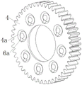
FIG. 3 is an end view of the first planet;
fig. 4 is a schematic diagram of the engagement of the first planet wheel with the second planet wheel;
FIG. 5 is a schematic diagram of the position identification of the cylindrical ring groove;
FIG. 6 is a schematic view of a double cycloid planetary transmission meshing line with small tooth difference;
FIG. 7 is a schematic view of the engagement initiation point of FIG. 6;
FIG. 8 is a schematic view of the engagement termination point of FIG. 6;
FIG. 9 is a comparison graph of a double cycloid gear tooth profile and an involute tooth profile with the same parameters;
fig. 10 is a perspective sectional view of fig. 2.
Fig. 11 is an exploded view of fig. 10.
Reference numerals:
the device comprises a box body 1, a double-eccentric input shaft 2, an internal gear 3, a first planet gear 4, a second planet gear 5, a cylindrical ring groove constant speed mechanism 6, an output flange 7 and a cylindrical rolling body 6 a;
the box body comprises a box body middle section 1a, a left end cover 1b, a right end cover 1c, an O-shaped sealing ring 1d, an O-shaped sealing ring 1e, a screw 1f and a screw 1 g;
a flat key 2a, a lip-shaped sealing ring 2b, a lip-shaped sealing ring 2c, an angular contact ball bearing 2d, an angular contact ball bearing 2e, a first eccentric shaft sleeve 2f, a second eccentric shaft sleeve 2g, a flat key 2h, a flat key 2i, a rotary arm bearing 2j and a rotary arm bearing 2 k;
a cylindrical ring groove I4 a; a cylindrical ring groove II 5a and a cylindrical ring groove III 5 b;
the angular contact ball bearing 7a, the lip seal ring 7b, the threaded hole 7c and the cylindrical annular groove IV 7 d.
Detailed Description
The embodiments of the present invention are described below with reference to specific embodiments, and other advantages and effects of the present invention will be easily understood by those skilled in the art from the disclosure of the present specification. The invention is capable of other and different embodiments and of being practiced or of being carried out in various ways, and its several details are capable of modification in various respects, all without departing from the spirit and scope of the present invention. It should be noted that the drawings provided in the following embodiments are only for illustrating the basic idea of the present invention in a schematic way, and the features in the following embodiments and examples may be combined with each other without conflict.
Wherein the showings are for the purpose of illustrating the invention only and not for the purpose of limiting the same, and in which there is shown by way of illustration only and not in the drawings in which there is no intention to limit the invention thereto; to better illustrate the embodiments of the present invention, some parts of the drawings may be omitted, enlarged or reduced, and do not represent the size of an actual product; it will be understood by those skilled in the art that certain well-known structures in the drawings and descriptions thereof may be omitted.
The same or similar reference numerals in the drawings of the embodiments of the present invention correspond to the same or similar components; in the description of the present invention, it should be understood that if there is an orientation or positional relationship indicated by terms such as "upper", "lower", "left", "right", "front", "rear", etc., based on the orientation or positional relationship shown in the drawings, it is only for convenience of description and simplification of description, but it is not an indication or suggestion that the referred device or element must have a specific orientation, be constructed in a specific orientation, and be operated, and therefore, the terms describing the positional relationship in the drawings are only used for illustrative purposes, and are not to be construed as limiting the present invention, and the specific meaning of the terms may be understood by those skilled in the art according to specific situations.
A cylindrical ring groove type double cycloid planetary reducer with small tooth difference is shown in a structural schematic diagram of fig. 1. The speed reducer comprises a box body 1 used for fixing the speed reducer, a double-eccentric input shaft 2 connected with a high-speed part, two planetary wheels (correspondingly marked as a first planetary wheel 4 and a second planetary wheel 5) which do eccentric motion and are completely the same, an inner gear 3 meshed with the two planetary wheels, and an output flange 7 connected with a low-speed part. An assembly drawing of the cylindrical ring groove type double cycloid planetary reducer with small tooth difference is shown in figure 2.
In the present embodiment, the (reduction gear) case 1 includes three parts in total: the box body comprises a middle box body section 1a, a left end cover 1b and a right end cover 1 c. The middle section 1a of the box body is provided with a through hole for fixing the speed reducer; the internal gear 3 is fixed on the middle section of the box body. The left end cover 1b and the right end cover 1c are correspondingly arranged at the left side end face and the right side end face of the box body middle section 1a, the joint face of the left end cover 1b and the box body middle section 1a and the joint face of the right end cover 1c and the box body middle section 1a are respectively provided with an O-shaped sealing ring 1d and an O-shaped sealing ring 1e, and the left end cover 1b and the right end cover 1c are respectively connected with the box body middle section 1a through screws 1f and 1 g.
In the present embodiment, the double-eccentric input shaft 2 includes 6 circular shaft segments, and the first shaft segment, the second shaft segment, the third shaft segment, the fourth shaft segment, the fifth shaft segment and the sixth shaft segment are sequentially arranged from left to right with reference to the direction shown in fig. 2. The double eccentric input shaft 2 is double eccentric by two eccentric sleeves. Specifically, the third shaft section and the fifth shaft section are respectively provided with an eccentric shaft sleeve which is respectively called as a first eccentric shaft sleeve 2f and a second eccentric shaft sleeve 2g, and the first eccentric shaft sleeve 2f and the second eccentric shaft sleeve 2g have the same eccentric amount relative to the central axis of the double-eccentric input shaft 2 and are distributed in an angle of 180 degrees; the first eccentric shaft sleeve 2f is connected to the third shaft section through a flat key 2h to form a first eccentric section, and the second eccentric shaft sleeve 2g is connected to the fifth shaft section through a flat key 2i to form a second eccentric section; and the first planet gear 4 is mounted on the first eccentric sleeve 2f through a rocker bearing 2j, and the second planet gear 5 is mounted on the second eccentric sleeve 2g through a rocker bearing 2 k. The movement and power of the high speed member are inputted through a flat key 2a provided on the first shaft section. Lip-shaped sealing rings 2b and 2c for sealing are respectively arranged on the second shaft section and the sixth shaft section. Angular contact ball bearings 2d and 2e are also mounted on the third shaft segment and the fifth shaft segment, respectively (the angular contact ball bearings 2d and 2e are not mounted on the eccentric sleeve), and respectively support the double-eccentric input shaft 2 on the left end cover 1b and the output flange 7 of the box body. The fourth shaft section is a positioning shoulder for axially positioning the rocker bearings 2j and 2k and the eccentric bushes 2f and 2 g.
In the present embodiment, the first planetary gear 4 is supported on the first eccentric sleeve 2f by the rocker bearing 2j, and a plurality of cylindrical ring grooves i 4a are formed on the right end surface of the first planetary gear 4, and the cylindrical ring grooves i are uniformly distributed along the central axis of the first planetary gear 4 (as shown in fig. 3).
In this embodiment, the second planet wheel 5 is supported on the second eccentric sleeve 2g through a rotating arm bearing 2k, a plurality of cylindrical ring grooves ii 5a are processed on the left end face of the second planet wheel 5, and a plurality of cylindrical ring grooves iii 5b are processed on the right end face of the second planet wheel 5, and the cylindrical ring grooves ii and the cylindrical ring grooves iii are uniformly distributed along the central axis of the second planet wheel 5.
In this embodiment, the output flange 7 is supported on the right end cover 1c of the box body through an angular contact ball bearing 7a, a lip-shaped sealing ring 7b for sealing is arranged between the output flange 7 and the right end cover 1c of the box body, a plurality of threaded holes 7c uniformly distributed along the central axis of the output flange 7 are further formed in the right end face of the output flange 7 and used for being connected with a low-speed part, a plurality of cylindrical annular grooves iv 7d are machined in the left end face of the output flange, and the cylindrical annular grooves iv are uniformly distributed along the central axis of the input flange 7. The cylindrical ring grooves I4 a, the cylindrical ring grooves II 5a, the cylindrical ring grooves III 5b and the cylindrical ring grooves IV 7d which are correspondingly arranged on the four end faces are the same in quantity.
The cylindrical ring groove I4 a, the cylindrical ring groove II 5a, the cylindrical ring groove III 5b and the cylindrical ring groove IV 7d are all of the same structure (i.e., an annular groove with a v-shaped section). Wherein, the (radius) size of the cylindrical ring groove I4 a of setting on the 4 right side terminal surface of first planet wheel is the same with the cylindrical ring groove II 5a of setting on the 5 left side terminal surface of second planet wheel, and after first planet wheel 4 and second planet wheel 5 installed in place, cylindrical ring groove I4 a and cylindrical ring groove II 5a on its terminal surface formed the relation that the one-to-one matches, and correspond again between each assorted cylindrical ring groove I4 a and cylindrical ring groove II 5a and be equipped with the cylinder rolling element 6a that can roll around this ring groove axis. The description will be given by taking the cylindrical ring groove I4 a and the cylindrical ring groove II 5a which are matched with each other as an example: the cylindrical ring groove I4 a and the cylindrical ring groove II 5a are both inwards concave V-shaped grooves which are encircled to form an annular structure, the cylindrical rolling body 6a is of a cylindrical structure, and after the two grooves are correspondingly matched, the cylindrical rolling body 6a is obliquely arranged in the two ring grooves and can roll in the ring grooves, as shown in figure 4.
Similarly, the cylindrical ring groove iii 5b on the right end face of the second planet wheel 5 and the cylindrical ring groove iv 7d on the left end face of the output flange 7 have the same (radius) size, and after the second planet wheel 5 and the output flange 7 are mounted in place, the cylindrical ring grooves iii 5b on the end faces and the cylindrical ring grooves iv 7d form a one-to-one matching relationship, and cylindrical rolling bodies 6a capable of rolling around the axis of the ring grooves are correspondingly arranged between the matched cylindrical ring grooves iii 5b and the cylindrical ring grooves iv 7 d.
In order to ensure reliable rolling fit of the cylindrical ring groove I4 a, the cylindrical ring groove II 5a, the cylindrical ring groove III 5b and the cylindrical ring groove IV 7d with the cylindrical rolling bodies in between, the positions of the ring grooves need to be controlled specially. Specifically, the diameter phi 1 of a distribution circle where the central axis of each cylindrical ring groove I is located, the diameter phi 2 of a distribution circle where the central axis of each cylindrical ring groove II is located, the diameter phi 3 of a distribution circle where the central axis of each cylindrical ring groove III is located, and the diameter phi 4 of a distribution circle where the central axis of each cylindrical ring groove IV is located are the same; the radius b1 of the cylindrical ring groove III is half of the radius b2 of the cylindrical ring groove II, which is distinguished from the formula and is marked by a letter b. (as shown in fig. 5).
If the eccentric amounts of the first eccentric sleeve 2f and the second eccentric sleeve 2g with respect to the central axis of the double eccentric input shaft 2 are e, the geometric center distance between the cylindrical ring groove i 4a and the cylindrical ring groove ii 5a is 2e, and the geometric center distance between the cylindrical ring groove iii 5b and the cylindrical ring groove iv 7d is e. The cylindrical ring grooves I4 a and II 5a, and the cylindrical ring grooves III 5b and IV 7d are arranged in one-to-one correspondence, and the cylindrical ring grooves I4 a, II 5a, III 5b and IV 7d satisfy the above-mentioned size and position relationship, so that the geometric centers of the cylindrical rolling bodies 6a (obliquely) embedded on the two end faces of the second planet wheel 5 can be connected into a parallelogram structure, as shown by the thin-dot-dash line in FIG. 1, so that the cylindrical ring grooves 4a, 5b, 7d and the cylindrical rolling bodies jointly form a parallelogram constant-speed transmission mechanism, namely the cylindrical ring groove constant-speed mechanism 6.
In the present embodiment, taking the first planetary gear 4 and the internal gear 3 as an example, the double cycloid small-difference planetary gear meshing line is as shown in fig. 6, 7, and 8. The first planet-wheel 4 is centred at O1Point, center in 3 of internal gear is located at O2Point, meshing line is a circular arc with radius R, and the center of meshing line is positioned at O3Point, point O1、O2、O3Are positioned on the same straight line; the first planet wheel 4 has a pitch circle diameter r1The diameter of the addendum circle is ra1(ii) a The pitch circle diameter of the internal gear 3 is r2The diameter of the addendum circle is ra2(ii) a The starting point P of the meshing line is the intersection point of pitch circles of the two gears, the meshing end point B is the intersection point of addendum circles of the two gears, and the central angle corresponding to the starting point and the end point of the meshing line is beta. In the whole meshing period, the first planet wheel 4 and the inner gear 3 are both in tooth top-to-tooth contact, and the tooth roots of the two gears are not in tooth root contactAnd (4) participating in meshing, wherein a meshing line is a circular arc.
In this embodiment, the tooth profile curves of the first planet gear 4 and the second planet gear 5 are the same, and the tooth profiles of the two planet gears and the inner gear 3 are both formed by combining an epicycloid and a hypocycloid, the difference is that the tooth-addendum tooth profile of the first planet gear 4 and the tooth-addendum tooth profile of the second planet gear 5 are an epicycloid, the tooth-dedendum tooth profile of the inner gear 3 is a hypocycloid, and the tooth-dedendum tooth profile is an epicycloid. Taking the tooth profile of the first planet gear 4 as an example, the pair of the double cycloid tooth profile and the involute tooth profile with the same parameter is shown in fig. 9. The top part of the double cycloid tooth profile tooth top is obviously wider than the involute gear with the same parameter, although the tooth root part is narrower than the involute gear with the same parameter, the contact ratio of double cycloid few-tooth-difference planetary transmission is larger, the load borne by a single tooth is reduced, and the bearing capacity of the speed reducer is improved. In addition, as the diameters of rolling circles formed by the hypocycloids and the epicycloids in the double-cycloid tooth profiles are different, singular points exist at the connecting positions of the hypocycloids and the epicycloids, but the tooth crests are contacted with the tooth crests in the meshing process, and the singular points are the starting points of the meshing areas, so that the singular points cannot influence the normal meshing of the gears; meanwhile, the inner cycloid and the outer cycloid are in convex contact all the time in the meshing process, so that the sliding rate is extremely low, the transmission efficiency of the speed reducer is improved, and the precision attenuation of the speed reducer is slowed down.
The working process of the cylindrical ring groove type double cycloid planetary reducer with small tooth difference comprises the following steps: high-speed piece passes through the parallel key with motion and power transmission for two eccentric input shaft 2, two eccentric input shaft 2 again respectively through parallel key 2h and 2i drive first eccentric axle sleeve 2f and second eccentric axle sleeve 2g rotate, thereby give first planet wheel 4 and second planet wheel 5 motion and power transmission, two planet wheel synchronous rotation are guaranteed to cylinder annular constant velocity mechanism 6, transmit the motion and the power of two planet wheels for output flange 7 simultaneously, transmit the low-speed piece for by output flange 7 again, realize slowing down and increase torsion.
Hereinafter, the contact ratio of the speed reducer will be described in addition by taking a speed reducer in which different gear parameters are matched as an example.
For a single planetary gear-internal gear meshing pair, when the tooth number z1 of the planetary gear is 36, the tooth number z2 of the internal gear is 52, the modulus m is 3mm, and the tooth crest coefficient is high When the planet wheel-internal gear meshing pair is in a single pair, the contact ratio of the planet wheel-internal gear meshing pair is calculated to be 4.886; when z 1-80, z 2-84, m-3,
 when the planet wheel-internal gear meshing pair is in a single pair, the contact ratio of the planet wheel-internal gear meshing pair is calculated to be 20.3106; when z1 is 79, z2 is 80, m is 3,
 the contact ratio of a single pair of planet wheel-internal gear meshing pairs is calculated to be 38; therefore, when the tooth number difference is different, the transmission with large contact ratio can be realized; compared with the RV reducer, the simultaneous contact tooth number of the planetary reducer can be close to half of the total tooth number of the planet wheel, the high-precision assembly of pin teeth in the RV reducer is avoided, the number of parts is reduced, and the processing and mounting difficulty of the reducer is reduced; compared with a harmonic reducer, the transmission of motion and power by utilizing the elastic deformation of a thin-wall part is avoided, the service life is longer, and the torsional rigidity is higher; compared with involute few-tooth-difference planetary transmission, double-cycloid few-tooth-difference planetary transmission is not easy to interfere, and complex tooth profile design is avoided.
Finally, the above embodiments are only intended to illustrate the technical solutions of the present invention and not to limit the present invention, and although the present invention has been described in detail with reference to the preferred embodiments, it will be understood by those skilled in the art that modifications or equivalent substitutions may be made on the technical solutions of the present invention without departing from the spirit and scope of the technical solutions, and all of them should be covered by the claims of the present invention.
Claims (6)
1. The utility model provides a little poor planetary reducer of tooth of cylinder ring slot type double cycloid which characterized in that: the double-eccentric planetary gear set comprises a double-eccentric input shaft, two identical planetary gears, an inner gear and an output flange, wherein the two planetary gears are a first planetary gear and a second planetary gear respectively;
the double-eccentric input shaft is provided with a first eccentric section and a second eccentric section, the first eccentric section and the second eccentric section are distributed at an angle of 180 degrees relative to the central axis of the double-eccentric input shaft, and the eccentric amounts of the two eccentric sections are the same;
the first planet wheel is correspondingly sleeved on the first eccentric section through a rotary arm bearing, and the second planet wheel is correspondingly sleeved on the second eccentric section through a rotary arm bearing; the first planet wheel and the second planet wheel are meshed with the internal gear; the output flange is arranged on the double-eccentric input shaft through an angular contact ball bearing, the first planet wheel is arranged on the left end face of the second planet wheel, and the output flange is correspondingly arranged on the right end face of the second planet wheel;
a plurality of cylindrical ring grooves I are uniformly distributed on the right end face of the first planet wheel around the central axis of the first planet wheel, a plurality of cylindrical ring grooves II are uniformly distributed on the left end face of the second planet wheel around the central axis of the second planet wheel, the cylindrical ring grooves I and the cylindrical ring grooves II have the same size and are matched in a one-to-one correspondence manner, and cylindrical rolling bodies capable of rolling around the axis of the ring grooves are correspondingly arranged between the matched cylindrical ring grooves I and the cylindrical ring grooves II;
a plurality of cylindrical ring grooves III are uniformly distributed on the right end face of the second planet wheel around the central axis of the second planet wheel, a plurality of cylindrical ring grooves IV are uniformly distributed on the left end face of the output flange around the central axis of the second planet wheel, the cylindrical ring grooves III are the same as and matched with the cylindrical ring grooves IV in size in a one-to-one correspondence manner, and cylindrical rolling bodies capable of rolling around the axis of the ring grooves are correspondingly arranged between the matched cylindrical ring grooves III and the cylindrical ring grooves IV;
the diameter phi 1 of a distribution circle where the central axis of each cylindrical ring groove I is located, the diameter phi 2 of a distribution circle where the central axis of each cylindrical ring groove II is located, the diameter phi 3 of a distribution circle where the central axis of each cylindrical ring groove III is located, and the diameter phi 4 of a distribution circle where the central axis of each cylindrical ring groove IV is located are the same; wherein the radius of the cylindrical ring groove III is half of that of the cylindrical ring groove II.
2. The cylindrical ring groove type double cycloid planetary reducer with small tooth difference as claimed in claim 1, wherein: the tooth profiles of the planet wheel and the inner gear are both formed by combining an epicycloid and a hypocycloid; the tooth top tooth profile of the planet gear is an epicycloid, the tooth bottom tooth profile of the planet gear is a hypocycloid, the tooth top tooth profile of the internal gear is a hypocycloid, and the tooth bottom tooth profile of the internal gear is an epicycloid.
3. The cylindrical ring groove type double cycloid planetary reducer with small tooth difference as claimed in claim 2, characterized in that: in a meshing period, the two planet wheels and the inner gear are always meshed with each other through tooth tops, a meshing line is an arc curve, and tooth root parts of the two planet wheels and the inner gear do not participate in meshing.
4. The cylindrical ring groove type double cycloid small tooth difference planetary reducer as claimed in claim 3, characterized in that:
the tooth profile of the tooth crest of the planet wheel is a rolling circle with the radius of R and the radius of R1The pitch circle of the planet wheel is inscribed in the outer roll to form an overcenter epicycloid, and the tooth profile equation is as follows:

the tooth top tooth profile of the internal gear is a rolling circle with the radius of R and the radius of R2The inner gear pitch circle internally tangent inner rolling forms an inner cycloidal with a core, and the tooth profile equation is as follows:

in the formula:
xa1/ya1a point on the tooth top profile of the planet gear is in the coordinate system X1O1Y1Abscissa/ordinate of (1);
xa2/ya2a point on the tooth top profile of the internal gear is in the coordinate system X2O2Y2Abscissa/ordinate of (1);
r1/r2pitch radius of planet wheel/internal gear, r1=mz1/2,r2=mz2/2 wherein z1、z2The number of teeth of the planet gear and the inner gear is respectively, and m is the gear module;
r-radius of the circle on which the meshing line is located, and:

t-angle variables for generating the tooth profile of the planet wheel/internal gear, and:

wherein:


5. The cylindrical ring groove type double cycloid small tooth difference planetary reducer of claim 4, wherein:
the tooth root tooth profile of the planet gear is formed by the tooth top tooth profile of the inner gear in a conjugate mode, and meanwhile, in order to avoid multipoint contact, the tooth root tooth profile of the planet gear is equivalently converted into a tooth root tooth profile with the radius r according to the cycloid forming relation2R has a rounding and a radius of R2The inner gear pitch circle internally tangent inner roll forms a non-enveloping long-amplitude hypocycloid, and the tooth profile equation is as follows:

the tooth root tooth profile of the inner gear is formed by the tooth top tooth profile of the planet gear in a conjugate mode; meanwhile, in order to avoid multi-point contact, the tooth root tooth profile of the internal gear is equivalently converted into the radius R-R according to the cycloid forming relation1Has a rounding radius of r1The planetary gear pitch circle circumscribed external rolling forms a non-enveloping long-amplitude epicycloid, and the tooth profile equation is as follows:

in the formula:
xf1/yf1-a point on the tooth-root profile of the planet gear is in the coordinate system X1O1Y1Abscissa/ordinate of (1);
xf2/yf2-a point on the tooth-root profile of the internal gear wheel in the coordinate system X2O2Y2Abscissa/ordinate of (1);
λ1/λ2and the tooth root tooth profile length and width coefficient of the planet wheel/internal gear.
6. The cylindrical ring groove type double cycloid small tooth difference planetary reducer of claim 4, wherein: the engaging-in and engaging-out limit positions of the single-pair planet wheel-inner gear engaging pair are respectively a pitch circle intersection point and an addendum circle intersection point, and the contact ratio calculation formula is as follows:

Priority Applications (1)
| Application Number | Priority Date | Filing Date | Title |
|---|---|---|---|
| CN202110018201.4A CN112780728B (en) | 2021-01-07 | 2021-01-07 | Cylindrical ring groove type double cycloid small tooth difference planetary reducer |
Applications Claiming Priority (1)
| Application Number | Priority Date | Filing Date | Title |
|---|---|---|---|
| CN202110018201.4A CN112780728B (en) | 2021-01-07 | 2021-01-07 | Cylindrical ring groove type double cycloid small tooth difference planetary reducer |
Publications (2)
| Publication Number | Publication Date |
|---|---|
| CN112780728A CN112780728A (en) | 2021-05-11 |
| CN112780728B true CN112780728B (en) | 2022-05-17 |
Family
ID=75756686
Family Applications (1)
| Application Number | Title | Priority Date | Filing Date |
|---|---|---|---|
| CN202110018201.4A Active CN112780728B (en) | 2021-01-07 | 2021-01-07 | Cylindrical ring groove type double cycloid small tooth difference planetary reducer |
Country Status (1)
| Country | Link |
|---|---|
| CN (1) | CN112780728B (en) |
Families Citing this family (1)
| Publication number | Priority date | Publication date | Assignee | Title |
|---|---|---|---|---|
| CN113339471A (en) * | 2021-06-23 | 2021-09-03 | 江苏理工学院 | Cosine internal tooth profile small tooth difference planetary reducer of steel ball ring groove transmission structure |
Citations (12)
| Publication number | Priority date | Publication date | Assignee | Title |
|---|---|---|---|---|
| WO1996017187A1 (en) * | 1994-11-29 | 1996-06-06 | Scandrive I Hallstahammar Ab | Eccentric gear |
| JP2005186667A (en) * | 2003-12-24 | 2005-07-14 | Ntn Corp | Electrically driven wheel driving device |
| JP2007205450A (en) * | 2006-02-01 | 2007-08-16 | Mitsubishi Heavy Ind Ltd | Structure of reduction gear |
| JP2012251595A (en) * | 2011-06-02 | 2012-12-20 | Sumitomo Heavy Ind Ltd | Reduction gear device of wind power generating facility |
| JP2014145433A (en) * | 2013-01-29 | 2014-08-14 | Sumitomo Heavy Ind Ltd | Series of eccentric oscillation type reduction gears |
| CN103994184A (en) * | 2014-03-26 | 2014-08-20 | 重庆大学 | Closed cycloid precision gear reducer |
| CN107299970A (en) * | 2017-08-17 | 2017-10-27 | 安徽捷线传动科技有限公司 | A kind of cycloidal ball deceleration device and its application in joint of robot |
| TW201819797A (en) * | 2016-11-16 | 2018-06-01 | 柯重成 | Precision cycloid device |
| CN110195767A (en) * | 2019-05-12 | 2019-09-03 | 天津大学 | A kind of closed hypocycloid movable teeth reducer |
| JP2019158144A (en) * | 2018-03-08 | 2019-09-19 | ナブテスコ株式会社 | Transmission device |
| CN111765213A (en) * | 2020-06-22 | 2020-10-13 | 苏州华震工业机器人减速器有限公司 | Industrial robot inner gearing RV speed reducer |
| CN112065950A (en) * | 2020-02-11 | 2020-12-11 | 李瑞德 | High-contact-ratio internal gear and RV speed reducer taking same as transmission core |
Family Cites Families (6)
| Publication number | Priority date | Publication date | Assignee | Title |
|---|---|---|---|---|
| JP2003278849A (en) * | 2002-03-27 | 2003-10-02 | Sumitomo Heavy Ind Ltd | Reduction gear and series thereof |
| TWI223034B (en) * | 2002-08-30 | 2004-11-01 | Sumitomo Heavy Industries | Power transmission device |
| JP4947884B2 (en) * | 2004-08-20 | 2012-06-06 | 住友重機械工業株式会社 | Method for manufacturing pin of planetary rotating member of planetary reduction mechanism |
| US7749123B2 (en) * | 2007-02-06 | 2010-07-06 | Gm Global Technology Operations, Inc. | Cycloid limited slip differential and method |
| CN104373542A (en) * | 2014-10-24 | 2015-02-25 | 浙江恒丰泰减速机制造有限公司 | Locating transmission mechanism |
| BG67342B1 (en) * | 2018-07-11 | 2021-06-15 | Георгиев Василев Явор | Friction planetary drive with permanent gear-reduction ratio |
-
2021
- 2021-01-07 CN CN202110018201.4A patent/CN112780728B/en active Active
Patent Citations (12)
| Publication number | Priority date | Publication date | Assignee | Title |
|---|---|---|---|---|
| WO1996017187A1 (en) * | 1994-11-29 | 1996-06-06 | Scandrive I Hallstahammar Ab | Eccentric gear |
| JP2005186667A (en) * | 2003-12-24 | 2005-07-14 | Ntn Corp | Electrically driven wheel driving device |
| JP2007205450A (en) * | 2006-02-01 | 2007-08-16 | Mitsubishi Heavy Ind Ltd | Structure of reduction gear |
| JP2012251595A (en) * | 2011-06-02 | 2012-12-20 | Sumitomo Heavy Ind Ltd | Reduction gear device of wind power generating facility |
| JP2014145433A (en) * | 2013-01-29 | 2014-08-14 | Sumitomo Heavy Ind Ltd | Series of eccentric oscillation type reduction gears |
| CN103994184A (en) * | 2014-03-26 | 2014-08-20 | 重庆大学 | Closed cycloid precision gear reducer |
| TW201819797A (en) * | 2016-11-16 | 2018-06-01 | 柯重成 | Precision cycloid device |
| CN107299970A (en) * | 2017-08-17 | 2017-10-27 | 安徽捷线传动科技有限公司 | A kind of cycloidal ball deceleration device and its application in joint of robot |
| JP2019158144A (en) * | 2018-03-08 | 2019-09-19 | ナブテスコ株式会社 | Transmission device |
| CN110195767A (en) * | 2019-05-12 | 2019-09-03 | 天津大学 | A kind of closed hypocycloid movable teeth reducer |
| CN112065950A (en) * | 2020-02-11 | 2020-12-11 | 李瑞德 | High-contact-ratio internal gear and RV speed reducer taking same as transmission core |
| CN111765213A (en) * | 2020-06-22 | 2020-10-13 | 苏州华震工业机器人减速器有限公司 | Industrial robot inner gearing RV speed reducer |
Non-Patent Citations (3)
| Title |
|---|
| Numerical exploration on jet oscillation mechanism of counterflowing jet ahead of a hypersonic lifting-body vehicle;DENG Fan等;《Science China(Technological Sciences)》;20180701(第07期);第112~127页 * |
| 基于K-H-V-S组合机构直线传动器的研究;李思益;《嘉兴学院学报》;20111101(第06期);第111~113、143页 * |
| 浮动盘式摆线二次包络行星传动实验研究;陈兵奎等;《机械传动》;20101015(第10期);第4~7页 * |
Also Published As
| Publication number | Publication date |
|---|---|
| CN112780728A (en) | 2021-05-11 |
Similar Documents
| Publication | Publication Date | Title |
|---|---|---|
| US10948048B2 (en) | Thickness-variable transmission structure for robot joint | |
| EP0286760A1 (en) | Cycloidal equidistant curved gear transmission mechanism and its device | |
| CN108679167B (en) | Planetary line gear reducer with small tooth difference | |
| WO2020015590A1 (en) | Planetary reduction electrical machine capable of achieving full closed-loop control and articulated robot | |
| CN110630720B (en) | Cycloidal-like gear reducer | |
| JP7466255B2 (en) | Gear Pair and Nutation Reducer | |
| CN112780728B (en) | Cylindrical ring groove type double cycloid small tooth difference planetary reducer | |
| US4016780A (en) | Hypotrochoidal cluster gear drives | |
| CN111637193B (en) | Inner gearing helical gear transmission mechanism | |
| CN112065950A (en) | High-contact-ratio internal gear and RV speed reducer taking same as transmission core | |
| CN110802422B (en) | Non-return difference machine tool rotary table | |
| CN111853168B (en) | Built-in planetary gear reducer | |
| CN111637200A (en) | Helical gear planetary transmission mechanism | |
| CN212455376U (en) | Built-in planetary gear reducer | |
| CN108044645B (en) | Variable-thickness robot joint transmission structure | |
| CN211501500U (en) | Differential cycloidal pin gear speed changing device | |
| CN216078162U (en) | Off-axis simple two-gear speed change mechanism | |
| CN214661789U (en) | RV reducer adopting herringbone gear planetary reduction mechanism | |
| CN108533683A (en) | Convex-convex engagement pure rolling spiral bevel gear mechanism for intersecting axle transmission | |
| CN210153157U (en) | Double-arc planetary transmission device with small tooth difference and meshed with gaps | |
| CN208634292U (en) | A kind of planetary reducer | |
| CN109139812A (en) | A kind of New-type cycloidal planetary reducer | |
| CN220956713U (en) | High-rigidity low-return-difference speed reducer for small robot | |
| CN108533685A (en) | Male-female engagement pure rolling spiral bevel gear mechanism for intersecting axle transmission | |
| CN211501499U (en) | Differential cycloidal gear speed change device |
Legal Events
| Date | Code | Title | Description |
|---|---|---|---|
| PB01 | Publication | ||
| PB01 | Publication | ||
| SE01 | Entry into force of request for substantive examination | ||
| SE01 | Entry into force of request for substantive examination | ||
| GR01 | Patent grant | ||
| GR01 | Patent grant |