CN112768820B - Container energy storage system - Google Patents
Container energy storage system Download PDFInfo
- Publication number
- CN112768820B CN112768820B CN202011279711.9A CN202011279711A CN112768820B CN 112768820 B CN112768820 B CN 112768820B CN 202011279711 A CN202011279711 A CN 202011279711A CN 112768820 B CN112768820 B CN 112768820B
- Authority
- CN
- China
- Prior art keywords
- battery
- box
- energy storage
- storage system
- plug
- Prior art date
- Legal status (The legal status is an assumption and is not a legal conclusion. Google has not performed a legal analysis and makes no representation as to the accuracy of the status listed.)
- Active
Links
Images


Classifications
-
- Y—GENERAL TAGGING OF NEW TECHNOLOGICAL DEVELOPMENTS; GENERAL TAGGING OF CROSS-SECTIONAL TECHNOLOGIES SPANNING OVER SEVERAL SECTIONS OF THE IPC; TECHNICAL SUBJECTS COVERED BY FORMER USPC CROSS-REFERENCE ART COLLECTIONS [XRACs] AND DIGESTS
- Y02—TECHNOLOGIES OR APPLICATIONS FOR MITIGATION OR ADAPTATION AGAINST CLIMATE CHANGE
- Y02E—REDUCTION OF GREENHOUSE GAS [GHG] EMISSIONS, RELATED TO ENERGY GENERATION, TRANSMISSION OR DISTRIBUTION
- Y02E60/00—Enabling technologies; Technologies with a potential or indirect contribution to GHG emissions mitigation
- Y02E60/10—Energy storage using batteries
Landscapes
- Battery Mounting, Suspending (AREA)
Abstract
The invention relates to a container energy storage system. The container energy storage system comprises a container and a battery inserting box; the battery subrack includes: the battery rack is arranged in a plurality of layers in the vertical direction to form a module mounting layer which is stacked up and down, and the battery modules are loaded in the module mounting layer in a layered manner; the travelling wheels are arranged at the bottom of the battery rack and are used for moving the battery inserting box; the sealing plates are arranged on the periphery of the battery rack and used for enclosing a sealed battery module accommodating space; the plug-in box connector is arranged on one side of the battery plug-in box in the horizontal direction and is used for being plugged with an adaptive connector in the container energy storage system when the battery plug-in box moves by means of the travelling wheels so as to supply power; be equipped with the subrack track in the container for the walking wheel to the battery subrack leads to be connected with the adapter connector in the container energy storage system with the subrack connector on the guide battery subrack. Above-mentioned scheme has solved among the current container energy storage system problem that the space is nervous, dismouting maintain inconvenient.
Description
Technical Field
The invention relates to a container energy storage system.
Background
Along with the wide use widely of energy storage system, the energy density and the power density of the battery box for energy storage system are constantly promoting, and the use quantity of battery box is also more and more. The energy storage system includes a large number of batteries, and generally, a certain number of battery cells form a battery module, a certain number of battery modules form a battery box, and then a certain number of battery boxes are stacked to form an energy storage system.
The conventional energy storage system is generally in a container type, a battery cabinet is arranged in the container, a plurality of battery cabinet accommodating spaces are arranged on the battery cabinet in an array form, and the battery cabinet accommodating spaces are used for accommodating battery cabinets, for example, an energy storage battery cabinet disclosed in chinese patent publication No. CN 105129269A.
However, the battery boxes in the existing energy storage system are arranged in an up-and-down stacking manner, the battery boxes need to be transferred to corresponding positions in the container from the container opening by using the trolley and pushed into corresponding battery box accommodating spaces in the battery cabinet, so that a large transfer space is required in the container for the trolley to walk, and the battery boxes need to be operated by using a large space, which not only affects the energy density of the energy storage system, but also needs more operators for loading and unloading the battery modules, and is inconvenient to disassemble, assemble and maintain.
Disclosure of Invention
The invention aims to provide a container energy storage system, which solves the problems of lack of space and inconvenient disassembly and assembly and maintenance in the conventional container energy storage system.
The invention adopts the following technical scheme:
the container energy storage system comprises a container and a battery inserting box;
the battery subrack includes:
the battery rack is arranged in multiple layers in the vertical direction to form a module mounting layer which is stacked up and down, and a battery module is arranged in layers and consists of a battery cell and a battery cell retainer;
the travelling wheels are arranged at the bottom of the battery rack and are used for moving the battery inserting box;
the seal plates are arranged on the periphery of the battery rack and used for enclosing a sealed battery module accommodating space;
the plug-in box connector is arranged on one side of the battery plug-in box in the horizontal direction and is used for being plugged with an adaptive connector in the container energy storage system when the battery plug-in box moves by virtue of the travelling wheels so as to realize power supply;
and an inserting box track is arranged in the container and used for guiding the travelling wheels of the battery inserting box to guide an inserting box connector on the battery inserting box to be connected with an adaptive connector in the container energy storage system.
Has the advantages that: by adopting the technical scheme, the battery frame of the battery plug-in box forms a plurality of layers of module mounting layers, and a closed battery module accommodating space can be enclosed by the sealing plates to form an integral battery box, so that modularization can be realized, and the mounting requirements of a large number of battery modules can be met; meanwhile, the travelling wheels at the bottom of the battery frame are relied on, so that the whole battery plug box becomes a battery box capable of moving automatically, the loading and unloading operation of the independent battery box is not required to be carried out in the container by virtue of a trolley, the operation space requirement is small, the improvement of energy density is facilitated, the battery plug box can be moved in place by pushing and pulling the whole battery plug box, the plug box connector is separated from or plugged into the adaptive connector, and the disassembly and the maintenance are convenient.
As a preferred technical scheme: the plug box connector comprises a positive connector and a negative connector, and the two plug box connectors are respectively arranged at the top and the bottom of the battery plug box.
Has the beneficial effects that: by adopting the technical scheme, the vertical balance of the plugging force can be ensured, so that the plugging reliability can be improved.
As a preferred technical scheme: the battery subrack further comprises:
and the module connecting row is used for connecting the battery modules in the corresponding two layers of module mounting layers.
Has the beneficial effects that: the module connecting row can reduce the use of cables, is convenient to connect and has good reliability.
As a preferred technical scheme: the sealing plates comprise a front sealing plate, a rear sealing plate, a left sealing plate and a right sealing plate, the inserting box connector is arranged on the rear sealing plate, and the front sealing plate is provided with a battery management unit;
the battery subrack further comprises a heat conduction cushion layer, the heat conduction cushion layer is used for being arranged between the battery module and the left side sealing plate and between the battery module and the right side sealing plate, and the battery module and the corresponding sealing plates are tightly attached to the heat conduction cushion layer at the same time.
Has the beneficial effects that: by adopting the technical scheme, the operation and the information acquisition are convenient, the heat dissipation of the battery module is convenient, and the heat dissipation problem of the modularized battery plug box is solved.
As a preferred technical scheme: the heat conduction cushion layer is bonded on the exposed electric core of the battery module.
Has the beneficial effects that: adopt above-mentioned technical scheme to be convenient for carry out the dismouting, the operation is convenient to the shrouding.
As a preferred technical scheme: left side shrouding and right side shrouding are the PCI heat conduction material for the heat of balanced battery module.
Has the advantages that: by adopting the technical scheme, better temperature equalization performance can be obtained.
As a preferred technical scheme: and the left sealing plate and the right sealing plate are detachably fixed on the battery rack.
Has the beneficial effects that: adopt above-mentioned technical scheme to be convenient for load and unload and maintain the battery module.
As a preferred technical scheme: and fuses are fixed in the battery rack and are connected in series with corresponding plug box connectors.
Has the beneficial effects that: by adopting the technical scheme, the reliability and the safety of the system are improved.
As a preferred technical scheme: the subrack connector is a drawer type connector, and the drawer type connector comprises:
a housing for securing to a closure plate of the battery holder;
the wiring copper bar is used for being connected with a pole of the battery module;
and the inserting springs are in conductive connection with the wiring copper bars, and the inserting springs are arranged in two rows at intervals and are used for being clamped on the static side copper bars on the adaptive connector.
Has the beneficial effects that: by adopting the technical scheme, the plug box connector and the adaptive connector can be plugged more easily, and the connection is reliable.
As a preferred technical scheme: the battery inserting box further comprises a module fixing plate, and the module fixing plate is bridged between the end of the battery module and the frame of the battery frame and used for fixing the battery module to the battery frame.
Has the beneficial effects that: adopt above-mentioned technical scheme can realize the fixed to the battery module, battery module aversion when avoiding the battery subrack to remove improves reliability and security.
For the subject to be protected by the present patent, each preferred technical solution under the same subject may be adopted alone, and when the preferred technical solutions under the same subject can be combined, two or more preferred technical solutions under the same subject may be arbitrarily combined, and the technical solutions formed by the combination are not specifically described here, and are included in the description of the present patent in this form.
Drawings
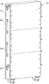
FIG. 1 is a perspective view of a battery receptacle in one embodiment of the container energy storage system of the present invention;
FIG. 2 is a perspective view from the other side of the perspective of FIG. 1;
fig. 3 is a perspective view of the battery box with left and right side seal plates removed;
FIG. 4 is a schematic view of a frame structure of a battery box;
FIG. 5 is an orthographic view of the battery receptacle with the uppermost closure plate removed;
FIG. 6 is an enlarged view of a portion of FIG. 5 at A;
fig. 7 is an isolated schematic view of the battery module of fig. 5;
FIG. 8 is a top view of FIG. 5;
fig. 9 is a partial enlarged view at B in fig. 8;
FIG. 10 is a perspective view of a box connector on a battery box;
FIG. 11 is a perspective view of an adapter connector on a container body;
FIG. 12 is a perspective view of the receptacle connector mated with the adapter connector;
FIG. 13 is a cross-sectional view C-C of FIG. 12;
names of components corresponding to corresponding reference numerals in the drawings are: 10-a battery holder; 11-layer plate; 12-a front side sealing plate; 13-rear side sealing plate; 21-right side closing plate; 22-left side closing plate; 30-a battery management unit; 31-a fuse; 40-traveling wheels; 50-a box connector; 51-a housing; 52-wiring copper bar; 53-a plug spring; 60-module connecting rows; 70-a mating connector; 71-an adapter housing; 72-static side copper bar; 80-battery module, 81-module fixing plate; 82-pole; 90-battery module, 83-acquisition cable 83.
Detailed Description
In order to make the objects, technical solutions and advantages of the present invention more apparent, the present invention is described in further detail below with reference to the accompanying drawings and embodiments. It should be understood that the detailed description and specific examples, while indicating the preferred embodiment of the invention, are intended for purposes of illustration only and are not intended to limit the scope of the invention. The components of embodiments of the present invention generally described and illustrated in the figures herein may be arranged and designed in a wide variety of different configurations.
Thus, the following detailed description of the embodiments of the present invention, presented in the figures, is not intended to limit the scope of the invention, as claimed, but is merely representative of selected embodiments of the invention. All other embodiments, which can be derived by a person skilled in the art from the embodiments of the present invention without making any creative effort, shall fall within the protection scope of the present invention.
It is noted that the relational terms such as "first" and "second," and the like, which may be present in the embodiments of the present invention, are used solely to distinguish one entity or action from another entity or action without necessarily requiring or implying any actual such relationship or order between such entities or actions. Also, the terms "comprises," "comprising," or any other variation thereof, are intended to cover a non-exclusive inclusion, such that a process, method, article, or apparatus that comprises a list of elements does not include only those elements but may include other elements not expressly listed or inherent to such process, method, article, or apparatus. Without further limitation, the possible appearances of the phrase "comprising one of the elements 8230 \8230;" defining elements does not exclude the presence of additional like elements in the process, method, article, or apparatus that comprises such elements.
In the description of the present invention, unless otherwise expressly specified or limited, the terms "mounted," "connected," and "connected" when they are used are to be construed broadly, e.g., as meaning a fixed connection, a removable connection, or an integral connection; can be mechanically or electrically connected; either directly or indirectly through intervening media, or may be interconnected between two elements. The specific meaning of the above terms in the present invention can be understood by those skilled in the art from specific situations.
In the description of the invention, unless otherwise explicitly specified or limited, the term "provided" should be understood broadly, for example, the object provided may be a part of the body, or may be arranged separately from the body and connected to the body, which may or may not be detachable. The specific meaning of the above terms in the present invention can be understood by those skilled in the art from specific situations.
The present invention will be described in further detail with reference to examples.
Embodiment 1 of the container energy storage system of the present invention:
the container energy storage system comprises a container (not shown in the figure) and a battery subrack, the whole structure of the container is the same as that of the container in the prior art, but the inner bottom surface of the container is provided with a subrack rail, and the subrack rail is, for example, made of channel steel and used for guiding the battery subrack to move in place and is spliced with an adapter connector 70 arranged in the container. The battery subrack is moved by the walking wheels 40 at the bottom, and the subrack rail is a groove-shaped rail and is provided with a guide groove for guiding the walking wheels 40.
The battery box has a structure as shown in fig. 1, 2, 3 and 4, and includes a battery rack 10, a traveling wheel 40 and a sealing plate, and a battery module 80 is installed inside the battery box when in use. The battery frame 10 is of a frame structure, as shown in fig. 4, seven layers of laminates 11 are fixed on the battery frame 10 through welding or bolt connection, the laminates 11 enable the battery frame 10 to be arranged in multiple layers in the vertical direction to form module mounting layers which are stacked up and down, and the battery modules 80 are installed in layers. The whole battery holder 10 is in a vertically placed cuboid structure, the width is 180 to 200mm, the depth is 800 to 1000mm, the height is 1700 to 1900mm, and the side face with the smallest area is positioned at the upper side and the lower side. The corresponding battery module 80 is 700 to 800mm long, 180 to 200mm wide and 180 to 250mm high. The traveling wheels 40 are arranged at the bottom of the battery rack 10, and are four in total, two in front and at the back, and the mode of combining universal wheels or the universal wheels and the directional wheels can be selected, so that the battery plug box can move, and the battery plug box and the adaptive connector 70 can be conveniently connected and the battery plug box can be conveniently transported in a turnover mode.
The shrouding sets up around battery frame 10, including front side shrouding 12, rear side shrouding 13, left side shrouding 22 and right side shrouding 21 for enclose into confined battery module accommodation space. The front-back direction is the depth direction of the battery box.
The left and right cover plates 22 and 21 are fixed to the battery holder 10 by screws. The left side shrouding 22 and the right side shrouding 21 are formed by the PCI heat conduction material, form the samming board for the heat of balanced battery module 80 makes the temperature of battery module 80 unanimous in the battery subrack. The left and right sides of naked electric core bonds in battery module 80 has heat conduction bed course, and the heat conduction bed course is heat conduction silica gel pad for the setting is between battery module 80 and left side shrouding 22 and between battery module 80 and right side shrouding 21, and pastes tight battery module 80 and corresponding shrouding simultaneously, can realize thermal conduction.
As shown in fig. 1, 3 and 5, a Battery Management Unit (BMU) 30 is disposed on the front side sealing plate 12, and the battery management unit 30 may adopt a structure in the prior art, and is configured to implement functions of voltage acquisition, temperature acquisition, current acquisition, insulation detection, active equalization, and the like. The battery management unit 30 can be fixed with the battery rack 10 directly or through a switching bracket, and in the embodiment, three battery management units 30 are adopted and are arranged in sequence from top to bottom. The rear side sealing plate 13 is provided with a plug box connector 50 which is positioned on one side of the battery plug box in the horizontal direction and is used for being plugged with an adaptive connector 70 in the container energy storage system when the battery plug box moves by virtue of the travelling wheels 40 so as to realize power supply. The subrack connector 50 comprises a positive electrode connector and a negative electrode connector, connector fixing holes are formed in the upper portion and the lower portion of the rear sealing plate respectively, the subrack connector 50 is fixed to the rear supporting plate and arranged at the top and the bottom of the battery subrack respectively, and extends out of the rear sealing plate to form positive and negative electrode output ends of the battery subrack so as to achieve power supply.
As shown in fig. 10, 12 and 13, the box connector 50 is a drawer type connector, and includes a housing 51, a wiring copper bar 52 and a plug spring 53. The housing 51 is adapted to be secured to a sealing plate of the battery holder 10, and is made of an insulating material to ensure the safety of the inserting and pulling operation. The wiring copper bar 52 is provided with a bolt through hole for electrically conducting with the pole 82 of the battery module 80 through the conductive bar; the inserting springs 53 are positioned in the shell 51 and are in conductive connection with the wiring copper bars 52, and the inserting springs 53 are arranged in two rows at intervals and have elasticity and are used for being clamped on the static side copper bars 72 on the adapter connector 70.
As shown in fig. 11, 12 and 13, the adapter connector 70 includes an adapter housing 71 and a stationary copper bar 72, the stationary copper bar 72 can be connected to other battery plug boxes or system connection portions through other adapter copper bars, the thickness of the stationary copper bar 72 is greater than the distance between the two rows of plug springs 53, and the plug-in is ensured to be tight after being plugged.
As shown in fig. 5, 6, 8 and 9, the battery box further includes a fuse 31, the top plate 11 of the battery rack 10 is provided with a fixing hole, and the fuse 31 can be fixed with the top plate 11 through a bracket or an insulator; the fuse 31 is connected in series with the top box connector 50 and then outputs the output to the outside, so that the short circuit in a single battery box can be prevented from affecting other battery boxes in the energy storage system.
As shown in fig. 3, the battery compartment further includes a module fixing plate 81, and the module fixing plate 81 is bridged between the end of the battery module 80 and the frame of the battery rack 10, and is fixed to the end of the battery module 80 and the frame of the battery rack 10 by screws, respectively, for fixing the battery module 80 to the battery rack 10. As a prior art, the battery module 80 is composed of a cell and a cell holder; as shown in fig. 7, the battery module 80 is provided with a collecting cable 83 for battery management, and the two ends of the battery module 80 are further respectively provided with positive and negative poles 82 for power output of the battery module 80.
When this battery subrack is packed into container energy storage system, directly rely on walking wheel 40 to remove to adaptation connector 70 is to inserting in can making subrack connector 50 on the battery subrack target in place with energy storage system, and is convenient and reliable, makes the convenient plug of battery subrack and maintenance, can realize the electrified plug of battery subrack, and required transfer operating space is little, is favorable to improving energy storage system's bulk density, and space utilization is high. The battery module 80 uses a large module with multiple electric cores connected in series and parallel, the modules are arranged layer by layer and connected through the module connecting bar 60, as shown in fig. 2, the use of power cables and connectors is reduced, the connection is more reliable, and the cost is lower. The rear side sealing plate 13 is provided with a connecting row through hole for the module connecting row 60 to pass through.
The above description is only a preferred embodiment of the present application, and not intended to limit the present application, the scope of the present application is defined by the appended claims, and all changes in equivalent structure made by using the contents of the specification and the drawings of the present application should be considered as being included in the scope of the present application.
Claims (8)
1. The container energy storage system comprises a container and a battery inserting box;
its characterized in that, the battery subrack includes:
the battery rack (10) is arranged in multiple layers in the vertical direction to form a module mounting layer which is stacked up and down, the battery modules (80) are arranged in layers, and each battery module (80) consists of a battery core and a battery core retainer;
the travelling wheels (40) are arranged at the bottom of the battery rack (10) and are used for moving the battery inserting box;
the sealing plates are arranged on the periphery of the battery rack (10) and used for enclosing a closed battery module accommodating space;
the plug-in box connector (50) is arranged on one side of the battery plug-in box in the horizontal direction and is used for being plugged with an adaptive connector (70) in the container energy storage system to realize power supply when the battery plug-in box moves by virtue of the travelling wheels (40);
the plug-in box connectors (50) comprise a positive connector and a negative connector, and the two plug-in box connectors (50) are respectively arranged at the top and the bottom of the battery plug-in box;
the box connector (50) is a drawer connector comprising:
a housing (51) for securing to a closure plate of the battery holder (10);
the wiring copper bar (52) is used for being connected with a pole (82) of the battery module (80);
the plug springs (53) are in conductive connection with the wiring copper bars (52), and two rows of the plug springs (53) are arranged at intervals and are used for being clamped on the static side copper bars (72) on the adaptive connector (70);
a plug-in box track is arranged in the container and used for guiding the travelling wheels (40) of the battery plug-in box to guide a plug-in box connector (50) on the battery plug-in box to be connected with an adaptive connector (70) in the container energy storage system.
2. The container energy storage system of claim 1, wherein the battery receptacle further comprises:
and a module connecting bar (60) for connecting the battery modules (80) in the corresponding two-layer module mounting layer.
3. The container energy storage system of claim 1, wherein the closure panels comprise a front side closure panel (12), a rear side closure panel (13), a left side closure panel (22) and a right side closure panel (21), the box connector (50) is provided on the rear side closure panel (13), and the battery management unit (30) is provided on the front side closure panel (12);
the battery plug-in box further comprises a heat conduction cushion layer, wherein the heat conduction cushion layer is used for being arranged between the battery module (80) and the left side sealing plate (22) and between the battery module (80) and the right side sealing plate (21), and clings to the battery module (80) and the corresponding sealing plates at the same time for realizing heat conduction.
4. The container energy storage system of claim 3, wherein the thermally conductive underlayment is bonded to the bare cells of the battery module (80).
5. The container energy storage system of claim 3, wherein the left and right closure plates (22, 21) are PCI thermally conductive material for equalizing the heat of the battery modules (80).
6. A container energy storage system according to claim 3 wherein the left and right closure panels (22, 21) are releasably securable to the battery rack (10).
7. A container energy storage system according to claim 1, characterised in that a fuse (31) is secured within the battery rack (10), the fuse (31) being connected in series to a corresponding box connector (50).
8. A container energy storage system according to claim 1, wherein the battery box further comprises a module securing plate (81), the module securing plate (81) spanning between an end of the battery module (80) and the frame of the battery stand (10) for securing the battery module (80) to the battery stand (10).
Priority Applications (1)
| Application Number | Priority Date | Filing Date | Title |
|---|---|---|---|
| CN202011279711.9A CN112768820B (en) | 2020-11-16 | 2020-11-16 | Container energy storage system |
Applications Claiming Priority (1)
| Application Number | Priority Date | Filing Date | Title |
|---|---|---|---|
| CN202011279711.9A CN112768820B (en) | 2020-11-16 | 2020-11-16 | Container energy storage system |
Publications (2)
| Publication Number | Publication Date |
|---|---|
| CN112768820A CN112768820A (en) | 2021-05-07 |
| CN112768820B true CN112768820B (en) | 2022-10-18 |
Family
ID=75693181
Family Applications (1)
| Application Number | Title | Priority Date | Filing Date |
|---|---|---|---|
| CN202011279711.9A Active CN112768820B (en) | 2020-11-16 | 2020-11-16 | Container energy storage system |
Country Status (1)
| Country | Link |
|---|---|
| CN (1) | CN112768820B (en) |
Families Citing this family (6)
| Publication number | Priority date | Publication date | Assignee | Title |
|---|---|---|---|---|
| CN215644823U (en) * | 2021-07-28 | 2022-01-25 | 天合光能股份有限公司 | Energy storage unit and energy storage battery using same |
| CN113991262B (en) * | 2021-09-06 | 2023-04-14 | 福建船政交通职业学院 | Energy storage battery overheat protection system |
| CN114142277A (en) * | 2021-11-30 | 2022-03-04 | 水发兴业能源(珠海)有限公司 | Quick plug electrical connector, electrical integration function battery frame and energy storage container |
| CN114744348B (en) * | 2022-05-17 | 2023-11-14 | 江苏富士特电气技术有限公司 | Electrochemical energy storage device adapting to multiple types of electric appliances |
| CN115312935A (en) * | 2022-08-24 | 2022-11-08 | 中国华能集团清洁能源技术研究院有限公司 | Multi-type battery collaborative energy storage battery plug box and battery cluster |
| CN116435838A (en) * | 2023-06-12 | 2023-07-14 | 苏州精控能源科技有限公司 | Battery pack electric connection structure |
Citations (10)
| Publication number | Priority date | Publication date | Assignee | Title |
|---|---|---|---|---|
| CN202399877U (en) * | 2011-12-31 | 2012-08-29 | 河南速达电动汽车科技有限公司 | Back-arranged energy storing device of electric automobile |
| KR20140061561A (en) * | 2012-11-12 | 2014-05-22 | 주식회사 엘지화학 | Energy storage system of improved assembly characteristic and space utilization |
| CN206685713U (en) * | 2017-04-11 | 2017-11-28 | 深圳市科陆电子科技股份有限公司 | A kind of energy storage container |
| WO2019100926A1 (en) * | 2017-11-23 | 2019-05-31 | 中车株洲电力机车有限公司 | Energy storage power supply and rail vehicle |
| CN110190652A (en) * | 2019-06-20 | 2019-08-30 | 范家林 | A kind of intelligent heat dissipation mobile container integrated energy storage system |
| CN209497275U (en) * | 2019-04-24 | 2019-10-15 | 深圳市聚能优电科技有限公司 | It is a kind of applied in temporary power bavin storage system can increase-volume energy storage device in parallel |
| CN210074541U (en) * | 2019-08-19 | 2020-02-14 | 常州冠昌电器设备有限公司 | Modularized integrated energy storage box body for transformer substation |
| CN210182462U (en) * | 2019-09-25 | 2020-03-24 | 上海豫源电力科技有限公司 | Battery rack module capable of quickly replacing energy storage PACK |
| CN211480140U (en) * | 2020-02-24 | 2020-09-11 | 阳光电源股份有限公司 | Container energy storage device and energy storage system |
| CN111864138A (en) * | 2020-07-20 | 2020-10-30 | 日照鑫泰莱光电有限公司 | Lithium iron phosphate energy storage battery cabinet for solar energy saving system |
Family Cites Families (10)
| Publication number | Priority date | Publication date | Assignee | Title |
|---|---|---|---|---|
| CN205376590U (en) * | 2015-11-27 | 2016-07-06 | 山东精工电子科技有限公司 | Drawer type lithium ion battery cabinet |
| CN207398917U (en) * | 2017-06-12 | 2018-05-22 | 中航锂电(洛阳)有限公司 | A kind of energy storage cabinet and the energy-storage system using the energy storage cabinet |
| CN207852769U (en) * | 2018-02-28 | 2018-09-11 | 宿迁杉杉运通新能源系统有限公司 | A kind of battery energy storage device |
| CN208509425U (en) * | 2018-06-27 | 2019-02-15 | 中航锂电(洛阳)有限公司 | Battery subrack cabinet |
| CN208478437U (en) * | 2018-07-31 | 2019-02-05 | 江苏乐希科技有限公司 | A kind of energy storage cabinet with rapid plug structure |
| KR102360951B1 (en) * | 2019-01-17 | 2022-02-08 | 주식회사 엘지에너지솔루션 | Battery rack and energy storage system comprising the battery rack |
| CN209357760U (en) * | 2019-01-28 | 2019-09-06 | 深圳市嘉名科技有限公司 | A kind of lithium battery and lithium battery encapsulation shell |
| CN110366358B (en) * | 2019-07-22 | 2024-03-29 | 浙江嘉熙科技股份有限公司 | Thermal superconducting plate and thermal superconducting radiator |
| CN210778889U (en) * | 2019-09-17 | 2020-06-16 | 无锡旭浦能源科技有限公司 | Energy storage management system of high-power battery pack |
| CN211320187U (en) * | 2020-03-18 | 2020-08-21 | 江苏大秦新能源科技有限公司 | Stacked battery energy storage system |
-
2020
- 2020-11-16 CN CN202011279711.9A patent/CN112768820B/en active Active
Patent Citations (10)
| Publication number | Priority date | Publication date | Assignee | Title |
|---|---|---|---|---|
| CN202399877U (en) * | 2011-12-31 | 2012-08-29 | 河南速达电动汽车科技有限公司 | Back-arranged energy storing device of electric automobile |
| KR20140061561A (en) * | 2012-11-12 | 2014-05-22 | 주식회사 엘지화학 | Energy storage system of improved assembly characteristic and space utilization |
| CN206685713U (en) * | 2017-04-11 | 2017-11-28 | 深圳市科陆电子科技股份有限公司 | A kind of energy storage container |
| WO2019100926A1 (en) * | 2017-11-23 | 2019-05-31 | 中车株洲电力机车有限公司 | Energy storage power supply and rail vehicle |
| CN209497275U (en) * | 2019-04-24 | 2019-10-15 | 深圳市聚能优电科技有限公司 | It is a kind of applied in temporary power bavin storage system can increase-volume energy storage device in parallel |
| CN110190652A (en) * | 2019-06-20 | 2019-08-30 | 范家林 | A kind of intelligent heat dissipation mobile container integrated energy storage system |
| CN210074541U (en) * | 2019-08-19 | 2020-02-14 | 常州冠昌电器设备有限公司 | Modularized integrated energy storage box body for transformer substation |
| CN210182462U (en) * | 2019-09-25 | 2020-03-24 | 上海豫源电力科技有限公司 | Battery rack module capable of quickly replacing energy storage PACK |
| CN211480140U (en) * | 2020-02-24 | 2020-09-11 | 阳光电源股份有限公司 | Container energy storage device and energy storage system |
| CN111864138A (en) * | 2020-07-20 | 2020-10-30 | 日照鑫泰莱光电有限公司 | Lithium iron phosphate energy storage battery cabinet for solar energy saving system |
Also Published As
| Publication number | Publication date |
|---|---|
| CN112768820A (en) | 2021-05-07 |
Similar Documents
| Publication | Publication Date | Title |
|---|---|---|
| CN112768820B (en) | Container energy storage system | |
| US8652678B2 (en) | Battery pack system | |
| CA2841605A1 (en) | Battery pack system | |
| US20140220391A1 (en) | Power source apparatus, and vehicle and power storage device equipped with that power source apparatus | |
| WO2018169216A1 (en) | Battery module, battery pack comprising battery module, and vehicle comprising battery pack | |
| KR20120016351A (en) | Voltage sensing assembly and battery module employed with the same | |
| US20210296738A1 (en) | Battery Module and Battery Pack Including the Same | |
| JP2020077559A (en) | Battery module and battery pack | |
| CN113871771A (en) | Module of battery pack and battery pack | |
| CN113193294A (en) | Battery module and battery pack | |
| CN214176130U (en) | Battery inserting box for container energy storage system | |
| US20210273267A1 (en) | Battery Module and Battery Pack Including the Same | |
| EP3772124A1 (en) | Battery module and battery pack comprising same | |
| KR20210041284A (en) | Battery module and battery pack including the same | |
| CN114400414B (en) | Battery cell module and battery pack | |
| CN218300108U (en) | Battery subrack and energy storage container | |
| CN107994195A (en) | Battery core pin configuration for battery modules | |
| JP2022517687A (en) | Battery module and battery pack containing it | |
| CN216529149U (en) | Battery module and battery pack | |
| KR20210041285A (en) | Battery module and battery pack including the same | |
| CN219203326U (en) | Energy storage device | |
| CN220021453U (en) | Battery and vehicle body integrated structure and vehicle | |
| KR102240921B1 (en) | Battery pack | |
| KR20210042583A (en) | Battery module and battery pack including the same | |
| CN213959051U (en) | Module positioning mechanism of light truck battery pack |
Legal Events
| Date | Code | Title | Description |
|---|---|---|---|
| PB01 | Publication | ||
| PB01 | Publication | ||
| SE01 | Entry into force of request for substantive examination | ||
| SE01 | Entry into force of request for substantive examination | ||
| GR01 | Patent grant | ||
| GR01 | Patent grant |